Exhaust Manifold Installation - Right Side W/O RPO NC1 or NF7
- If the engine is equipped with coolant heaters, install the right side (1) heater as follows:
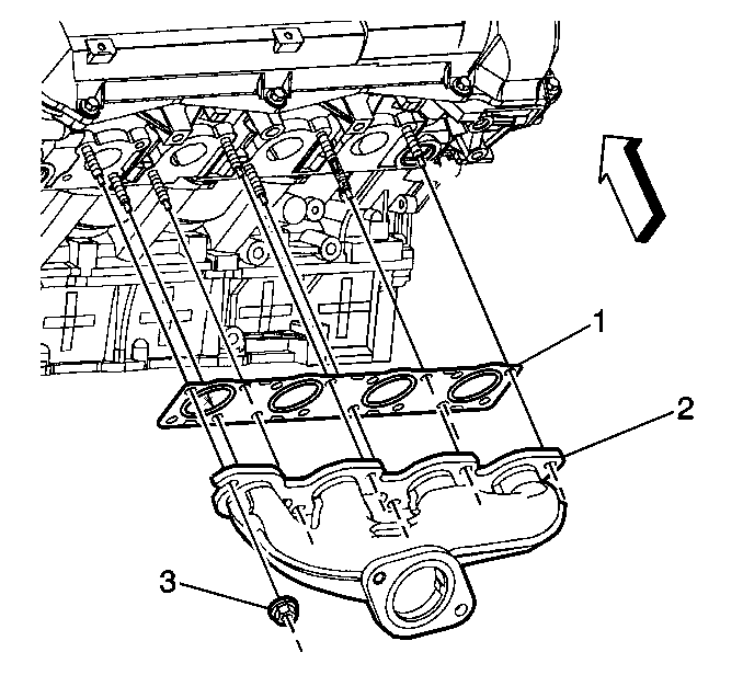
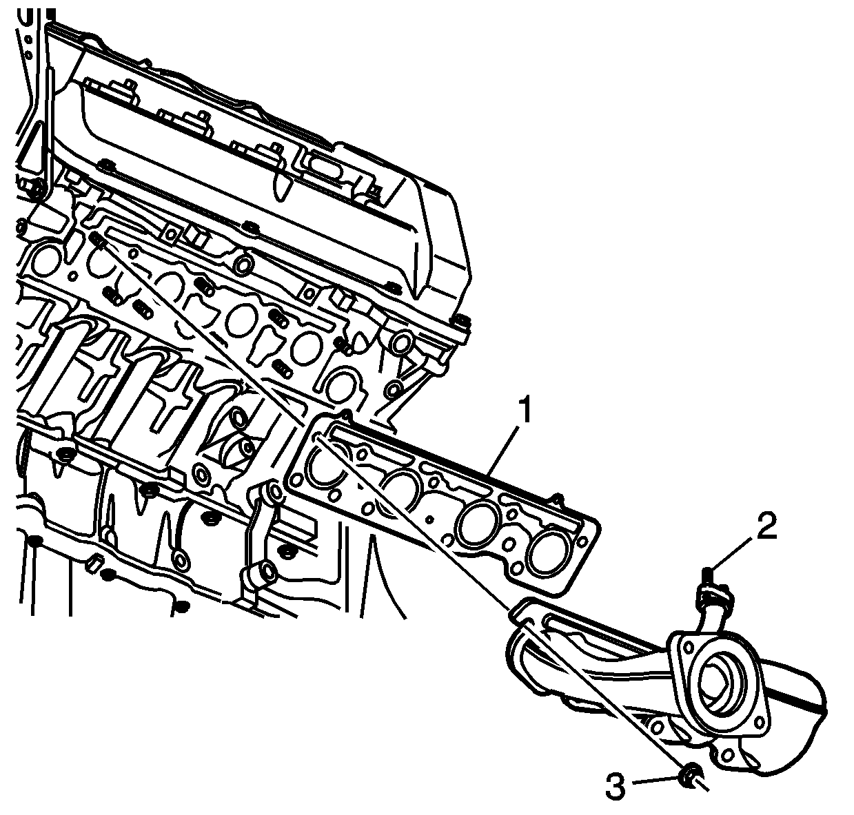
- Position a new manifold gasket (1) in place on the cylinder head studs.
- Using two hands, position the manifold (2) onto the cylinder head.
- Install two outer manifold nuts (3) to hold the manifold in place.
- Install the remaining manifold nuts.
- Coat the oxygen sensor threads with high temperature anti-seize, GM P/N 12377953 or equivalent.
- Install the oxygen sensor (1).
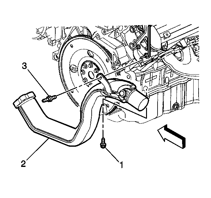
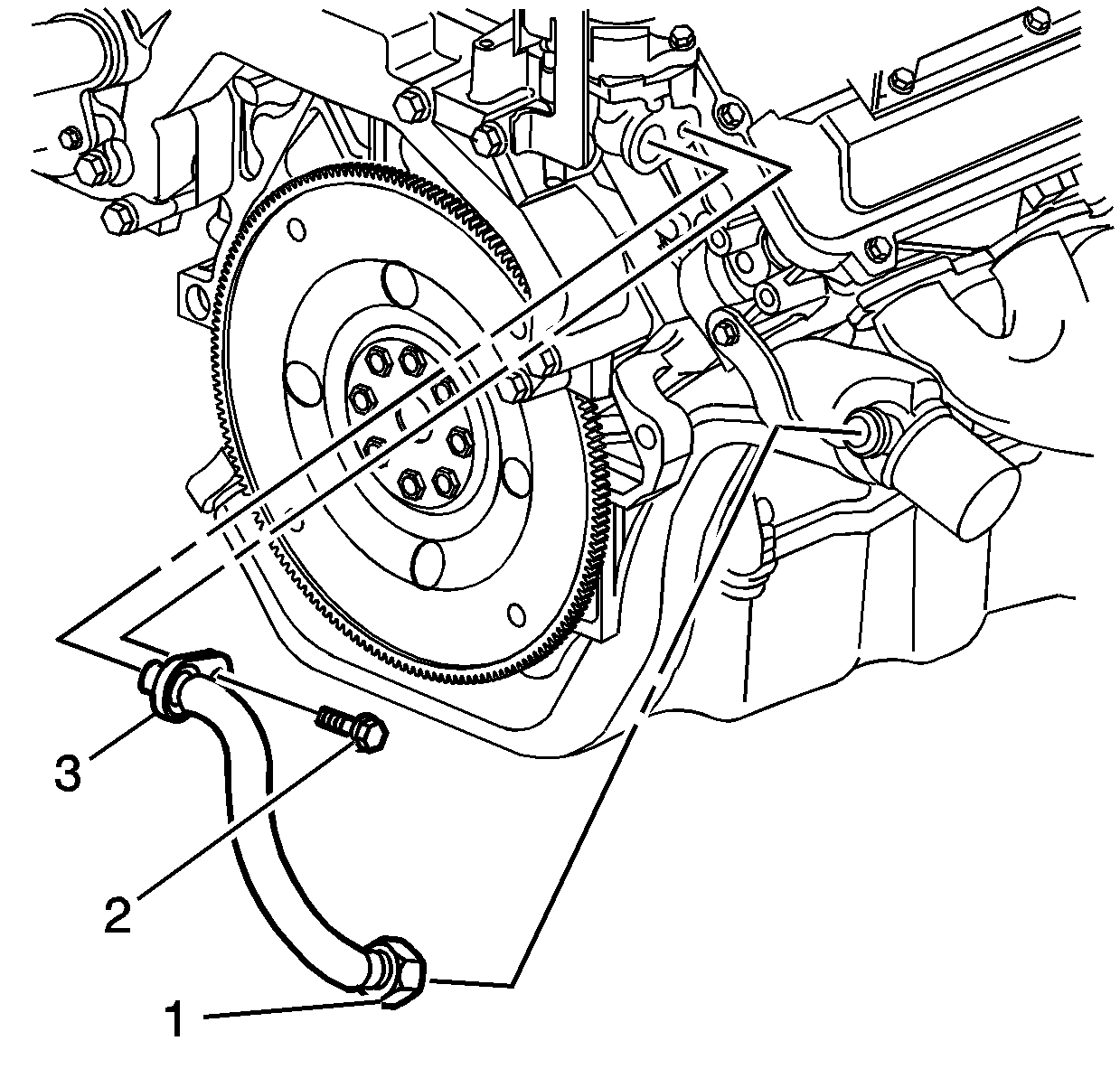
- Place the exhaust intermediate pipe (2) in position.
- Install the intermediate pipe stud at the cylinder head (3) and the bolt at the lower crankcase (1).
- Tighten the intermediate pipe-to-lower crankcase bolt (1) to 30 N·m (22 lb ft).
- Tighten the intermediate pipe-to-cylinder head stud (3) to 30 N·m (22 lb ft).
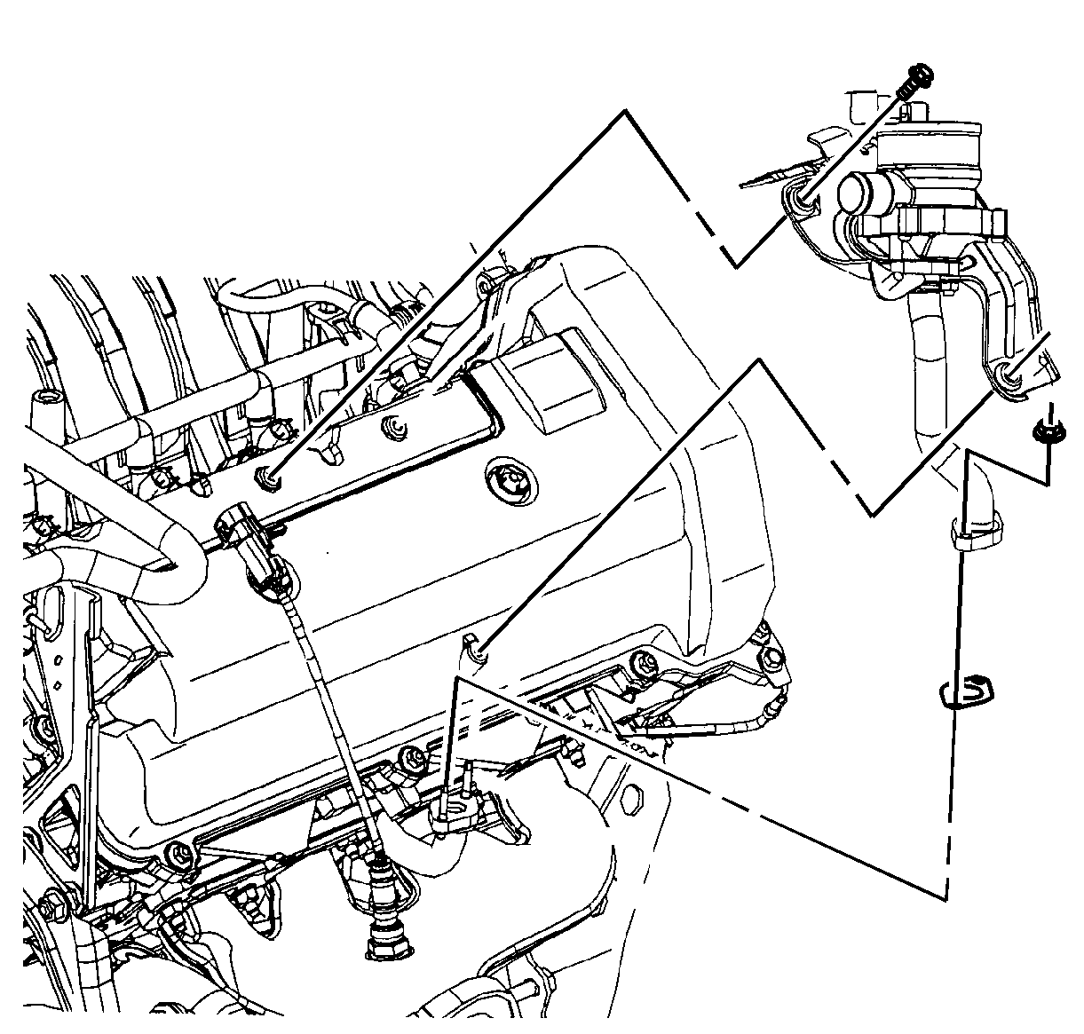
- Hand start the NEW EGR inlet tube to intermediate pipe nut (1) to prevent crossthreading.
- Connect the EGR inlet pipe flange (3) to the water crossover.
- Install the EGR inlet pipe to water crossover flange bolt (2).
Notice: Use the correct fastener in the correct location. Replacement fasteners must be the correct part number for that application. Fasteners requiring replacement or fasteners requiring the use of thread locking compound or sealant are identified in the service procedure. Do not use paints, lubricants, or corrosion inhibitors on fasteners or fastener joint surfaces unless specified. These coatings affect fastener torque and joint clamping force and may damage the fastener. Use the correct tightening sequence and specifications when installing fasteners in order to avoid damage to parts and systems.
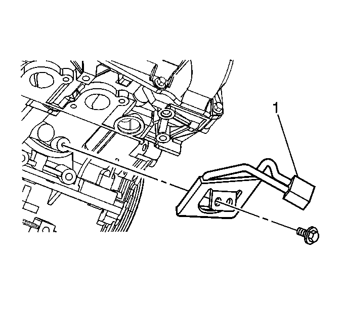
| 1.1. | Place the coolant heater (1) in position on the cylinder block. |
| 1.2. | Install the coolant heater bolt. |
Tighten
Tighten the coolant heater bolt to 10 N·m
(89 lb in).
Tighten
Tighten the exhaust manifold nuts (3) to
25 N·m (18 lb ft).
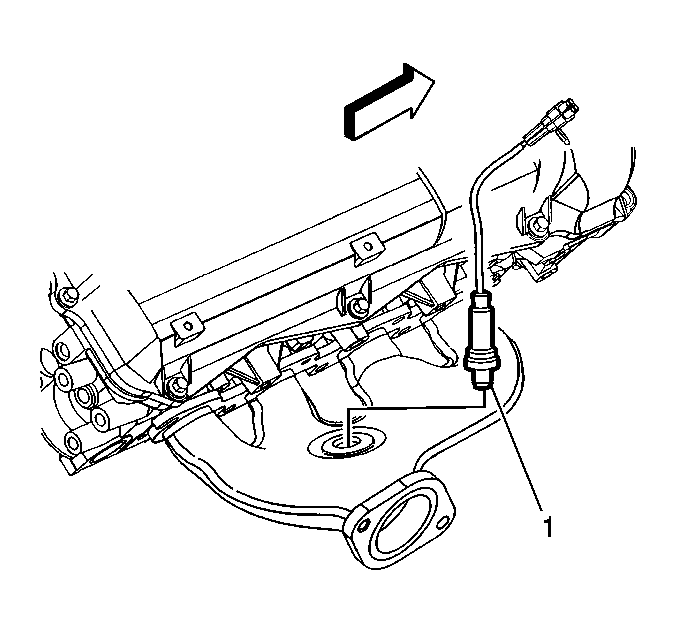
Tighten
Tighten the oxygen sensor to 40 N·m
(30 lb ft).
Tighten
Important: The exhaust gas recirculation (EGR) valve inlet pipe incorporates a crush seal connection at the water crossover. The EGR valve inlet pipe must be replaced if disconnected from the water crossover.
Tighten
Tighten the EGR inlet tube-to-intermediate pipe
nut to 60 N·m (44 lb ft).
Tighten
Tighten the EGR inlet tube to water crossover bolt
to 25 N·m (18 lb ft).
Exhaust Manifold Installation - Right Side With RPO NC1 or NF7
- If the engine is equipped with coolant heaters, install the right side (1) heater as follows:
- Position a new manifold gasket (1) in place on the cylinder head studs.
- Using two hands, position the manifold (2) onto the cylinder head.
- Install two outer manifold nuts (3) to hold the manifold in place.
- Install the remaining manifold nuts.
- Coat the oxygen sensor threads with high temperature anti-seize, GM P/N 12377953 or equivalent.
- Install the oxygen sensor (1).
- Install the NEW AIR valve pipe gasket.
- Install the AIR valve.
- Install the AIR valve bolts through the mounting bracket.
- Install the AIR valve pipe nuts to the exhaust manifold.
- Place the exhaust intermediate pipe (2) in position.
- Install the intermediate pipe stud at the cylinder head (3) and the bolt at the lower crankcase (1).
- Tighten the intermediate pipe-to-lower crankcase bolt (1) to 30 N·m (22 lb ft).
- Tighten the intermediate pipe-to-cylinder head stud (3) to 30 N·m (22 lb ft).
- Hand start the NEW EGR inlet tube to intermediate pipe nut (1) to prevent crossthreading.
- Connect the EGR inlet pipe flange (3) to the water crossover.
- Install the EGR inlet pipe to water crossover flange bolt (2).
Notice: Refer to Fastener Notice in the Preface section.
| 1.1. | Place the coolant heater (1) in position on the cylinder block. |
| 1.2. | Install the coolant heater bolt. |
Tighten
Tighten the coolant heater bolt to 10 N·m
(89 lb in).
Tighten
Tighten the exhaust manifold nuts (3) to
25 N·m (18 lb ft).
Tighten
Tighten the oxygen sensor to 40 N·m
(30 lb ft).
Important: DO NOT reuse the old secondary air injection (AIR) valve pipe gasket.
Tighten
Tighten the AIR valve bolts to 9 N·m
(80 lb in).
Tighten
Tighten the AIR valve pipe nuts to 9 N·m
(80 lb in).
Tighten
Important: The exhaust gas recirculation (EGR) valve inlet pipe incorporates a crush seal connection at the water crossover. The EGR valve inlet pipe must be replaced if disconnected from the water crossover.
Tighten
Tighten the EGR inlet tube-to-intermediate pipe
nut to 60 N·m (44 lb ft).
Tighten
Tighten the EGR inlet tube to water crossover bolt
to 25 N·m (18 lb ft).
