Removal Procedure
Caution: To avoid serious personal injury, do not stand over tire when inflating. The bead may break when the bead snaps over the safety hump. Do not exceed 275 kPa (40 psi) pressure when inflating any tire if beads are not seated. If 275 kPa (40 psi) pressure will not seat the beads, deflate, relubricate the beads and reinflate. Overinflation may cause the bead to break and cause serious personal injury.
Notice: Do not scratch or damage the clear coating on aluminum wheels with the tire changing equipment. Scratching the clear coating could cause the aluminum wheel to corrode and the clear coating to peel from the wheel.
Notice: Damage to either the tire bead or the wheel mounting holes can result from the use of improper wheel attachment or tire mounting procedures. It takes up to 70 seconds for all of the air to completely exhaust from a large tire. Failure to follow the proper procedures could cause the tire changer to put enough force on the tire to bend the wheel at the mounting surface. Such damage may result in vibration and/or shimmy, and under severe usage lead to wheel cracking.
Notice: When mounting the tires, use an approved tire mounting lubricant. DO NOT use silicon or corrosive base compounds to lubricate the tire bead and the wheel rim. A silicon base compound can cause the tire to slip on the rim. A corrosive type compound can cause tire or rim deterioration.
- Carefully remove the valve core and deflate the tire completely.
- Carefully lay the tire face down on a clean rubber or clean soft surface.
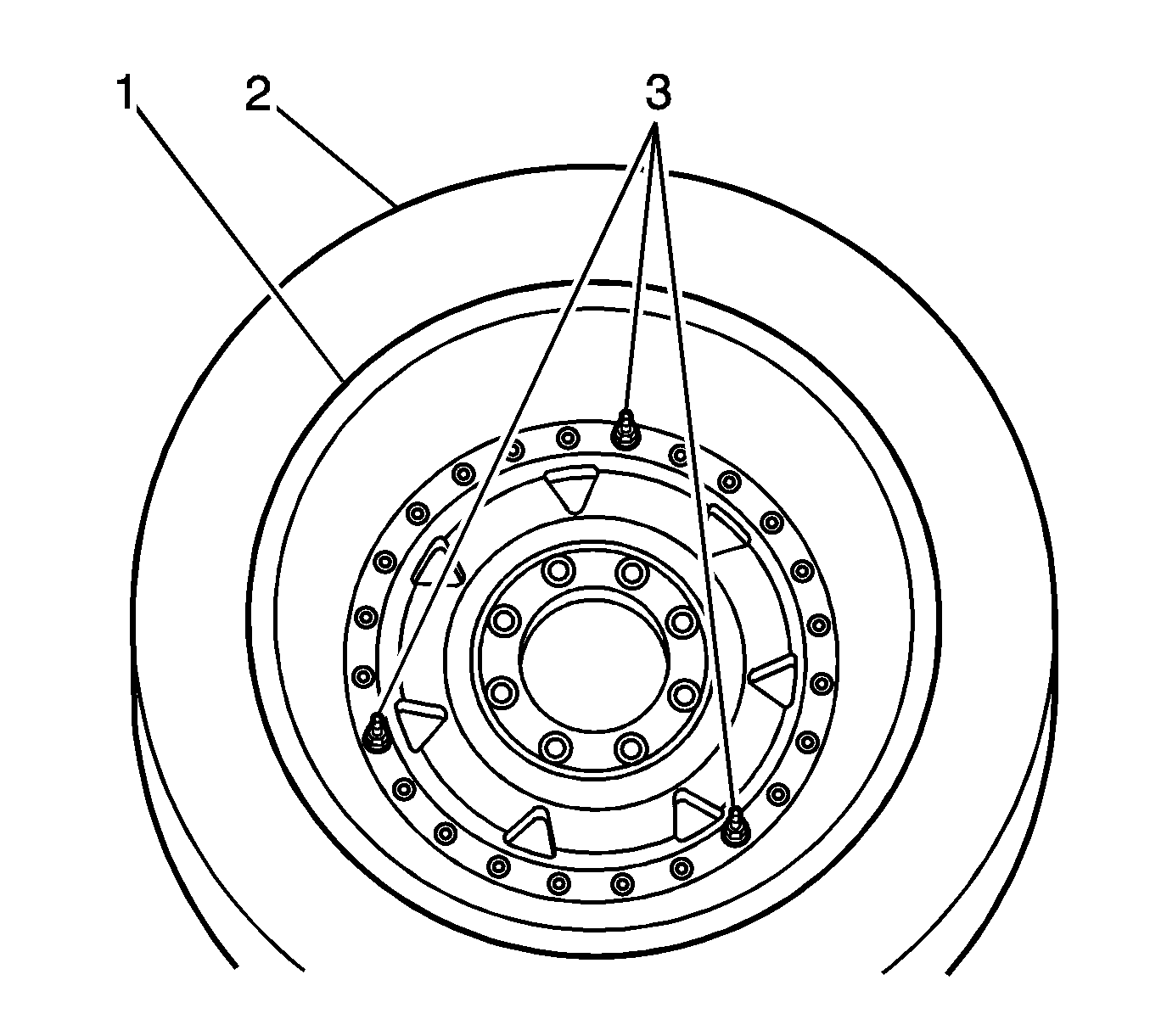
- Carefully loosen all wheel-clamping bolts 4 to 6 turns to release any trapped air pressure.
- Remove every other wheel-clamping bolt.
- Remove the remaining wheel-clamping bolts.
- Carefully turn the tire and wheel assembly over so the outer face of the wheel is facing up.
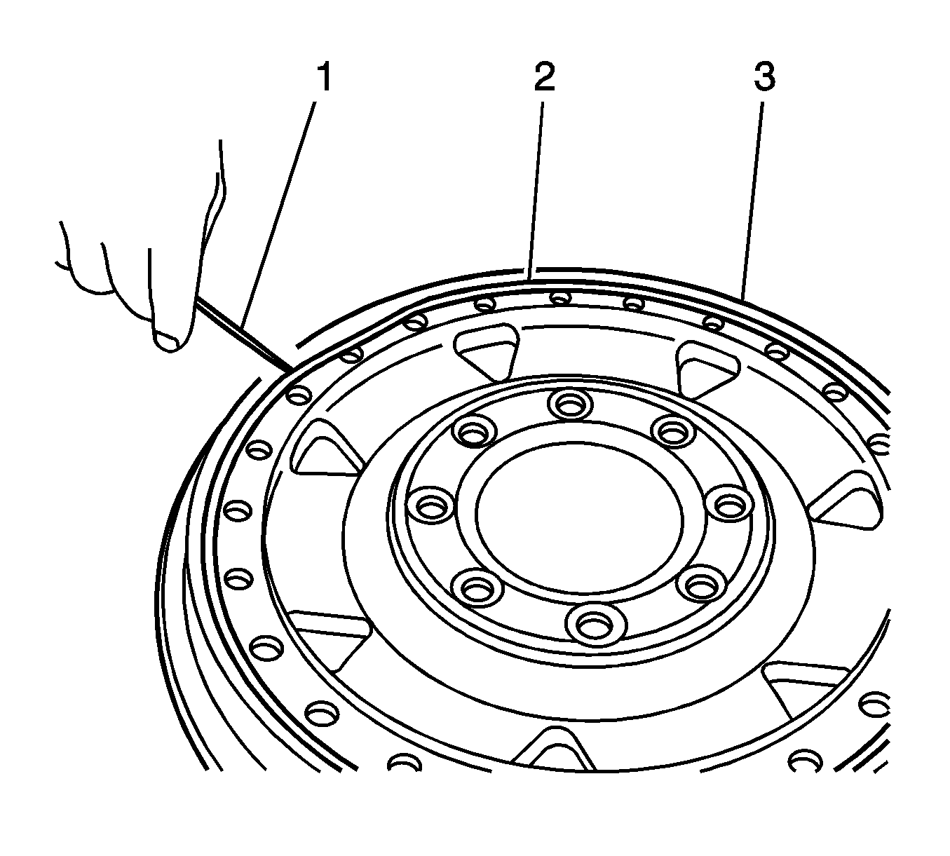
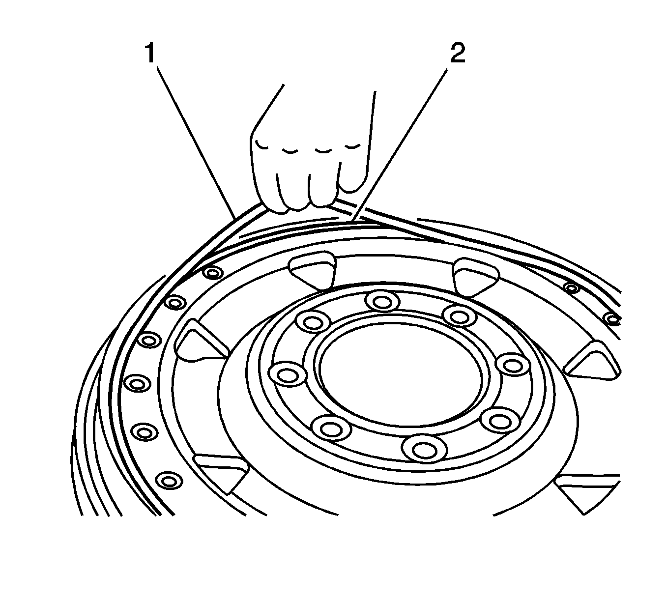
- Carefully insert the tire tool (2) between the tire bead and the wheel.
- Carefully insert a second tire tool (3) between the tire bead and wheel approximately five to six inches to the left of the first tire tool.
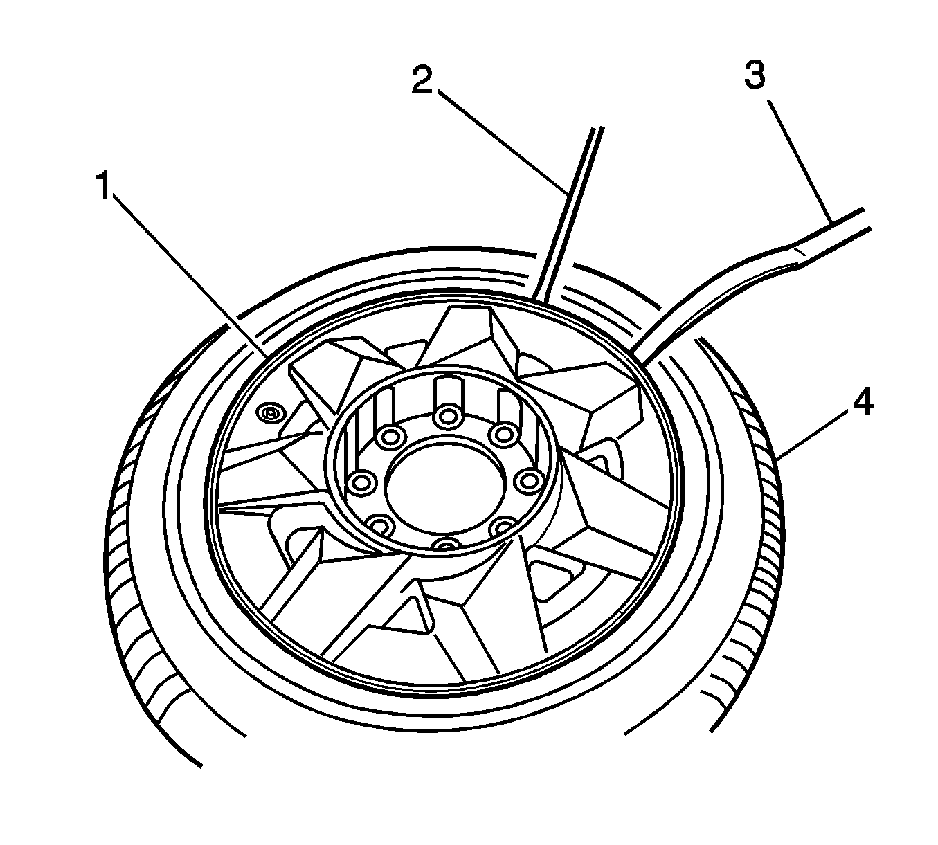
- Lift one tire tool upward applying pressure downward on the tire bead to release it from the wheel (1).
- Push downward on the second tire tool to lift the wheel and release the wheel (1) from the tire (4).
- Move the tire tools to the left 5 to 6 inches and repeat steps 7 through 10 until the wheel (1) can be removed from the tire.
- Remove the wheel outer face from the tire assembly.
- Carefully turn the tire over.
- Repeat steps 7 through 11 for the inner wheel half.
- Remove the inner wheel half from the tire assembly.
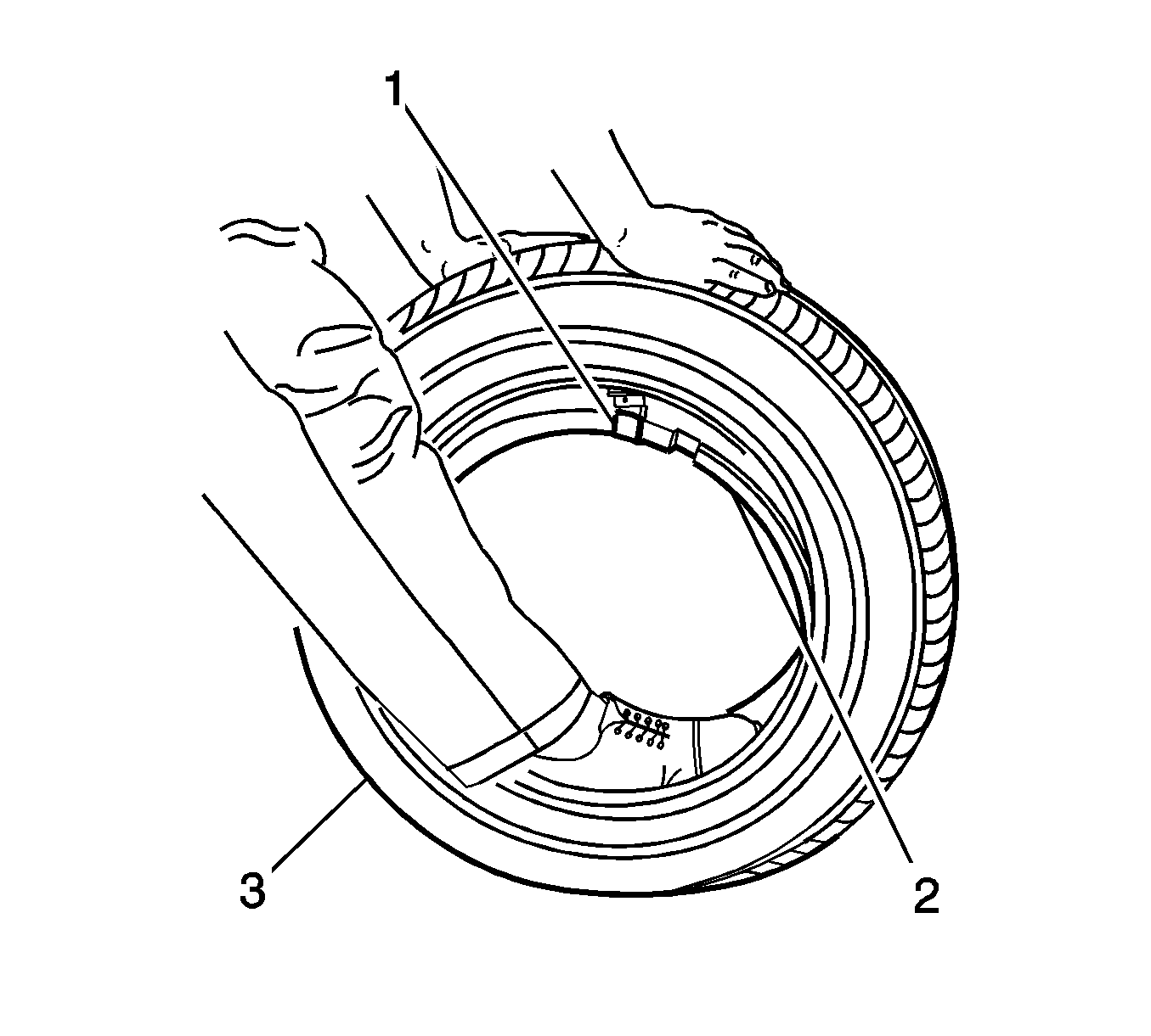
- Stand the wheel upright, so the tire pressure sensor assembly (1) is positioned to the top of the tire.
- Using your foot, push the tire insert (2) down into the tire (3).
- Move the tire insert (2) to one side of the tire to access the tire pressure sensor assembly (1).
- Remove the tire pressure sensor assembly (1).
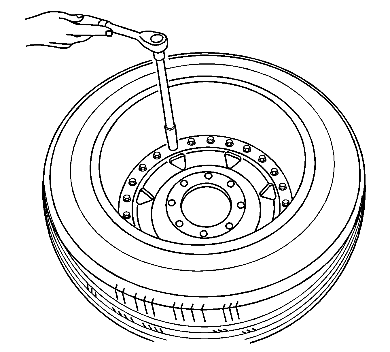
Important: DO NOT use an Air Impact Wrench.
Important: If replacing the outer wheel face remove and retain the valve stem.
Installation Procedure
- Using denatured alcohol, clean the tire beads.
- Inspect the insert and tire for the following:
- Replace the insert and tire if any of the above are found.
- Inspect the tire pressure sensor assembly for the following:
- Replace the tire pressure sensor assembly if any of the above are found.
- If replacing the tire pressure sensor assembly, remove the sensor Id sticker from the outer wheel mounting flange and clean the flange surface with denatured alcohol.
- Apply the new sensor Id sticker to the outer wheel mounting flange. The sensor Id sticker is required to be located on the outer wheel mounting flange for programing.
- Install the tire pressure sensor assembly (1) to the tire insert. Ensure that the tire pressure sensor assembly is aligned to the left edge of the air notch on the tire insert.
- Position the tire insert (1) so that it is centered in the tire (2).
- Using a flat-bladed tool (1) carefully remove and discard the wheel O-ring (2) from the outer wheel (3).
- Using denatured alcohol, clean the wheel sealing and mounting surfaces.
- Inspect the wheel for the following:
- Replace the wheel if any of the above are found.
- Apply lubricant GM P/N 12371287 (Canadian P/N 10953437) to the wheel O-ring.
- Install a new O-ring (1) to the outer wheel face groove (2).
- Apply a small amount of tire mounting lubricant GM P/N 12345884 (Canadian P/N 5728223) or equivalent to the tire beads.
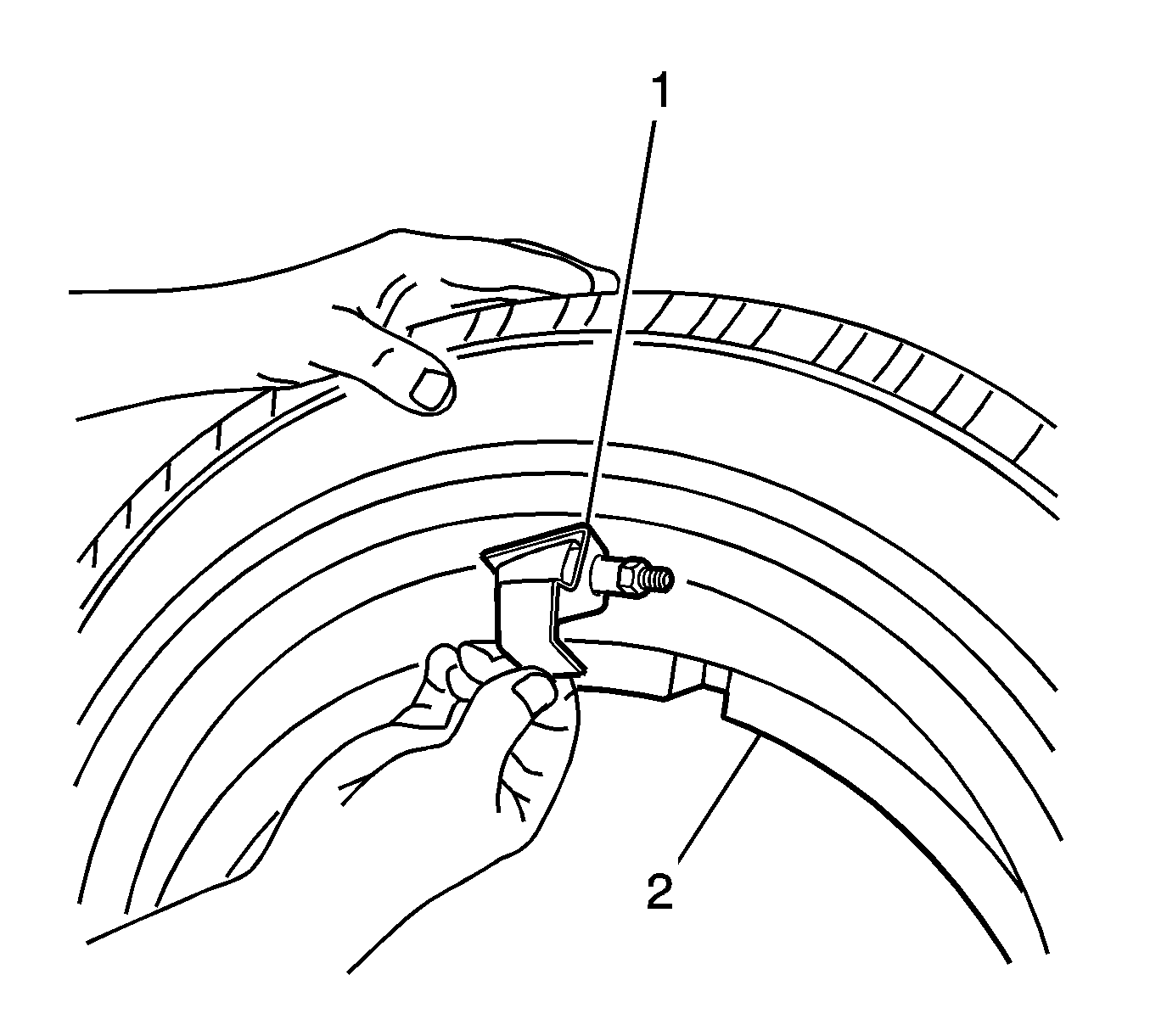
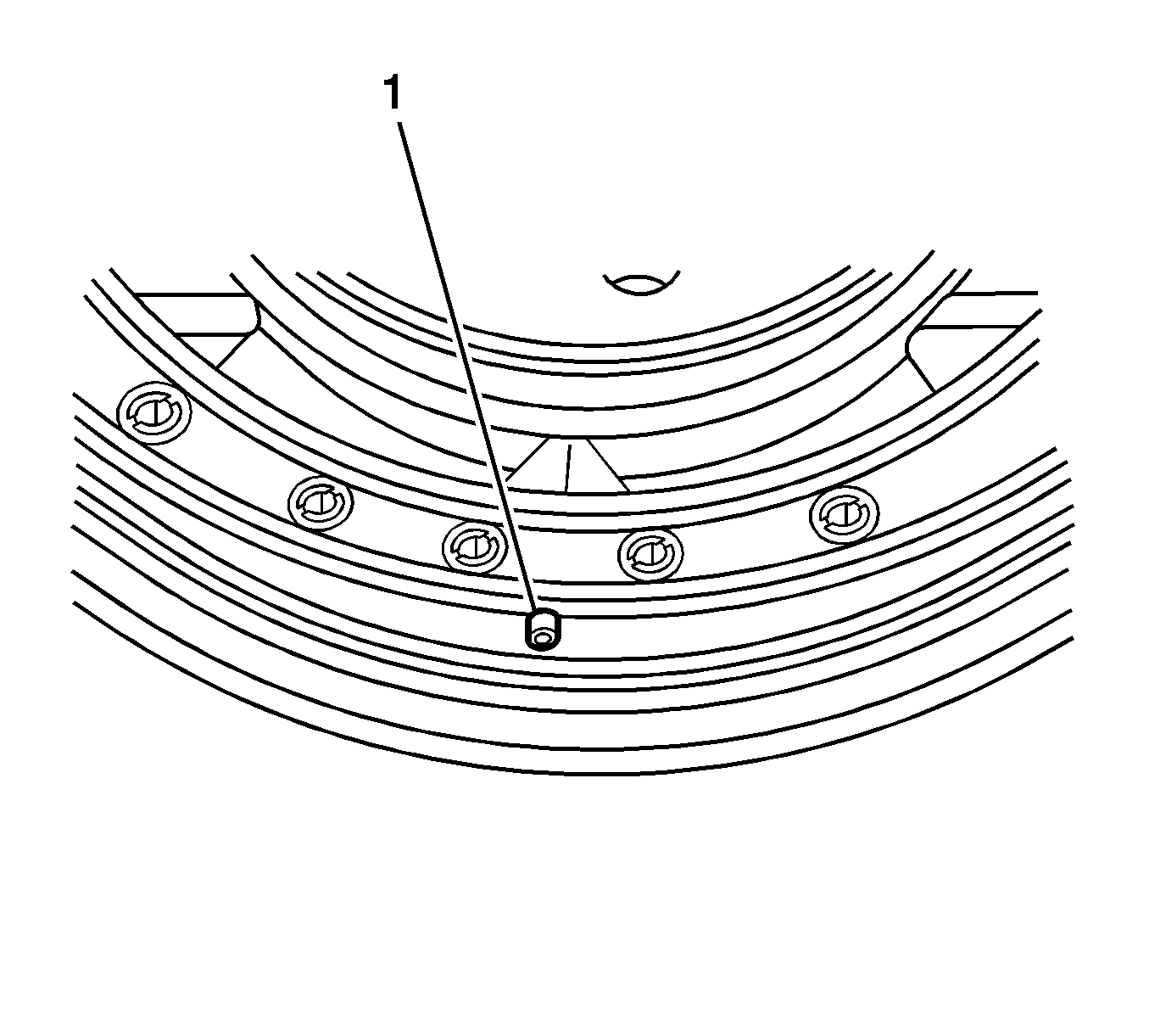
- Locate the air valve slot (1) on the back side of the outer wheel face.
- Locate the air notch (1) of the tire insert.
- Carefully place the outer wheel face on the tire/tire insert assembly, making sure to align the air valve notch with the tire insert air notch.
- Carefully push the outer wheel face onto the tire bead.
- Carefully turn the tire and outer wheel face over, facing down on a clean rubber or soft surface.
- Install the inner half of the wheel (1) into the tire (2).
- Install the guide studs (3) evenly spaced around the wheel .
- Thread the guide studs (3) into the outer wheel face.
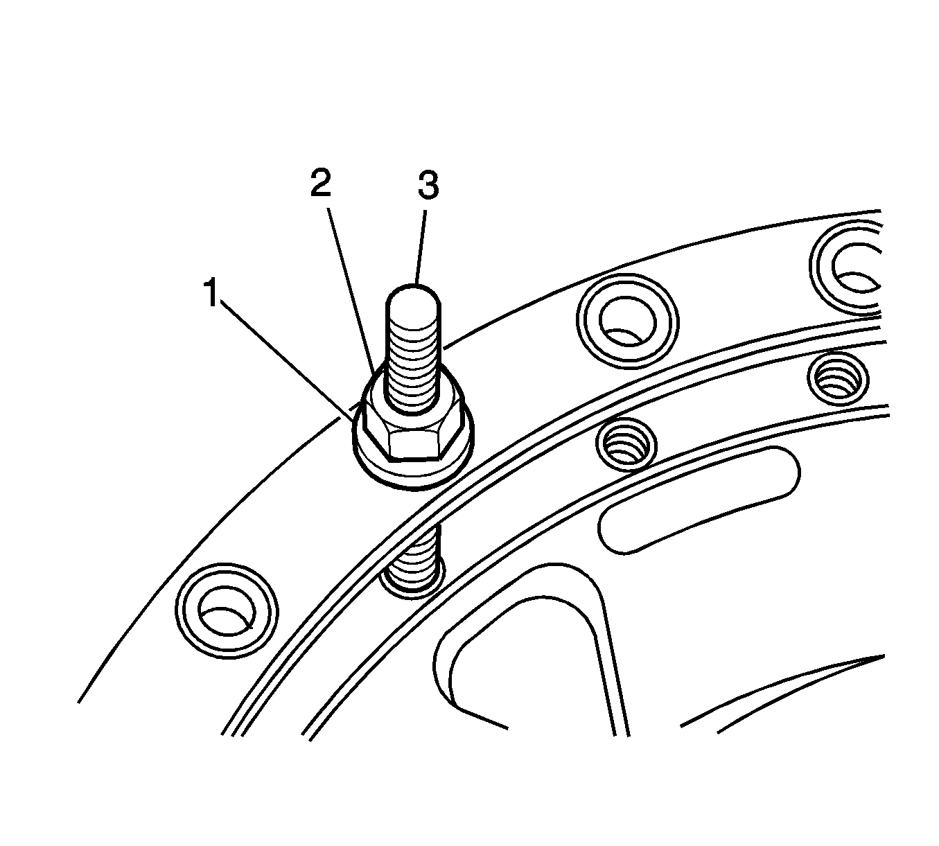
- Install the guide stud nuts (2) with washers (1).
- Tighten the guide stud mounting nuts (2) equally until the wheel halves are pulled together enough to install the new mounting bolts.
- Install the new wheel mounting bolts.
- Tighten the new wheel mounting bolts equally around the wheel.
- Remove the guide stud nuts (2) and washers (1).
- Remove the guide studs.
- Install the remaining mounting bolts.
- Inflate the tire assembly to 30 PSI to seat the tire on the wheel.
- Inflate the tire assembly to the proper air pressure.
- If the tire pressure sensor was replaced perform the tire pressure sensor learn procedure. Refer to Tire Pressure Sensor Learn .
| • | Cuts |
| • | Damaged tire bead |
| • | Shredding |
| • | Tears |
| • | Broken or damaged bracket |
| • | Broken or damaged tire pressure sensor |
| • | Bent rim flanges |
| • | Cracks |
Important: Failure to align the air notches will prevent tire from inflation.
Important: Ensure the O-ring is still seated in the outer wheel face groove and the air slot is aligned with the air notch on the insert.
Important: DO NOT use an Air Impact Wrench.
Notice: Refer to Fastener Notice in the Preface section.
Tighten
| • | Tighten the wheel mounting bolts equally in a circle pattern to 13.6 N·m (10 lb ft). |
| • | Tighten the wheel mounting bolts equally in a circle pattern again to 47.5 N·m (35 lb ft). |
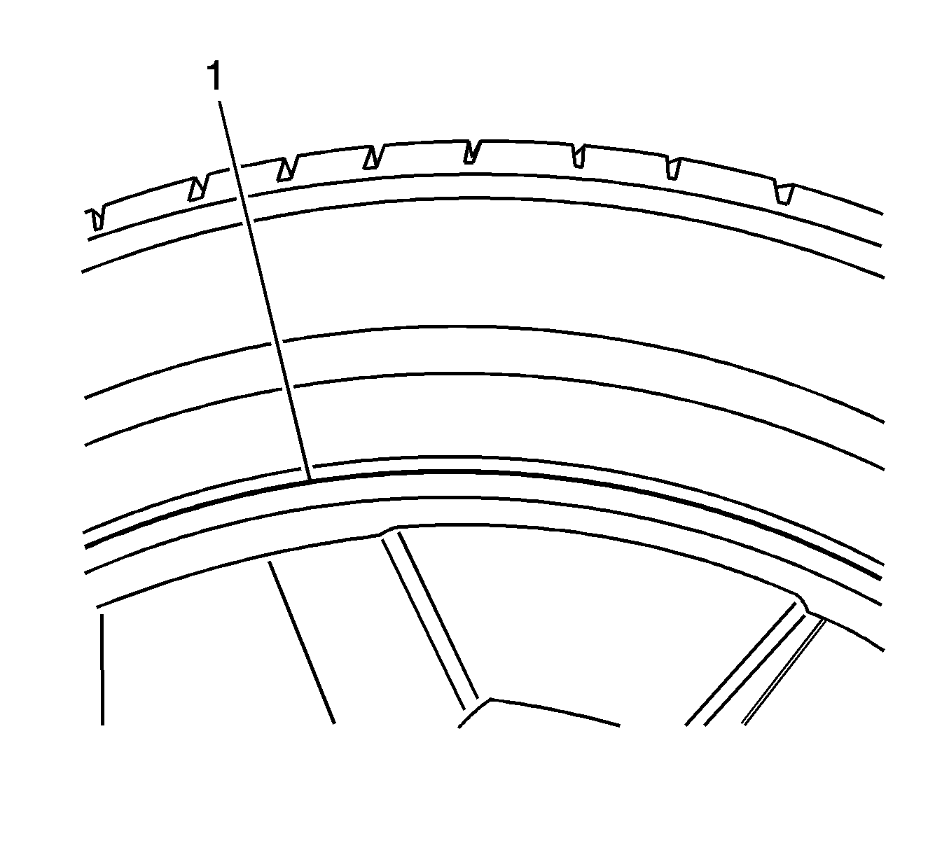
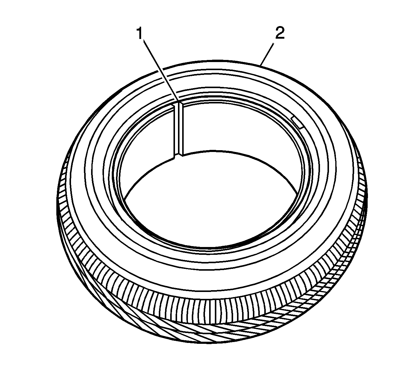
Important: Ensure the locating rings (1) are visible on both sides of the tire in order to verify the tire bead is fully seated on the wheel.
