Tools Required
| • | J 28467-B Universal Engine Support Fixture |
| • | J 42478 Engine Support Fixture Adapters |
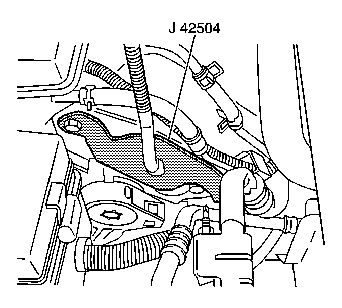
| • | J 42504 Engine Lift Bracket |
Installation Procedure
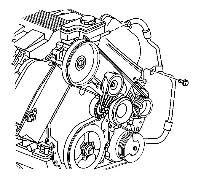
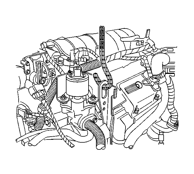
- Remove the bolt bracing the power steering return hose to the cylinder head.
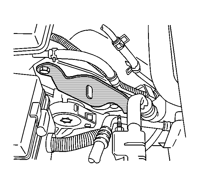
- Install the J 42504 to the cylinder head.
- Remove the air inlet grill. Refer to Air Inlet Grille Panel Replacement in Body Front End.
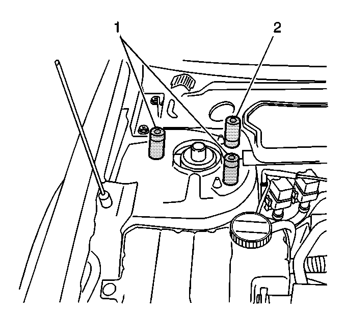
- Remove the rearward strut bolts from the right and left strut towers.
- Install the J 42478 (2) into the strut threads.
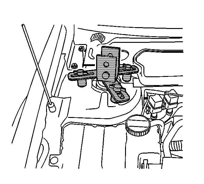
- Place the strut adapters (J 28467-33A) (1) on top of the four remaining forward strut tower bolts.
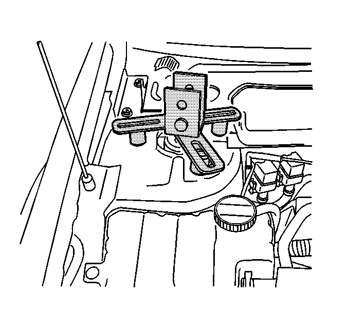
- Install the strut tower support assemblies (J 28467-5A) over the adapters J 42478 and (J 28467-33A).
- Install the T-Bolts to the J 42478 and (J 28467-33A).
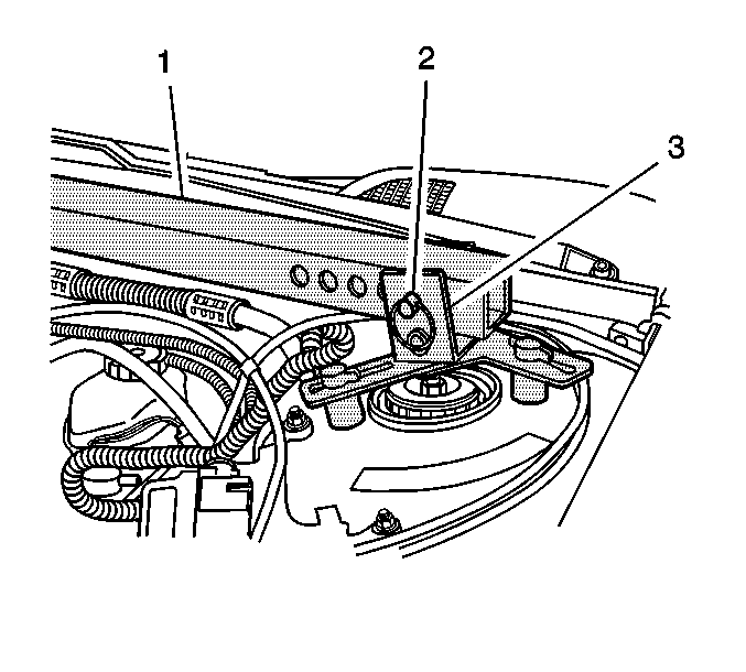
- Install the strut tower tube (J 28467-3) into the strut tower support assemblies (J 28467-5A).
- Install the 1/2 in. x 2.5 in. quick release pin (J 28467-10) (2) through the strut tower support assembly (J 28467-5A) (3) and the strut tower tube (J 28467-3) (1) on one side only.
- Remove the upper filler panel. Refer to Filler Panel Replacement - Upper in Body Front End.
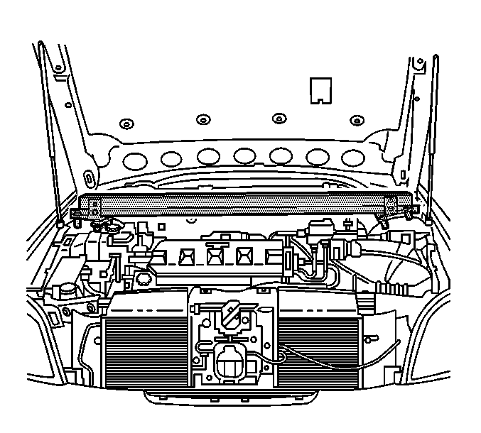
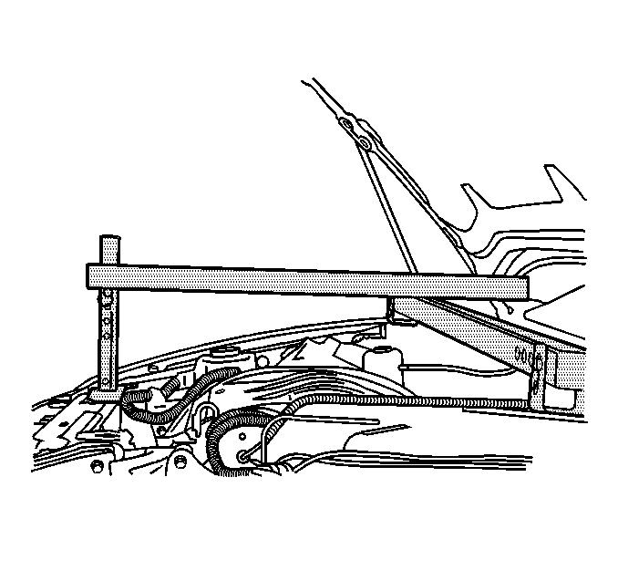
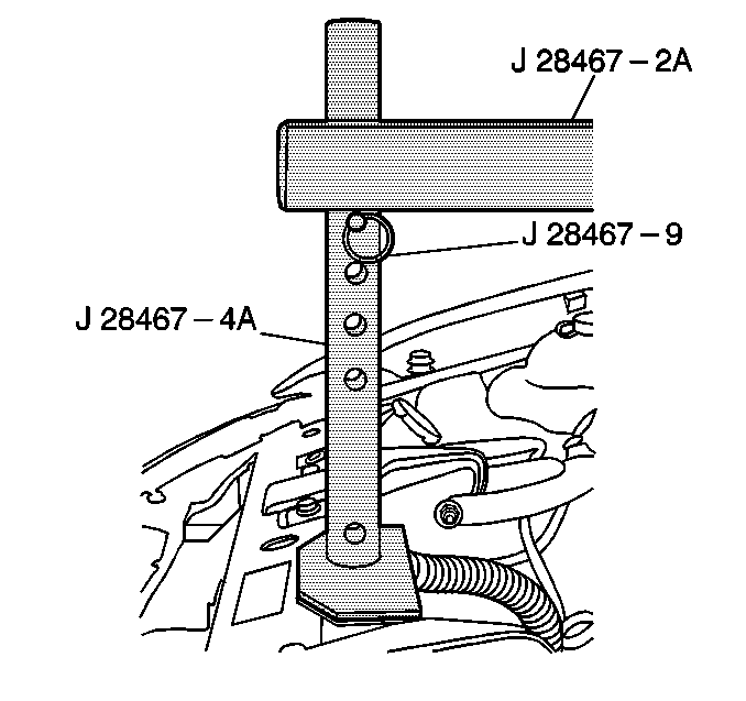
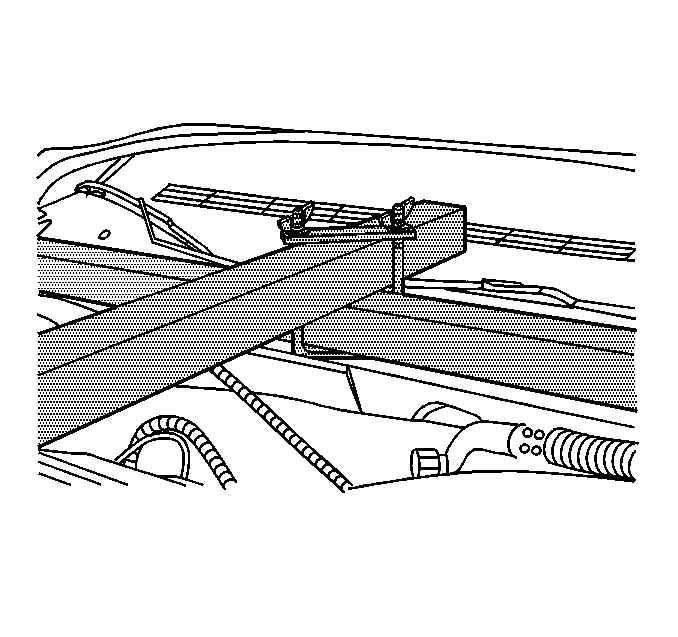
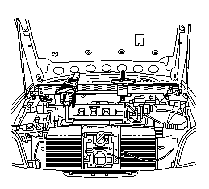
- Install the radiator shelf tube (J 28467-2A) on top of the strut tower tube (J 28467-3) over the J 42504 .
- Install the round tube of the front support assembly (J 28467-4A) through the large hole in the radiator shelf tube (J 28467-2A). The hole used in the radiator shelf tube (J 28467-2A) depends on the vehicle application.
- Place the rubber padded foot of the front support assembly (J 28467-4A) on the upper tie bar.
- Install the 7/16 in. x 2.0 in. quick release pin (J 28467-9) through the hole in the front support assembly (J 28467-4A) in order to level the radiator shelf tube (J 28467-2A).
- Install the cross bracket assembly (J 28467-1A).
- Hand tighten the cross bracket assembly (J 28467-1A) wing nuts.
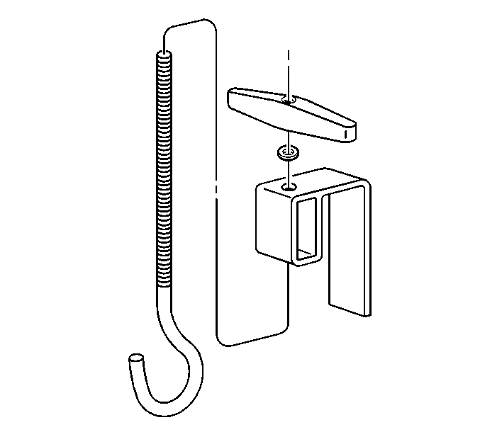
- Install the lift hook (J 28467-7A) through the lift hook bracket (J 28467-6A).
- Install the 1/2 in. lift hook washer and lift hook wing nut (J 28467-34) onto the lift hook (J 28467-7A).
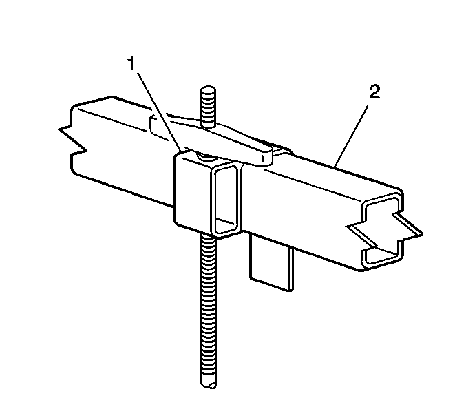
- Install the assembled lift hook bracket (J 28467-6A) (1) over the strut tower tube (J 28467-3) (2).
- Adjust the assembled lift hook bracket (J 28467-6A) (1) in order to align the hook with the rear engine lift hook bracket.
- Install the lift hook (J 28467-7A) through the rear engine lift hook bracket. Ensure the hook does not damage the surrounding components.
- Repeat steps 18 and 19.
- Install the assembled lift hook bracket (J 28467-6A) (1) over the radiator shelf tube (J 28467-2A) (2),
- Adjust the assembled lift hook bracket (J 28467-6A) (1) in order to align the hook with the J 42504 .
- Install the lift hook (J 28467-7A) through the J 42504 . Ensure the hook does not damage the surrounding components.
- Hand tighten the lift hook wing nuts (J 28467-34) securely to remove all slack from the engine support fixture assembly.

Removal Procedure
- Remove the J 28467-B .
- Remove the J 42478 .
- Install the two rearward strut bolts to the right and left strut towers.
- Install the upper filler panel. Refer to Filler Panel Replacement - Upper in Body Front End.
- Install the air inlet grill. Refer to Air Inlet Grille Panel Replacement in Body Front End.
- Remove the J 42504 from the cylinder head.
- Install the bolt bracing the power steering return hose to the cylinder head.

Notice: Use the correct fastener in the correct location. Replacement fasteners must be the correct part number for that application. Fasteners requiring replacement or fasteners requiring the use of thread locking compound or sealant are identified in the service procedure. Do not use paints, lubricants, or corrosion inhibitors on fasteners or fastener joint surfaces unless specified. These coatings affect fastener torque and joint clamping force and may damage the fastener. Use the correct tightening sequence and specifications when installing fasteners in order to avoid damage to parts and systems.
Tighten
Tighten the strut tower bolts to 60 N·m (44 lb ft).


Tighten
Tighten the power steering return hose retaining bolt to 50 N·m (37 lb ft).
