Rear Disc Brake Pads Replacement J55
Caution: Refer to Brake Dust Caution in the Preface section.
Removal Procedure
- Inspect the fluid level in the brake master cylinder reservoir.
- If the brake fluid level is midway between the maximum-full point and the minimum allowable level, no brake fluid needs to be removed from the reservoir before proceeding.
- If the brake fluid level is higher than midway between the maximum-full point and the minimum allowable level, remove brake fluid to the midway point before proceeding.
- Raise the vehicle and suitably support. Refer to Lifting and Jacking the Vehicle in General Information.
- Mark the relationship of the wheel to the axle flange.
- Remove the tire and wheel assembly. Refer to Tire and Wheel Removal and Installation in Tires and Wheels.
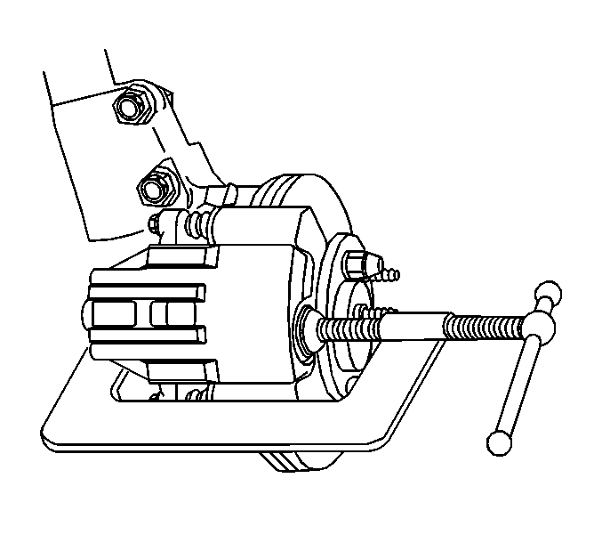
- Install a large C-clamp over the body of the brake caliper with the C-clamp ends against the rear of the caliper body and against the outer brake pad.
- Tighten the C-clamp until the caliper piston is compressed into the caliper bore enough to allow the caliper to slide past the brake rotor.
- Remove the C-clamp from the brake caliper.
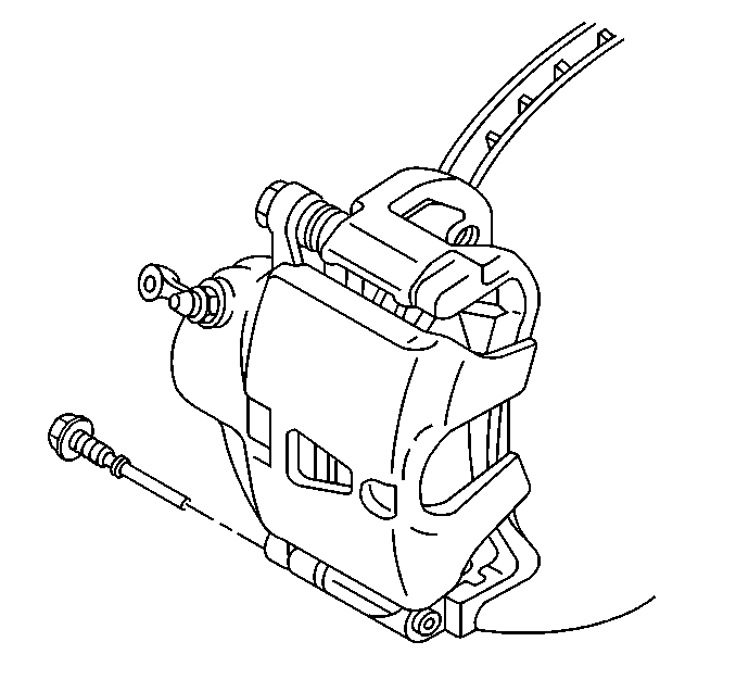
- Remove the lower brake caliper pin bolt.
- Pivot the brake caliper body upward and secure out of the way with heavy mechanic's wire. Do NOT disconnect the hydraulic brake flexible hose from the caliper.
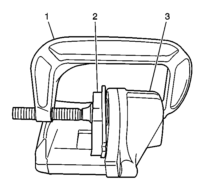
- Install a large C-clamp (1) over the body of the brake caliper (3) with the C-clamp ends against the rear of the caliper body and against an old inner brake pad or a wood block (2) installed against the caliper piston.
- Tighten the C-clamp until the caliper piston is compressed completely into the caliper bore.
- Remove the C-clamp and the old brake pad or wood block from the caliper.
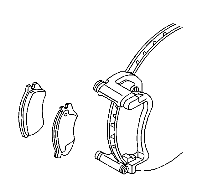
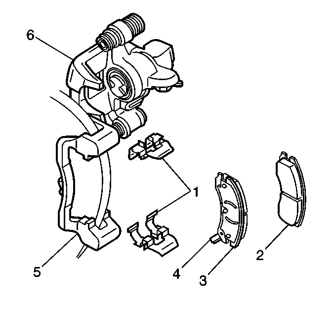
- Remove the inboard and outboard brake pads from the brake caliper bracket.
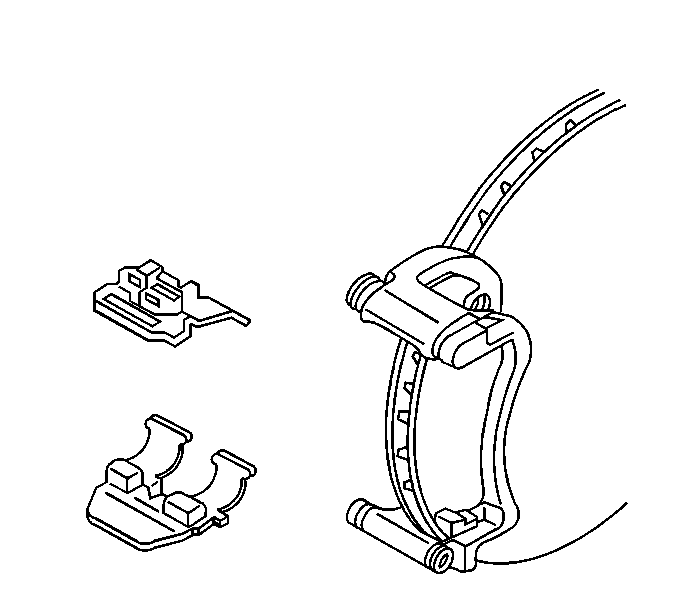
- Remove and inspect the brake pad retainers.
Notice: Support the brake caliper with heavy mechanic wire, or equivalent, whenever it is separated from its mount and the hydraulic flexible brake hose is still connected. Failure to support the caliper in this manner will cause the flexible brake hose to bear the weight of the caliper, which may cause damage to the brake hose and in turn may cause a brake fluid leak.
Installation Procedure
- Inspect the brake caliper bolt suspension boots for cuts, tears, or deterioration. If damaged, replace the pin boots. Refer to Rear Disc Brake Hardware Replacement .
- Inspect the brake caliper pin bolt for damage or corrosion. Replace if damaged or corroded. Do not attempt to clean away corrosion. Corrosion is typically caused by damaged pin boots. Refer to Rear Disc Brake Hardware Replacement .
- Inspect the brake caliper piston boot for deterioration, repair or replace the brake caliper if damaged. Refer to Rear Brake Caliper Overhaul .
- Install the brake pad retainers into the brake caliper bracket.
- Install the inboard and outboard brake pads into the brake caliper bracket.
- Pivot the brake caliper down over the brake pads and into the brake caliper bracket.
- Apply a thin coat of high temperature silicone lube to the rear brake caliper bolts.
- Install the brake caliper pin bolts.
- Install the tire and wheel assembly. Refer to Tire and Wheel Removal and Installation in Tires and Wheels.
- Lower the vehicle.
- With the engine OFF, gradually apply the brake pedal to approximately 2/3 of its travel distance.
- Slowly release the brake pedal.
- Wait 15 seconds, then repeat steps 11-12 until a firm brake pedal apply is obtained; this will properly seat the brake caliper pistons and brake pads.
- Fill the brake master cylinder reservoir to the proper level. Refer to Master Cylinder Reservoir Filling in Hydraulic Brakes .
- Burnish the pads and rotors. Refer to Brake Pad and Rotor Burnishing .
Notice: Use the correct fastener in the correct location. Replacement fasteners must be the correct part number for that application. Fasteners requiring replacement or fasteners requiring the use of thread locking compound or sealant are identified in the service procedure. Do not use paints, lubricants, or corrosion inhibitors on fasteners or fastener joint surfaces unless specified. These coatings affect fastener torque and joint clamping force and may damage the fastener. Use the correct tightening sequence and specifications when installing fasteners in order to avoid damage to parts and systems.
Tighten
Tighten the brake caliper pin bolts to 31 N·m
(23 lb ft).
Rear Disc Brake Pads Replacement without J55
Caution: Refer to Brake Dust Caution in the Preface section.
Removal Procedure
- Inspect the fluid level in the brake master cylinder reservoir.
- If the brake fluid level is midway between the maximum-full point and the minimum allowable level, no brake fluid needs to be removed from the reservoir before proceeding.
- If the brake fluid level is higher than midway between the maximum-full point and the minimum allowable level, remove brake fluid to the midway point before proceeding.
- Raise the vehicle and suitably support. Refer to Lifting and Jacking the Vehicle in General Information.
- Remove the tire and wheel assembly. Refer to Tire and Wheel Removal and Installation in Tires and Wheels.
- Using a large C clamp, compress the brake caliper piston into the brake caliper bore to gain enough clearance to allow the brake caliper to pivot off the brake caliper bracket. Compress the piston until resistance is felt, but no more than 1 mm (0.039 in) of piston travel.
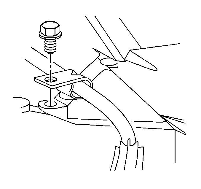
- Remove the park brake cable guide bolt from the lower control arm.
- Remove the bottom brake caliper pin bolt.
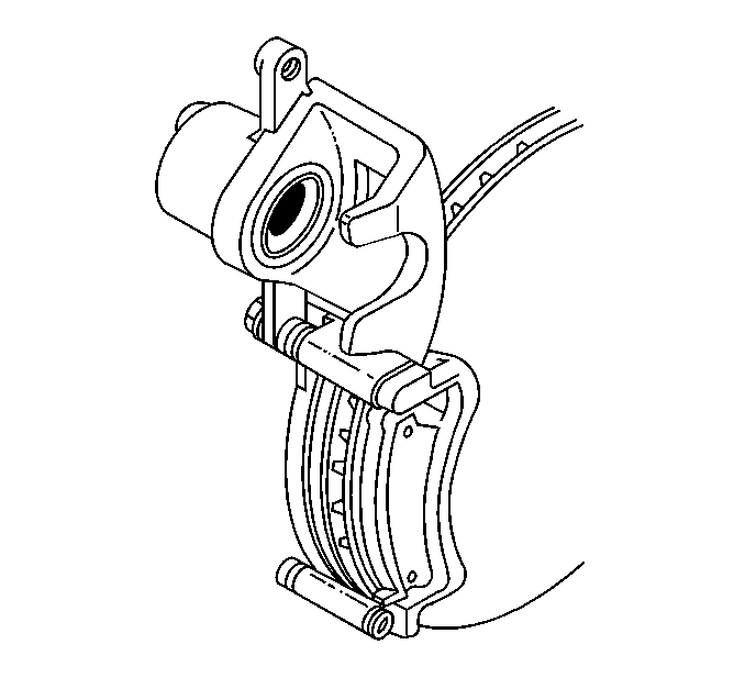
- Pivot the brake caliper body (6) upward and secure out of the way with heavy mechanic's wire. Do NOT disconnect the hydraulic brake flexible hose from the caliper.
- Remove the inboard (2) and outboard (3) brake pads from the brake caliper bracket (5).
- Remove and inspect the brake pad retainers (1).
Notice: When using a large C-clamp to compress a caliper piston into a caliper bore of a caliper equipped with an integral park brake mechanism, do not exceed more than 1 mm (0.039 in) of piston travel. Exceeding this amount of piston travel will cause damage to the internal adjusting mechanism and/or the integral park brake mechanism.
Notice: Support the brake caliper with heavy mechanic wire, or equivalent, whenever it is separated from its mount and the hydraulic flexible brake hose is still connected. Failure to support the caliper in this manner will cause the flexible brake hose to bear the weight of the caliper, which may cause damage to the brake hose and in turn may cause a brake fluid leak.
Installation Procedure
- Inspect the brake caliper bolt suspension boots for cuts, tears, or deterioration. If damaged, replace the brake caliper pin boots.
- Inspect the brake caliper pin bolts for damage or corrosion. Replace if damaged or corroded. Do not attempt to clean away corrosion. Corrosion is typically caused by damaged pin boots. Refer to Rear Disc Brake Mounting and Hardware Inspection .
- Inspect the brake caliper piston boot for deterioration, repair or replace the brake caliper if damaged. Refer to Rear Brake Caliper Replacement .
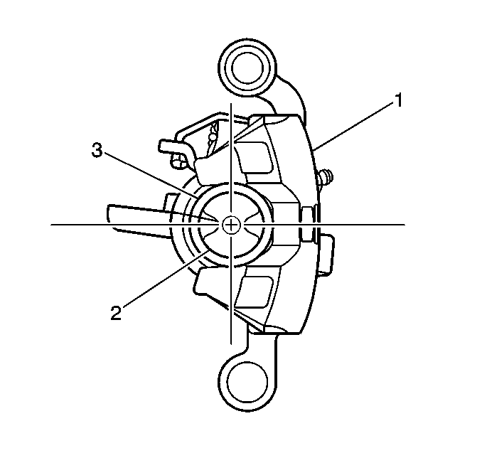
- Retract the brake caliper piston (2) into the brake caliper bore. Use a spanner type wrench to turn the piston (2) clockwise until it bottoms in the brake caliper bore and align the piston.
- Align the cutouts in the brake caliper piston to the alignment pins on the brake pads.
- Apply a thin coat of high temperature silicone lube to the rear brake caliper pin bolts.
- Install the brake pad retainers (1) into the brake caliper bracket (5).
- Install the inboard (2) and outboard (3) brake pads into the brake caliper bracket.
- Pivot the brake caliper down over the brake pads and into the brake caliper bracket.
- Insert the lower brake caliper pin bolt.
- Install the park brake cable guide bolt to the lower control arm.
- Install the tire and wheel assembly. Refer to Tire and Wheel Removal and Installation in Tires and Wheels.
- Lower the vehicle.
- With the engine OFF, gradually apply the brake pedal to approximately 2/3 of its travel distance.
- Slowly release the brake pedal.
- Wait 15 seconds, then repeat steps 14-15 until a firm brake pedal apply is obtained; this will properly seat the brake caliper pistons and brake pads.
- Fill the brake master cylinder reservoir to the proper level. Refer to Master Cylinder Reservoir Filling in Hydraulic Brakes.
- Burnish the pads and rotors. Refer to Brake Pad and Rotor Burnishing .
Notice: Use the correct fastener in the correct location. Replacement fasteners must be the correct part number for that application. Fasteners requiring replacement or fasteners requiring the use of thread locking compound or sealant are identified in the service procedure. Do not use paints, lubricants, or corrosion inhibitors on fasteners or fastener joint surfaces unless specified. These coatings affect fastener torque and joint clamping force and may damage the fastener. Use the correct tightening sequence and specifications when installing fasteners in order to avoid damage to parts and systems.
Tighten
Tighten the brake caliper pin bolt to 26 N·m
(20 lb ft).
Tighten
Tighten the park brake cable guide bolt to 24 N·m
(18 lb ft).
