Caution: Refer to Brake Fluid Irritant Caution in the Preface section.
Notice: Refer to Brake Fluid Effects on Paint and Electrical Components Notice in the Preface section.
Removal Procedure
- Turn OFF the ignition.
- Raise the vehicle. Refer to Lifting and Jacking the Vehicle in General Information.
- Remove the left front wheel. Refer to Tire and Wheel Removal and Installation in Tires and Wheels.
- Remove the left front fascia extension. Refer to Front Bumper Fascia Extension Replacement in Bumpers.
- Thoroughly wash all contaminants from and around the EBCM.
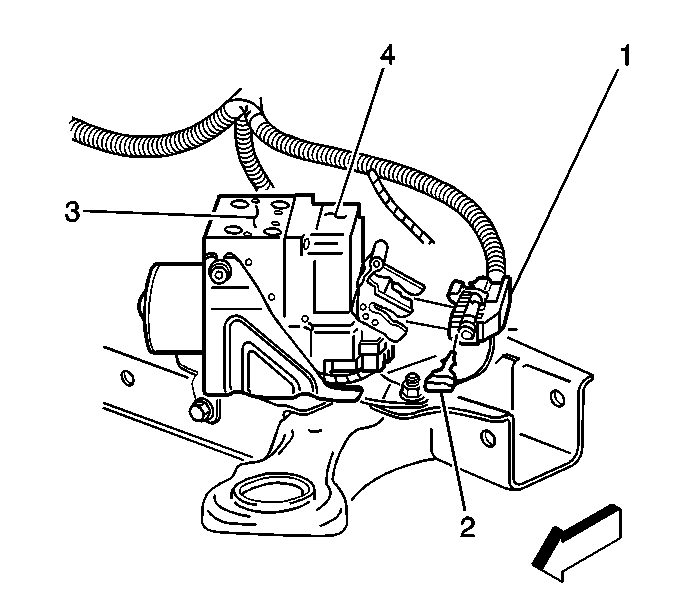
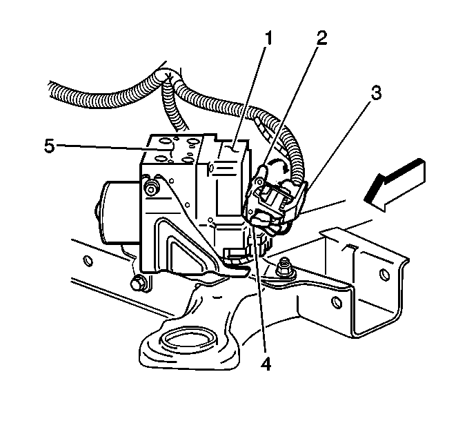
- Remove the EBCM connector position assurance (2) from the EBCM electrical connector (1).
- Rotate the EBCM connector tab up to the unlocked position.
- Disconnect the EBCM electrical connector (1) from the EBCM (4).
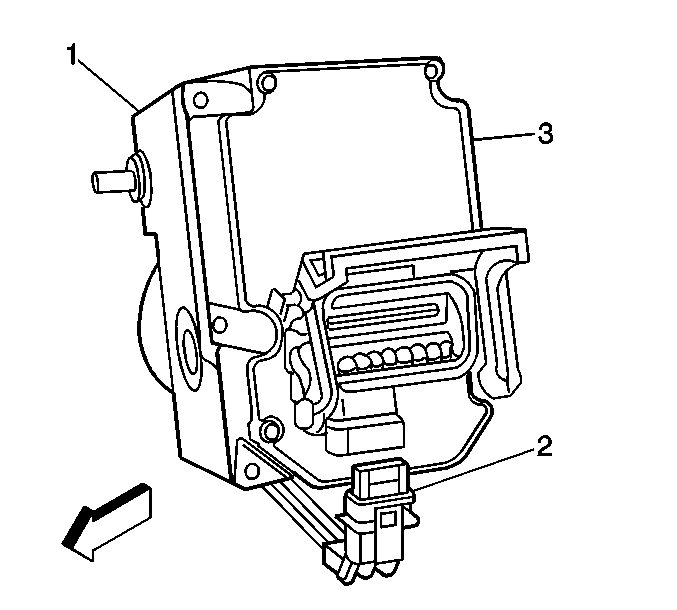
- Disconnect the brake pressure modulator valve (BPMV) pump motor harness pigtail electrical connector (2) from the EBCM (3).
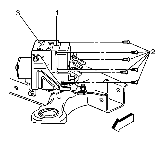
- Remove the 6 EBCM to BPMV screws (2).
- Clean the surface of the EBCM/BPMV assembly.
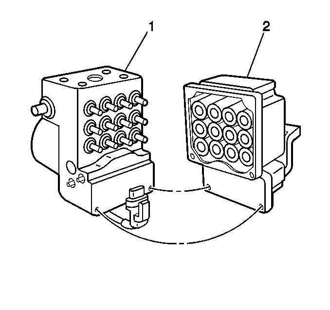
- Separate the EBCM (2) from the BPMV (1).
Important: The area around the electronic brake control module (EBCM) must be free from dirt to prevent contamination of disassembled antilock brake system (ABS) components.
Notice: To prevent equipment damage, never connect or disconnect the wiring harness connection from the EBCM with the ignition switch in the ON position.
Important: The EBCM cannot be repaired. If faulty, the unit must be replaced.
Installation Procedure
- Clean the seal surface of the BPMV.
- Install the EBCM (2) to the BPMV (1).
- Install the 6 EBCM to BPMV screws (2).
- Connect the BPMV pump motor harness pigtail electrical connector (2) to the EBCM (3).
- Connect the EBCM electrical connector (1) to the EBCM (4).
- Rotate the EBCM connector tab (2) down to the locked position.
- Install the EBCM connector position assurance (2) to the EBCM electrical connector (1).
- Install the left front fascia extension. Refer to Front Bumper Fascia Extension Replacement in Bumpers.
- Install the left front wheel. Refer to Tire and Wheel Removal and Installation in Tires and Wheels.
- Lower the vehicle. Refer to Lifting and Jacking the Vehicle in General Information.
- If a replacement EBCM is being installed, it must be programmed using the latest software matching the vehicle. Refer to the Techline Terminal/Equipment user's instructions.
- Use the scan tool in order to clear the DTCs.
- Perform the ABS Diagnostic System Check. Refer to Diagnostic System Check - Vehicle in Vehicle DTC Information.
- Refer to Control Module References for programming and setup information.


Notice: Use the correct fastener in the correct location. Replacement fasteners must be the correct part number for that application. Fasteners requiring replacement or fasteners requiring the use of thread locking compound or sealant are identified in the service procedure. Do not use paints, lubricants, or corrosion inhibitors on fasteners or fastener joint surfaces unless specified. These coatings affect fastener torque and joint clamping force and may damage the fastener. Use the correct tightening sequence and specifications when installing fasteners in order to avoid damage to parts and systems.
Tighten
Tighten the 6 screws to 3.2 N·m (28 lb in).


Notice: To prevent equipment damage, never connect or disconnect the wiring harness connection from the EBCM with the ignition switch in the ON position.
Important: An unprogrammed EBCM will result in the following conditions:
• Inoperative or poorly functioning dynamic rear proportioning (DRP)/ABS/traction control system (TCS)/vehicle stability enhancement system (VSES)/variable effort steering (VES), if equipped • Set DTC C1248 EBCM Turned On the Red Brake Warning Indicator • Set DTC C1255m3 EBCM Internal Malfunction
