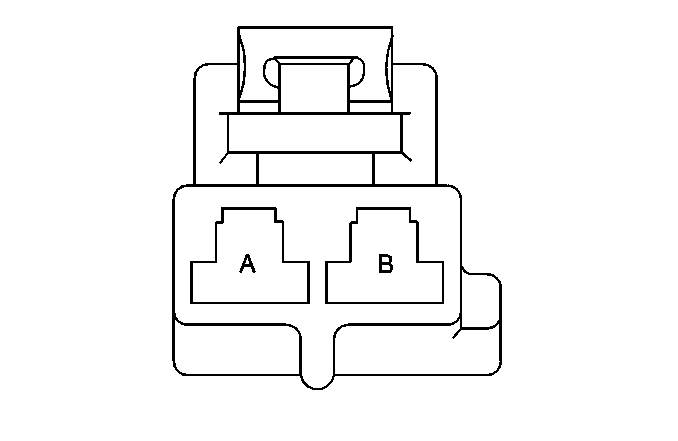
| |||||||
|---|---|---|---|---|---|---|---|
Connector Part Information |
| ||||||
Pin | Wire Color | Circuit No. | Function | ||||
A | BLK/WHT | 651 | Ground | ||||
B | RED | 1242 | Battery Positive Voltage | ||||
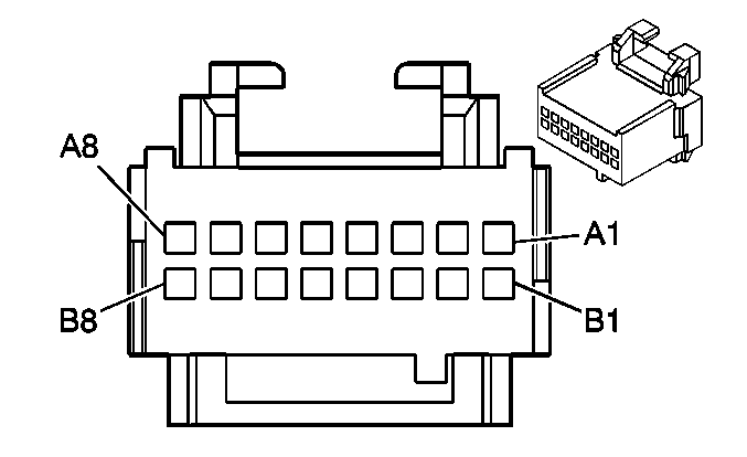
| |||||||
|---|---|---|---|---|---|---|---|
Connector Part Information |
| ||||||
Pin | Wire Color | Circuit No. | Function | ||||
A1 | LT BLU | 1957 | Left Front Midrange Speaker Output (-) | ||||
A2 | DK BLU | 1857 | Left Front Midrange Speaker Output (+) | ||||
A3 | DK GRN | 1953 | Right Front Midrange Speaker Output (-) | ||||
A4 | ORN | 1853 | Right Front Midrange Speaker Output (+) | ||||
A5 | RED | 1955 | Right Rear Midrange Speaker Output (-) | ||||
A6 | TAN | 1855 | Right Rear Midrange Speaker Output (+) | ||||
A7 | WHT | 1959 | Left Rear Midrange Speaker Output (-) | ||||
A8 | TAN | 1859 | Left Rear Midrange Speaker Output (+) | ||||
B1 | DK BLU | 658 | Cellular Telephone Voice Signal | ||||
B2 | LT BLU/BLK | 659 | Cellular Telephone Voice Low Reference | ||||
B3-B8 | -- | -- | Not Used | ||||
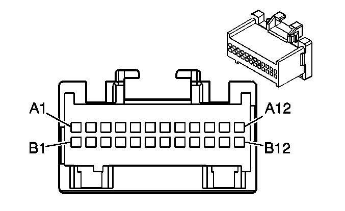
| |||||||
|---|---|---|---|---|---|---|---|
Connector Part Information |
| ||||||
Pin | Wire Color | Circuit No. | Function | ||||
A1 | PPL | 1952 | Right Front Tweeter Speaker Output (-) | ||||
A2 | LT GRN | 1852 | Right Front Tweeter Speaker Output (+) | ||||
A3 | BLK | 1856 | Left Front Tweeter Speaker Output (+) | ||||
A4 | YEL | 1956 | Left Front Tweeter Speaker Output (-) | ||||
A5 | LT GRN/BLK | 1794 | Left Subwoofer Speaker Output (-) | ||||
A6 | DK BLU/WHT | 346 | Left Subwoofer Speaker Output (+) | ||||
A7 | LT BLU | 1960 | Front Center Speaker Output (-) | ||||
A8 | YEL | 1860 | Front Center Speaker Output (+) | ||||
A9 | LT BLU/BLK | 315 | Right Subwoofer Speaker Output (-) | ||||
A10 | DK GRN | 1795 | Right Subwoofer Speaker Output (+) | ||||
A11-A12 | -- | -- | Not Used | ||||
B1 | DK GRN/WHT | 368 | Remote Radio Right Audio Signal | ||||
B2 | BLK/WHT | 372 | Remote Radio Audio Output (-) | ||||
B3 | BRN/WHT | 367 | Remote Radio Left Audio Signal | ||||
B4 | LT GRN | 1948 | Right Front Low Level Audio Signal (-) | ||||
B5 | LT GRN/BLK | 512 | Right Front Low Level Audio Signal (+) | ||||
B6 | DK GRN | 1947 | Left Front Low Level Audio Signal (-) | ||||
B7 | TAN | 511 | Left Front Low Level Audio Signal (+) | ||||
B8 | DK BLU/WHT | 653 | Chime Module Bit 1 Signal | ||||
B9 | PPL/WHT | 652 | Chime Module Bit 2 Signal | ||||
B10 | -- | -- | Not Used | ||||
B11 | PPL | 1807 | Class 2 Serial Data | ||||
B12 | -- | -- | Not Used | ||||
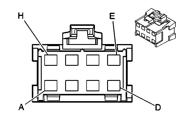
| |||||||
|---|---|---|---|---|---|---|---|
Connector Part Information |
| ||||||
Pin | Wire Color | Circuit No. | Function | ||||
A | BLK | 651 | Ground | ||||
B | DK BLU | 346 | Rear Subwoofer Speaker Output (+) | ||||
C-F | -- | -- | Not Used | ||||
G | LT GRN | 1794 | Rear Subwoofer Speaker Output (-) | ||||
H | RED | 1242 | Battery Positive Voltage | ||||
| |||||||
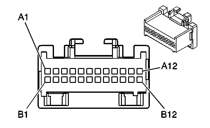
|---|---|---|---|---|---|---|---|
Connector Part Information |
| ||||||
Pin | Wire Color | Circuit No. | Function | ||||
A1 | -- | -- | Not Used | ||||
A2 | WHT | 1959 | Left Rear Midrange Speaker Output (-) | ||||
A3 | TAN | 1859 | Left Rear Midrange Speaker Output (+) | ||||
A4 | BLK | 1856 | Left Front Tweeter Speaker Output (+) | ||||
A5 | YEL | 1956 | Left Front Tweeter Speaker Output (-) | ||||
A6 | LT BLU | 1960 | Front Center Speaker Output (-) | ||||
A7 | YEL | 1860 | Front Center Speaker Output (+) | ||||
A8 | PPL | 1952 | Right Front Tweeter Speaker Output (-) | ||||
A9 | LT GRN | 1852 | Right Front Tweeter Speaker Output (+) | ||||
A10 | TAN | 1855 | Right Rear Midrange Speaker Output (+) | ||||
A11 | RED | 1955 | Right Rear Midrange Speaker Output (-) | ||||
A12 | PPL/WHT | 652 | Chime Module Bit 2 Signal | ||||
B1-B4 | -- | -- | Not Used | ||||
B5 | BRN/WHT | 367 | Remote Radio Left Audio Signal | ||||
B6 | DK GRN/WHT | 368 | Remote Radio Right Audio Signal | ||||
B7 | BLK/WHT | 372 | Remote Radio Audio Output (-) | ||||
B8 | LT GRN | 1948 | Right Front Low Level Audio Signal (-) | ||||
B9 | DK GRN | 1947 | Left Front Low Level Audio Signal (-) | ||||
B10 | TAN | 511 | Left Front Low Level Audio Signal (+) | ||||
B11 | LT GRN/BLK | 512 | Right Front Low Level Audio Signal (+) | ||||
B12 | DK BLU/WHT | 653 | Chime Module Bit 1 Signal | ||||
| |||||||
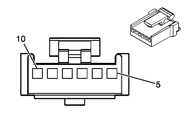
|---|---|---|---|---|---|---|---|
Connector Part Information |
| ||||||
Pin | Wire Color | Circuit No. | Function | ||||
5 | PPL | 1807 | Class 2 Serial Data | ||||
6 | -- | -- | Not Used | ||||
7 | Bare | 1489 | Drain Wire | ||||
8 | DK GRN | 1488 | Noise Reduction Microphone Supply Voltage | ||||
9 | LT BLU/BLK | 659 | Cellular Telephone Voice Low Reference | ||||
10 | DK BLU | 658 | Cellular Telephone Voice Signal | ||||
| |||||||
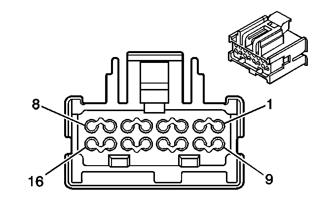
|---|---|---|---|---|---|---|---|
Connector Part Information |
| ||||||
Pin | Wire Color | Circuit No. | Function | ||||
1 | -- | -- | Not Used | ||||
2 | BRN/WHT | 367 | Remote Radio Left Audio Signal | ||||
3 | DK GRN/WHT | 368 | Remote Radio Right Audio Signal | ||||
4-8 | -- | -- | Not Used | ||||
9 | BLK/WHT | 651 | Ground | ||||
10 | BLK/WHT | 372 | Remote Radio Audio Output (-) | ||||
11 | BARE | 1782 | Drain Wire | ||||
12-14 | -- | -- | Not Used | ||||
15 | PPL | 1807 | Class 2 Serial Data | ||||
16 | ORN | 3840 | Battery Positive Voltage | ||||
| |||||||
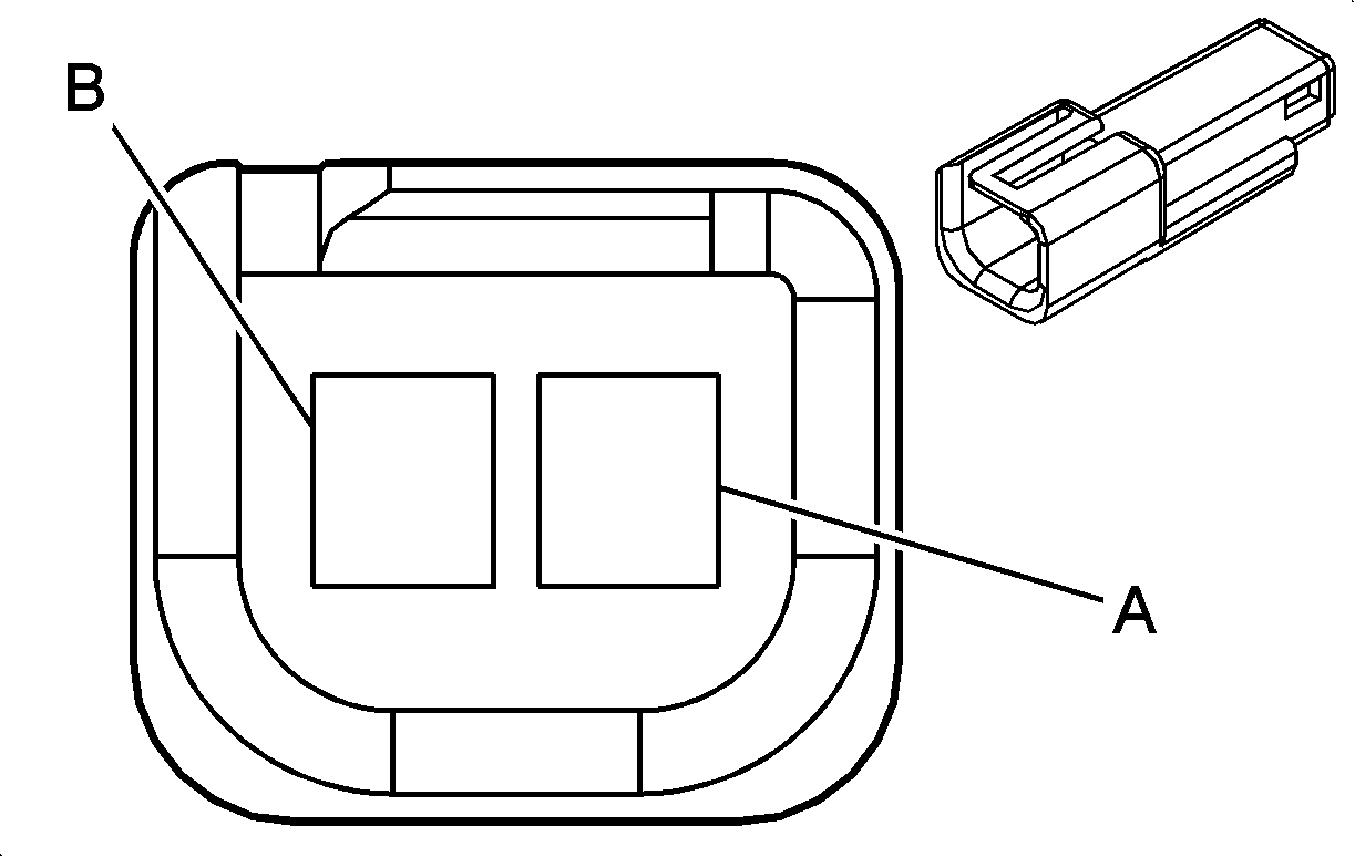
|---|---|---|---|---|---|---|---|
Connector Part Information |
| ||||||
Pin | Wire Color | Circuit No. | Function | ||||
A | BARE | 1489 | Drain Wire | ||||
B | DK GRN | 1488 | Noise Reduction Microphone Supply Voltage | ||||
| |||||||
|---|---|---|---|---|---|---|---|
Connector Part Information |
| ||||||
Pin | Wire Color | Circuit No. | Function | ||||
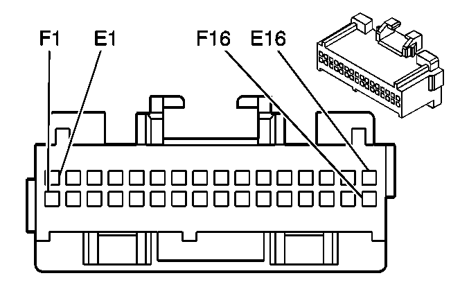
E1 | DK GRN | 835 | Entertainment and Comfort Serial Data | ||||
E2-E3 | -- | -- | Not Used | ||||
E4 | RED | 1486 | FM Composite Signal | ||||
E5 | YEL | 1491 | Backlight Lamps Control | ||||
E6 | PPL | 1807 | Class 2 Serial Data | ||||
E7 | BARE | 814 | Drain Wire (w/UE1 and U43) | ||||
E8 | ORN/BLK | 2360 | Modem Audio Low Reference (w/UE1 and U43) | ||||
E9 | TAN/BLK | 2388 | Modem Audio Return Signal (w/UE1 and U43) | ||||
E10 | BRN/WHT | 2387 | Modem Audio Transmit Signal (w/UE1 and U43) | ||||
E11 | BARE | 814 | Drain Wire (w/UE1 and U43) | ||||
E12 | TAN | 511 | Left Front Low Level Audio Signal (+) | ||||
E13 | DK GRN | 1947 | Left Front Low Level Audio Signal (-) | ||||
E14 | BARE | 2011 | Drain Wire | ||||
E15 | BARE | 2012 | Drain Wire | ||||
E16 | BLK/WHT | 651 | Ground | ||||
F1 | ORN | 2240 | Battery Positive Voltage | ||||
F2 | -- | -- | Not Used | ||||
F3 | WHT | 1487 | Antenna Enable Signal | ||||
F4 | DK GRN/WHT | 817 | Vehicle Speed Signal (w/UE1 and U43) | ||||
F5 | BLK | 450 | Ground | ||||
F6 | PPL | 1807 | Class 2 Serial Data | ||||
F7-F10 | -- | -- | Not Used | ||||
F11 | BARE | 1792 | Drain Wire | ||||
F12 | PPL/WHT | 652 | Chime Module Bit 2 Signal | ||||
F13 | DK BLU/WHT | 653 | Chime Module Bit 1 Signal | ||||
F14 | LT GRN | 1948 | Right Front Low Level Audio Signal (-) | ||||
F15 | LT GRN/BLK | 512 | Right Front Low Level Audio Signal (+) | ||||
F16 | TAN | 2610 | Cellular Microphone Signal (w/UE1 and U43) | ||||

| |||||||
|---|---|---|---|---|---|---|---|
Connector Part Information |
| ||||||
Pin | Wire Color | Circuit No. | Function | ||||
E1 | GRY | 1698 | Antenna Select Supply Voltage (Export) | ||||
E2-E3 | -- | -- | Not Used | ||||
E4 | RED | 1486 | FM Composite Signal | ||||
E5 | -- | -- | Not Used | ||||
E6 | PPL | 1807 | Class 2 Serial Data | ||||
E7- E11 | -- | -- | Not Used | ||||
E12 | TAN | 511 | Left Front Low Level Audio Signal (+) | ||||
E13 | DK GRN | 1947 | Left Front Low Level Audio Signal (-) | ||||
E14 | BARE | 2011 | Drain Wire | ||||
E15 | BARE | 2012 | Drain Wire | ||||
E16 | BLK | 1051 | Ground | ||||
F1 | ORN | 3240 | Battery Positive Voltage | ||||
F2 | DK GRN | 817 | Vehicle Speed Signal | ||||
F3 | WHT | 1487 | Antenna Enable Signal | ||||
F4-F5 | -- | -- | Not Used | ||||
F6 | PPL | 1807 | Class 2 Serial Data | ||||
F7-F10 | -- | -- | Not Used | ||||
F11 | BARE | 1792 | Drain Wire | ||||
F12 | PPL/WHT | 652 | Chime Module Bit 2 Signal | ||||
F13 | DK BLU/WHT | 653 | Chime Module Bit 1 Signal | ||||
F14 | LT GRN | 1948 | Right Front Low Level Audio Signal (-) | ||||
F15 | LT GRN/BLK | 512 | Right Front Low Level Audio Signal (+) | ||||
F16 | -- | -- | Not Used | ||||
| |||||||
|---|---|---|---|---|---|---|---|
Connector Part Information |
| ||||||
Pin | Wire Color | Circuit No. | Function | ||||
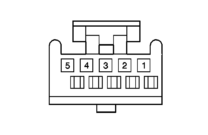
1 | TAN | 2610 | Cellular Microphone Signal | ||||
2 | BARE | 814 | Drain Wire | ||||
3-5 | -- | -- | Not Used | ||||
| |||||||
|---|---|---|---|---|---|---|---|
Connector Part Information |
| ||||||
Pin | Wire Color | Circuit No. | Function | ||||
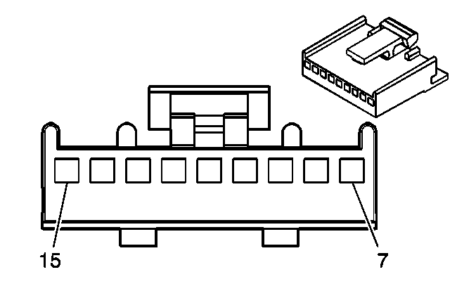
7 | PNK/BLK | 2062 | Navigation Mono Audio Signal (+) | ||||
8 | ORN/BLK | 2061 | Navigation Mono Audio Signal (-) | ||||
9-10 | -- | -- | Not Used | ||||
11 | BARE | 814 | Drain Wire | ||||
12 | BRN/WHT | 2052 | Navigation Left Stereo Audio Signal (+) | ||||
13 | GRY/BLK | 2053 | Navigation Left Stereo Audio Signal (-) | ||||
14 | DK GRN/WHT | 2054 | Navigation Right Stereo Audio Signal (+) | ||||
15 | PPL/WHT | 2055 | Navigation Right Stereo Audio Signal (-) | ||||
| |||||||
|---|---|---|---|---|---|---|---|
Connector Part Information |
| ||||||
Pin | Wire Color | Circuit No. | Function | ||||
1 | -- | -- | Not Used | ||||
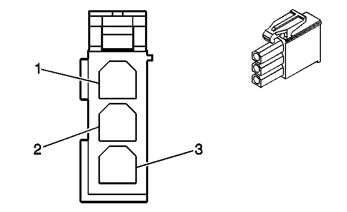
2 | WHT | 1487 | Antenna Enable Signal | ||||
3 | RED | 1486 | FM Composite Signal | ||||
| |||||||
|---|---|---|---|---|---|---|---|
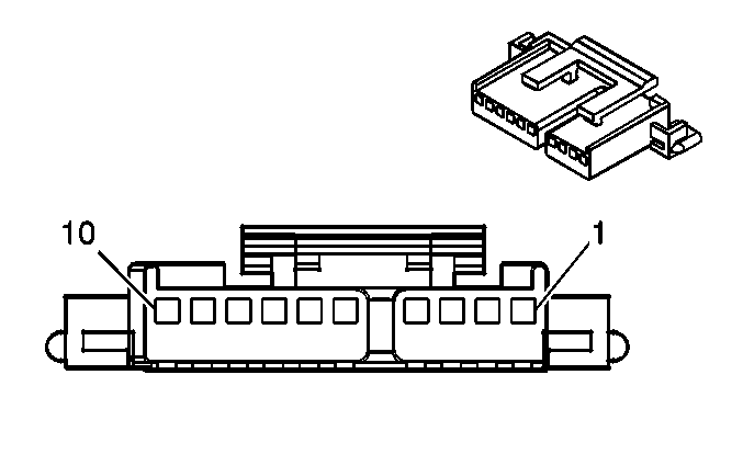
Connector Part Information |
| ||||||
Pin | Wire Color | Circuit No. | Function | ||||
1 | BRN/WHT | 367 | Remote Radio Left Audio Signal | ||||
2 | DK GRN/WHT | 368 | Remote Radio Right Audio Signal | ||||
3 | BLK/WHT | 372 | Remote Radio Audio Output (-) | ||||
4 | BARE | 1782 | Drain Wire | ||||
5 | ORN | 2240 | Battery Positive Voltage | ||||
6 | -- | -- | Not Used | ||||
7 | BLK/WHT | 651 | Ground | ||||
8 | -- | -- | Not Used | ||||
9 | PPL | 1807 | Class 2 Serial Data | ||||
10 | PPL | 1807 | Class 2 Serial Data | ||||
| |||||||
|---|---|---|---|---|---|---|---|
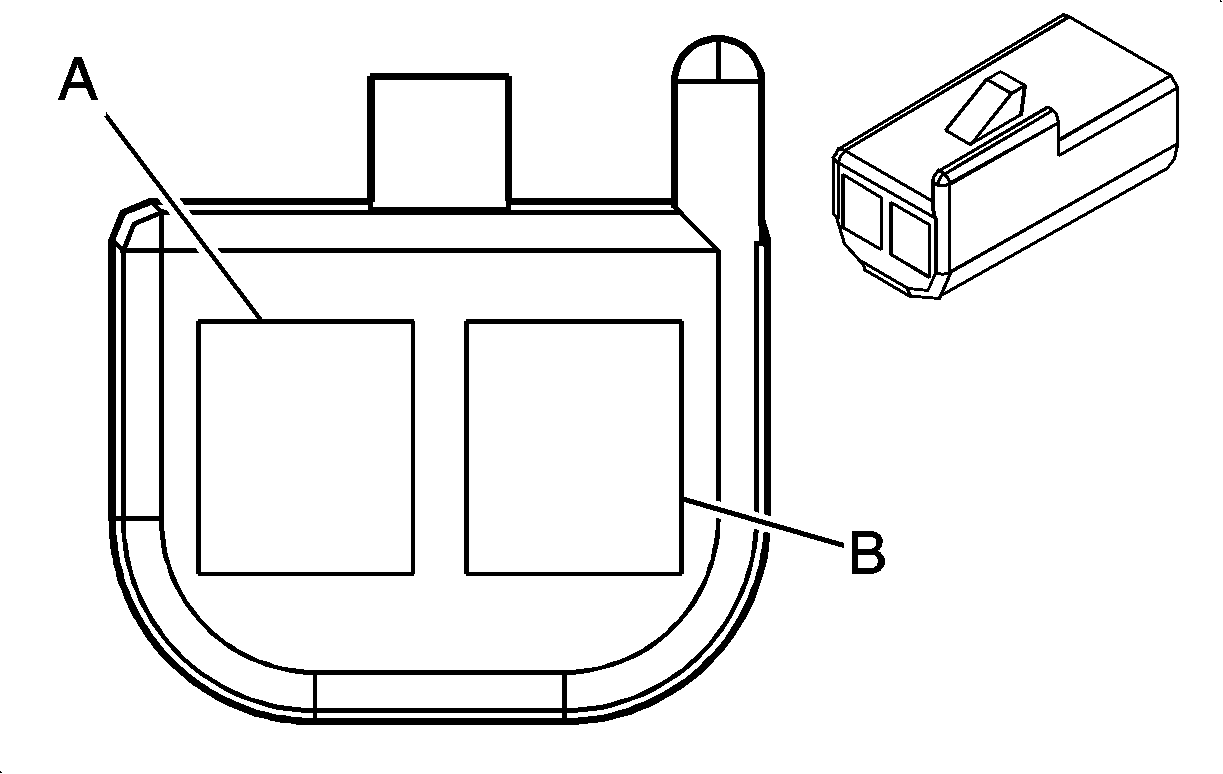
Connector Part Information |
| ||||||
Pin | Wire Color | Circuit No. | Function | ||||
A | LT BLU | 1960 | Front Center Speaker Output (-) | ||||
B | YEL | 1860 | Front Center Speaker Output (+) | ||||
| |||||||
|---|---|---|---|---|---|---|---|
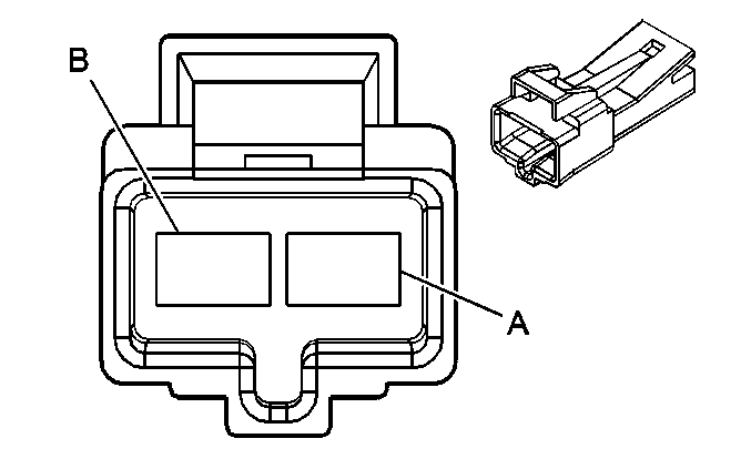
Connector Part Information |
| ||||||
Pin | Wire Color | Circuit No. | Function | ||||
A | YEL | 1956 | Left Front Tweeter Speaker Output (-) | ||||
YEL | 1956 | Left Front Tweeter Speaker Output (-) | |||||
B | BLK | 1856 | Left Front Tweeter Speaker Output (+) | ||||
BLK | 1856 | Left Front Tweeter Speaker Output (+) | |||||
| |||||||
|---|---|---|---|---|---|---|---|
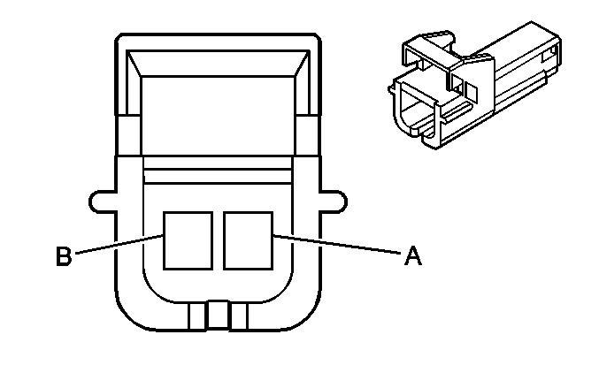
Connector Part Information |
| ||||||
Pin | Wire Color | Circuit No. | Function | ||||
A | YEL | 1956 | Left Front Tweeter Speaker Output (-) | ||||
B | BLK | 1856 | Left Front Tweeter Speaker Output (+) | ||||
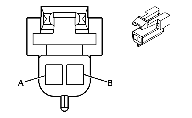
| |||||||
|---|---|---|---|---|---|---|---|
Connector Part Information |
| ||||||
Pin | Wire Color | Circuit No. | Function | ||||
A | YEL | 1956 | Left Front Tweeter Speaker Output (-) | ||||
B | BLK | 1856 | Left Front Tweeter Speaker Output (+) | ||||
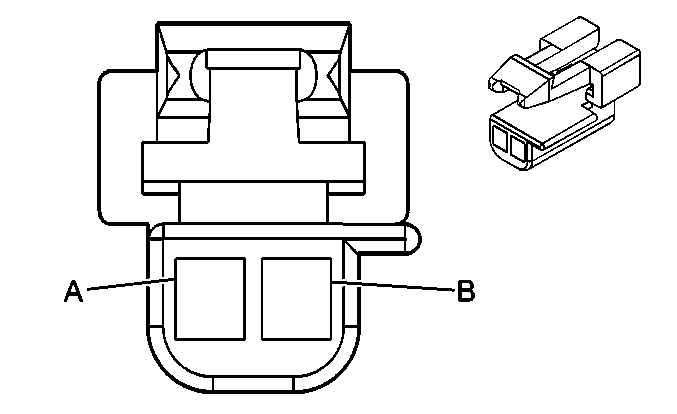
| |||||||
|---|---|---|---|---|---|---|---|
Connector Part Information |
| ||||||
Pin | Wire Color | Circuit No. | Function | ||||
A | LT BLU | 1957 | Left Front Midrange Speaker Output (-) | ||||
B | DK BLU | 1857 | Left Front Midrange Speaker Output (+) | ||||

| |||||||
|---|---|---|---|---|---|---|---|
Connector Part Information |
| ||||||
Pin | Wire Color | Circuit No. | Function | ||||
A | WHT | 1959 | Left Rear Midrange Speaker Output (-) | ||||
B | TAN | 1859 | Left Rear Midrange Speaker Output (+) | ||||
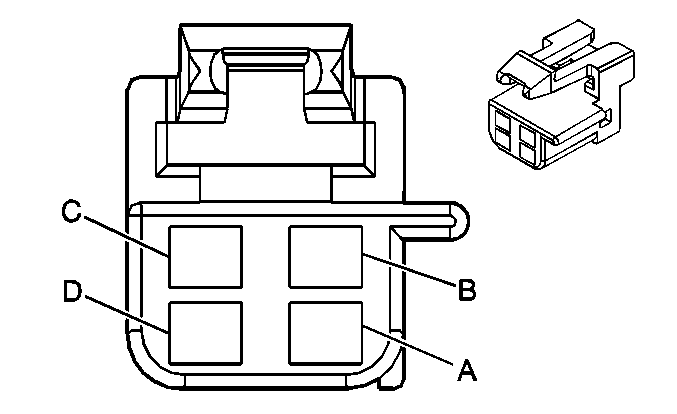
| |||||||
|---|---|---|---|---|---|---|---|
Connector Part Information |
| ||||||
Pin | Wire Color | Circuit No. | Function | ||||
A | LT GRN/BLK | 1794 | Left Subwoofer Speaker Output (-) | ||||
B | DK BLU/WHT | 346 | Left Subwoofer Speaker Output (+) | ||||
C | LT BLU/BLK | 315 | Right Subwoofer Speaker Output (-) | ||||
D | DK GRN | 1795 | Right Subwoofer Speaker Output (+) | ||||
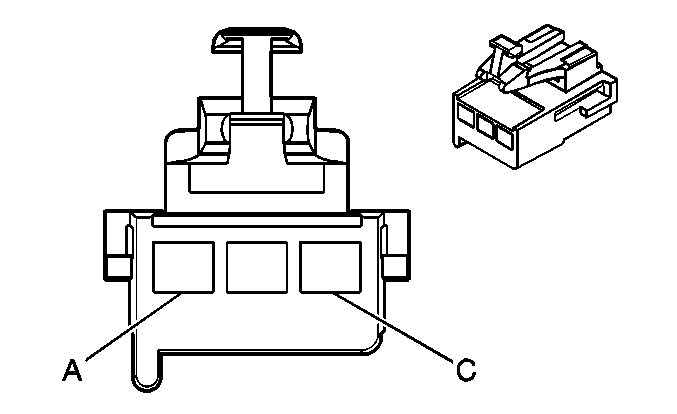
| |||||||
|---|---|---|---|---|---|---|---|
Connector Part Information |
| ||||||
Pin | Wire Color | Circuit No. | Function | ||||
A | DK BLU | 346 | Rear Subwoofer Speaker Output (+) | ||||
B | BLK/WHT | 751 | Ground | ||||
C | LT GRN | 1794 | Rear Subwoofer Speaker Output (-) | ||||

| |||||||
|---|---|---|---|---|---|---|---|
Connector Part Information |
| ||||||
Pin | Wire Color | Circuit No. | Function | ||||
A | PPL | 1952 | Right Front Tweeter Speaker Output (-) | ||||
A | PPL | 1952 | Right Front Tweeter Speaker Output (-) | ||||
B | LT GRN | 1852 | Right Front Tweeter Speaker Output (+) | ||||
B | LT GRN | 1852 | Right Front Tweeter Speaker Output (+) | ||||

| |||||||
|---|---|---|---|---|---|---|---|
Connector Part Information |
| ||||||
Pin | Wire Color | Circuit No. | Function | ||||
A | DK GRN | 1953 | Right Front Midrange Speaker Output (-) | ||||
B | ORN | 1853 | Right Front Midrange Speaker Output (+) | ||||

| |||||||
|---|---|---|---|---|---|---|---|
Connector Part Information |
| ||||||
Pin | Wire Color | Circuit No. | Function | ||||
A | PPL | 1952 | Right Front Tweeter Speaker Output (-) | ||||
B | LT GRN | 1852 | Right Front Tweeter Speaker Output (+) | ||||

| |||||||
|---|---|---|---|---|---|---|---|
Connector Part Information |
| ||||||
Pin | Wire Color | Circuit No. | Function | ||||
A | WHT | 1955 | Right Rear Midrange Speaker Output (-) | ||||
B | TAN | 1855 | Right Rear Midrange Speaker Output (+) | ||||
| |||||||
|---|---|---|---|---|---|---|---|
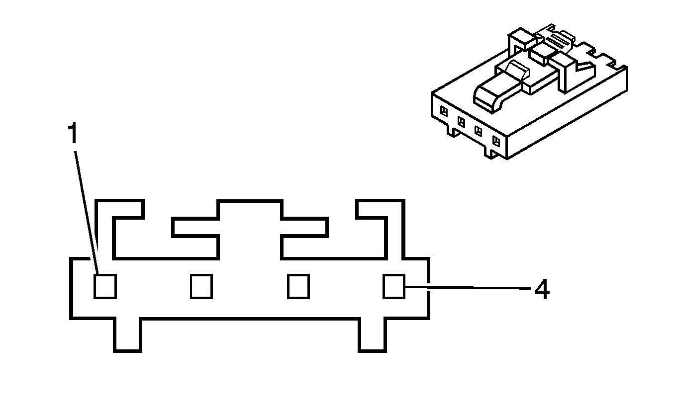
Connector Part Information |
| ||||||
Pin | Wire Color | Circuit No. | Function | ||||
1 | PNK | 1039 | Ignition 1 Voltage | ||||
2 | GRY | 397 | Cruise Control On Switch Signal | ||||
3 | BLK | 350 | Ground | ||||
4 | YEL/BLK | 1491 | Backlight Lamps Control | ||||
| |||||||
|---|---|---|---|---|---|---|---|
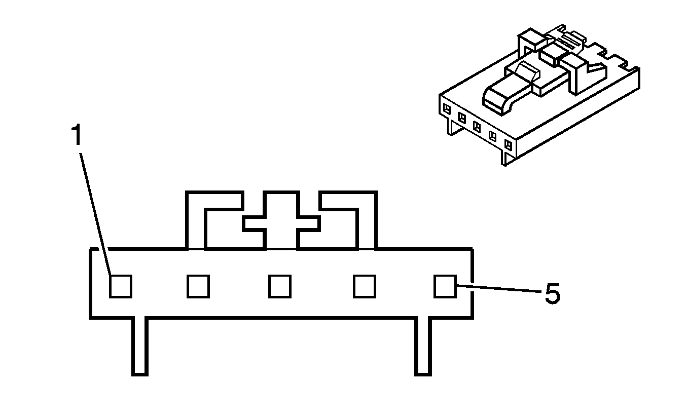
Connector Part Information |
| ||||||
Pin | Wire Color | Circuit No. | Function | ||||
1 | DK BLU | 1796 | Steering Wheel Controls Signal | ||||
2 | YEL/BLK | 1491 | Backlight Lamps Control | ||||
3 | BLK | 350 | Ground | ||||
4 | -- | -- | Not Used | ||||
5 | DK BLU | 1796 | Steering Wheel Controls Signal | ||||
| |||||||
|---|---|---|---|---|---|---|---|
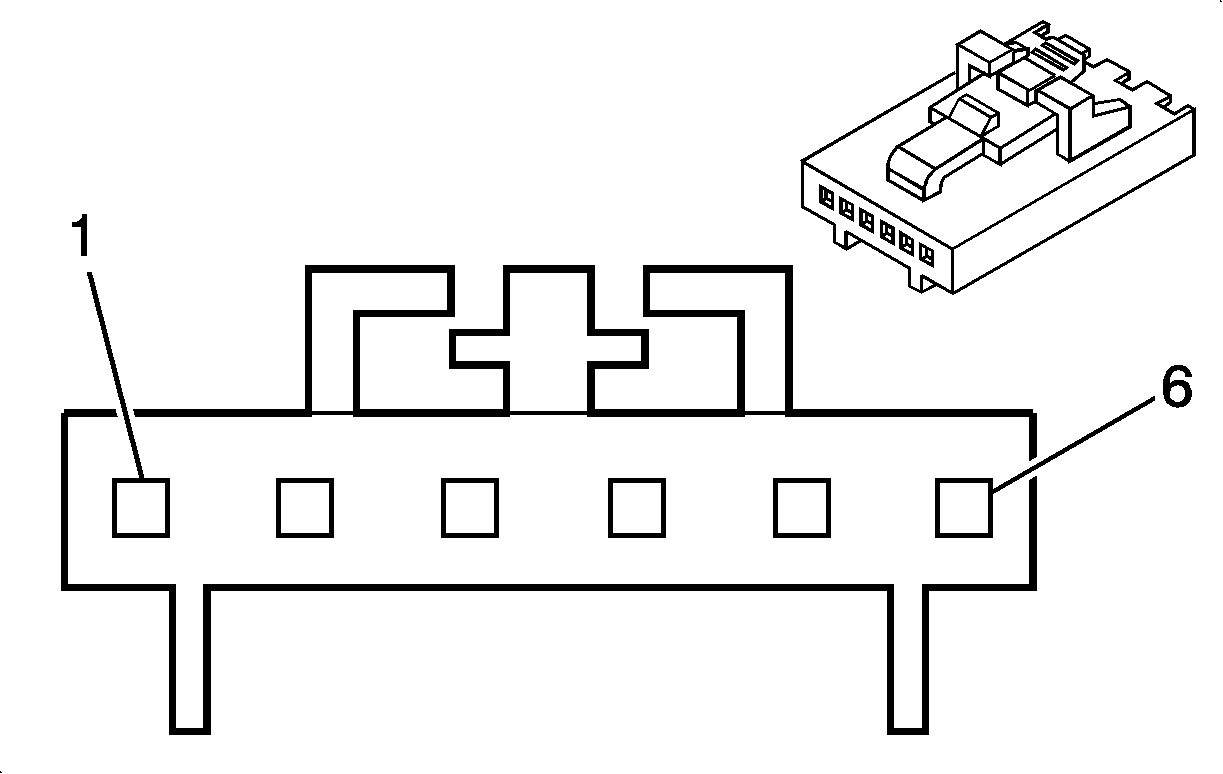
Connector Part Information |
| ||||||
Pin | Wire Color | Circuit No. | Function | ||||
1 | PPL | 1375 | Remote Radio Control Supply Voltage | ||||
2 | DK BLU | 1796 | Steering Wheel Controls Signal | ||||
3 | YEL | 1491 | Backlight Lamps Control | ||||
4 | -- | -- | Not Used | ||||
5 | BLK | 350 | Ground | ||||
6 | DK BLU | 1796 | Steering Wheel Controls Signal | ||||

| |||||||
|---|---|---|---|---|---|---|---|
Connector Part Information |
| ||||||
Pin | Wire Color | Circuit No. | Function | ||||
1 | GRY | 397 | Cruise Control On Switch Signal | ||||
2 | BLK | 350 | Ground | ||||
3 | YEL/BLK | 1491 | Backlight Lamps Control | ||||
4 | GRY/BLK | 87 | Cruise Control Resume/Accel Switch Signal | ||||
5 | DK BLU | 84 | Cruise Control Set/Coast Switch Signal | ||||
