Steering Shaft Upper Bearing Replacement Power Tilt\\ Telescope, Column Shift
Tools Required
J 21854-01
Pivot Pin Remover
Removal Procedure
Caution: Refer to SIR Caution in the Preface section.
- Disable the SIR system. Refer to
SIR Disabling and Enabling
in SIR.
- Remove the steering wheel from the steering column. Refer to
Steering Wheel Replacement
.
- Remove the steering column from the vehicle. Refer to
Steering Column Replacement
.
- Remove the steering wheel theft deterrent lock assembly. Refer to
Theft Deterrent Module Replacement
.
- Remove the linear shift assembly, shift lever, and the A/T shift lock control only. Refer to
Linear Shift Assembly Replacement
.
- Remove the turn signal and multifunction switch assembly only. Refer to
Turn Signal Multifunction Switch Replacement
.
- Remove the tilt spring. Refer to
Steering Column Tilt Spring Replacement
.
- Remove the wire harness assembly only. Refer to
Steering Column Wiring Harness Assembly Replacement
.
- Remove the telescope drive motor assembly and cable only. Refer to
Telescope Actuator Assembly Replacement
.
- Remove the tilt drive motor assembly and cable only. Refer to
Tilt Motor Replacement
.
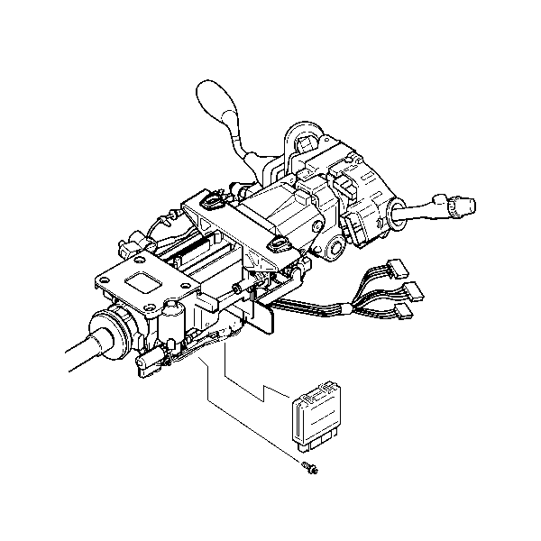
- Remove 1 TORX® head screw from the tilt and telescope module.
- Slide the control module out from the steering column.
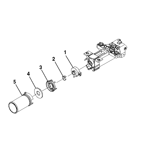
- Remove the following components:
| 13.2. | The steering shaft seal (4) |
| 13.3. | The sensor retainer (3) |
| 13.4. | The sensor locator (2) |
- Remove the steering wheel position sensor (1). Refer to
Steering Wheel Position Sensor Centering
.
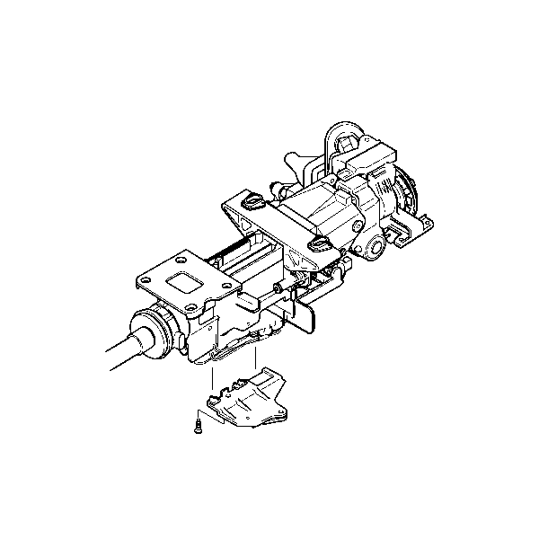
- Remove 1 TORX® head screw from the bottom of the gearshift and tilt motor bracket.
- Remove the bracket.
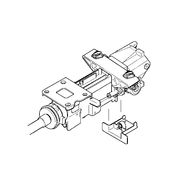
- Gently pry the lower shield assembly off of the steering column.
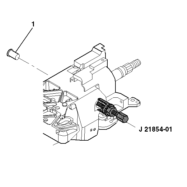
- Remove 2 pivot pins (1) from the steering column support assembly
using
J 21854-01
.
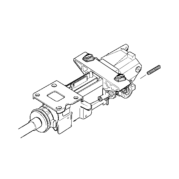
- Unscrew the lead screw.
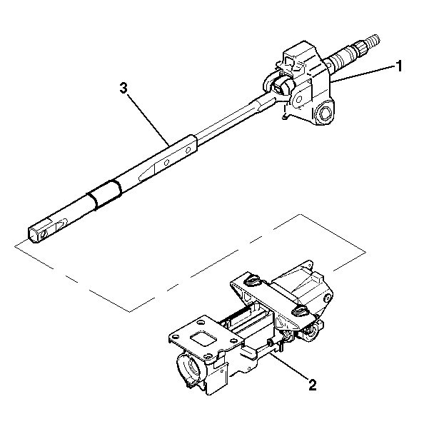
- Remove the tilt head assembly (1) from the steering column support assembly (2) with the steering
shaft (3) still attached.
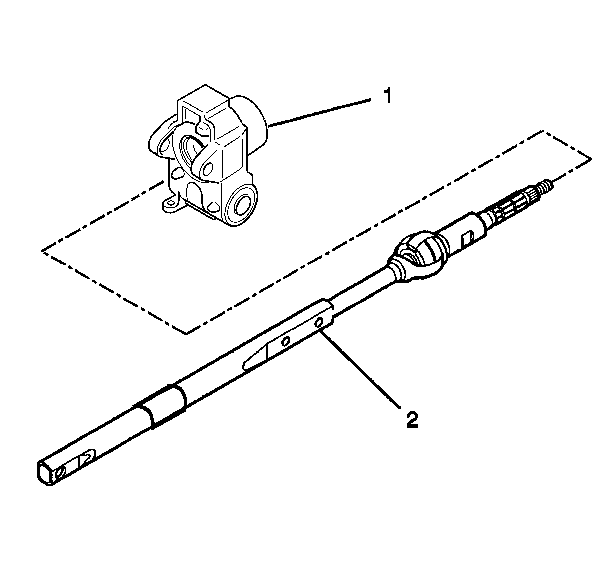
- Remove the tilt head assembly (1) from the steering shaft assembly (2).
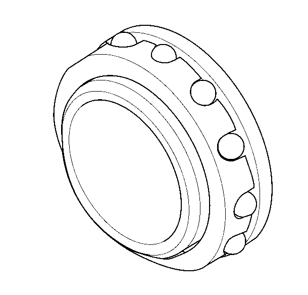
- Remove the bearing assembly from the tilt head assembly.
Installation Procedure

- Install the bearing assembly into the tilt head assembly.

- Install the steering shaft assembly (2) into the tilt head assembly (1).

- Install the steering column tilt head assembly (1) and the steering shaft assembly (3) into
the steering column jacket assembly (2).

- Screw in the lead screw.
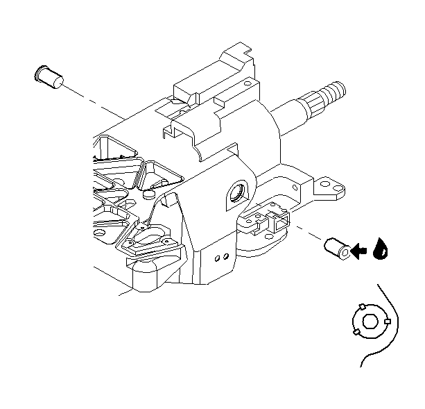
- Lubricate the pivot pins with GM P/N 12345718 (Canadian P/N 10953516).
Install the 2 pivot pins onto the steering column support assembly.

- Align and snap the lower shield assembly onto the steering column.

- Install the bracket.
Notice: Refer to Fastener Notice in the Preface section.
- Install 1 TORX® head screw to the bottom of the gearshift and tilt motor bracket.
Tighten
Tighten the screw to 3 N·m (27 lb in).

- Install the following components:
| 9.2. | The sensor locator (2) |
| 9.3. | The sensor retainer (3) |
| 9.4. | The steering shaft seal (4) |

- Slide the control module into position.
- Install 1 retaining screw.
Tighten
Tighten the screw to 5 N·m (44 lb in).
Caution: Improper routing of the wire harness assembly may damage the inflatable
restraint steering wheel module coil. This may result in a malfunction of
the coil, which may cause personal injury.
- Install the tilt drive motor assembly and cable only. Refer to
Tilt Motor Replacement
.
- Install the telescope drive motor assembly and cable only. Refer to
Telescope Actuator Assembly Replacement
.
- Install the tilt spring. Refer to
Steering Column Tilt Spring Replacement
.
- Install the turn signal and multifunction switch assembly only. Refer to
Turn Signal Multifunction Switch Replacement
.
- Install the linear shift assembly, shift lever and the A/T shift lock control only. Refer to
Linear Shift Assembly Replacement
.
- Install the wire harness assembly only. Refer to
Steering Column Wiring Harness Assembly Replacement
.
- Install the steering wheel theft deterrent lock assembly. Refer to
Theft Deterrent Module Replacement
.
- Install the steering column into the vehicle. Refer to
Steering Column Replacement
.
- Install the steering wheel onto the steering column. Refer to
Steering Wheel Replacement
.
- Enable the SIR system. Refer to
SIR Disabling and Enabling
in SIR.
Steering Shaft Upper Bearing Replacement Power Tilt\\ Telescope, Floor Shift
Tools Required
J 21854-01
Pivot Pin Remover
Removal Procedure
Caution: Refer to SIR Caution in the Preface section.
- Disable the SIR coil. Refer to
SIR Disabling and Enabling
in SIR.
- Remove the steering wheel from the column. Refer to
Steering Wheel Replacement
.
- Remove the steering column from the vehicle. Refer to
Steering Column Replacement
.
- Remove the steering wheel theft deterrent lock assembly. Refer to
Theft Deterrent Module Replacement
.
- Remove the turn signal and multifunction switch assembly only. Refer to
Turn Signal Multifunction Switch Replacement
.
- Remove the tilt spring. Refer to
Steering Column Tilt Spring Replacement
.
- Remove the wire harness assembly only. Refer to
Steering Column Wiring Harness Assembly Replacement
.
- Remove the telescope drive motor assembly and cable only. Refer to
Telescope Actuator Assembly Replacement
.
- Remove the tilt drive motor assembly and cable only. Refer to
Tilt Motor Replacement
.
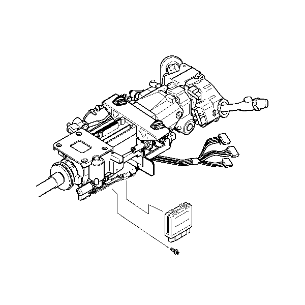
- Remove 1 TORX® head screw from the control module.
- Slide the control module out from the steering column.
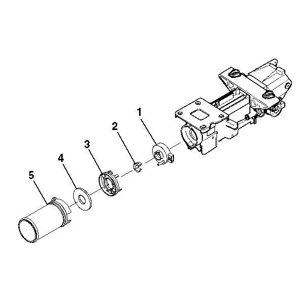
- Remove the following components:
| 12.2. | The steering shaft seal (4) |
| 12.3. | The sensor retainer (3) |
| 12.4. | The sensor locator (2) |
- Remove the steering wheel position sensor (1)-- Refer to
Steering Wheel Position Sensor Centering
.
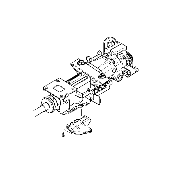
- Remove 1 TORX® head screw from the bottom of the gearshift and tilt motor bracket.
- Remove the bracket.

- Gently pry the lower shield assembly off of the steering column.

- Remove 2 pivot pins (1) from the steering column support assembly
using
J 21854-01
.

- Unscrew the lead screw.

- Remove the tilt head assembly (1) from the steering column support assembly (2) with the steering shaft (3)
still attached.

- Remove the tilt head assembly (1) from the steering shaft assembly (2).

- Remove the bearing assembly from the tilt head assembly.
Installation Procedure

- Install the bearing assembly into the tilt head assembly.

- Install the steering shaft assembly (2) into the tilt head assembly (1).

- Install the tilt head assembly (1) and the steering shaft assembly (3) into the jacket assembly (2).

- Install the lead screw.
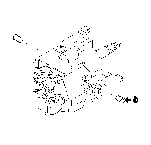
- Lubricate the pivot pins with GM P/N 12345718 (Canadian P/N 10953516).
Install the 2 pivot pins onto the steering column
support assembly.

- Align and snap the lower shield assembly onto the steering column.

- Install the bracket.
Notice: Refer to Fastener Notice in the Preface section.
- Install 1 TORX® head screw to the bottom of the gearshift and tilt motor bracket.
Tighten
Tighten the screw to 3 N·m (26 lb in).

- Install the following components:
| 9.2. | The sensor locator (2) |
| 9.3. | The sensor retainer (3) |
| 9.4. | The steering shaft seal (4) |

- Slide the control module into position.
- Install 1 retaining screw.
Tighten
Tighten the screw to 5 N·m (44 lb in).
Caution: Improper routing of the wire harness assembly may damage the inflatable
restraint steering wheel module coil. This may result in a malfunction of
the coil, which may cause personal injury.
- Install the tilt drive motor assembly and cable only. Refer to
Tilt Motor Replacement
.
- Install the tilt spring. Refer to
Steering Column Tilt Spring Replacement
.
- Install the telescope drive motor assembly and cable only. Refer to
Telescope Actuator Assembly Replacement
.
- Install the turn signal and multifunction switch assembly only. Refer to
Turn Signal Multifunction Switch Replacement
.
- Install the wire harness assembly only. Refer to
Steering Column Wiring Harness Assembly Replacement
.
- Install the steering wheel theft deterrent lock assembly. Refer to
Theft Deterrent Module Replacement
.
- Install the steering column into the vehicle. Refer to
Steering Column Replacement
.
- Install the steering wheel onto the steering column. Refer to
Steering Wheel Replacement
.
- Enable the SIR system. Refer to
SIR Disabling and Enabling
in SIR.
Steering Shaft Upper Bearing Replacement Manual Tilt, Floor Shift
Tools Required
J 21854-01
Pivot Pin Remover
Removal Procedure
Caution: Refer to SIR Caution in the Preface section.
- Disable the SIR coil. Refer to
SIR Disabling and Enabling
in SIR.
- Remove the steering wheel from the column. Refer to
Steering Wheel Replacement
.
- Remove the steering column from the vehicle. Refer to
Steering Column Replacement
.
- Inspect the steering column for accident damage. Refer to
Steering Column Accident Damage Inspection
.
- Remove the steering wheel theft deterrent lock assembly. Refer to
Theft Deterrent Module Replacement
.
- Remove the wire harness assembly only. Refer to
Steering Column Wiring Harness Assembly Replacement
.
- Remove the turn signal and multifunction switch assembly only. Refer to
Turn Signal Multifunction Switch Replacement
.
- Remove the tilt spring. Refer to
Steering Column Tilt Spring Replacement
.
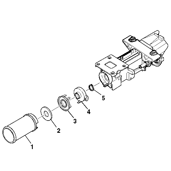
- Remove the following parts from the steering column support assembly:
| 9.2. | The steering shaft seal (2) |
| 9.3. | The sensor retainer (3) |
| 9.5. | The retaining ring (5) |

- Remove the 2 pivot pins (1) from the steering column support assembly
using
J 21854-01
.
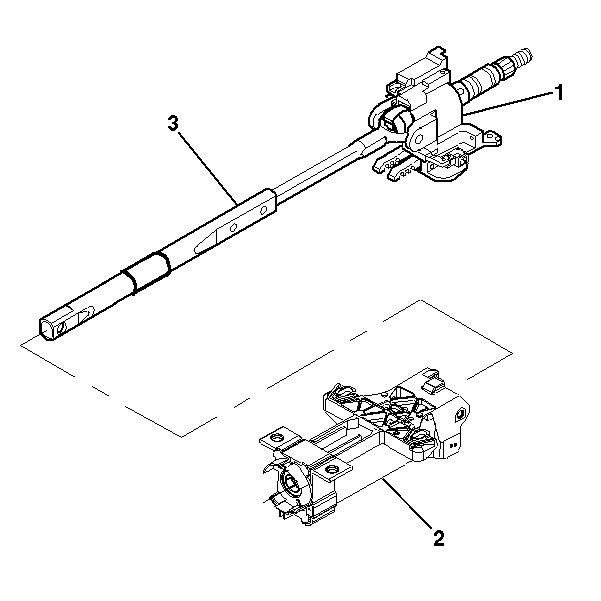
- Remove the tilt head assembly (1) from the steering column support assembly (2) with the steering shaft (3) still attached.
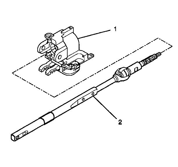
- Remove the tilt head assembly (1) from the steering shaft assembly (2).

- Remove the bearing assembly from the tilt head assembly.
Installation Procedure

- Install the bearing assembly into the tilt head assembly.

- Install the steering shaft assembly (2) into the tilt head assembly (1).

- Install the steering column tilt head assembly (1) and the steering shaft assembly (3) into the steering column support assembly (2).

Important: Replace the steering column support assembly if the steering column support assembly has been staked 3 times.
- Lubricate the pivot pins with GM P/N 12346293 (Canadian P/N 992723).
Install the 2 pivot pins onto the steering column support assembly.
Stake the pins in 3 places.

- Install the following parts onto the steering column support assembly:
| 5.1. | The retaining ring (5) |
| 5.3. | The sensor retainer (3) |
| 5.4. | The steering shaft seal (2) |
Caution: Improper routing of the wire harness assembly may damage the inflatable
restraint steering wheel module coil. This may result in a malfunction of
the coil, which may cause personal injury.
- Install the turn signal and multifunction switch assembly only. Refer to
Turn Signal Multifunction Switch Replacement
.
- Install the wire harness assembly only. Refer to
Steering Column Wiring Harness Assembly Replacement
.
- Install the tilt spring only. Refer to
Steering Column Tilt Spring Replacement
.
- Install the steering wheel theft deterrent lock assembly. Refer to
Theft Deterrent Module Replacement
.
- Install the steering column into the vehicle. Refer to
Steering Column Replacement
.
- Install the steering wheel onto the steering column. Refer to
Steering Wheel Replacement
.
- Enable the SIR system. Refer to
SIR Disabling and Enabling
in SIR.
Steering Shaft Upper Bearing Replacement Manual Tilt, Column Shift
Tools Required
J 21854-01
Pivot Pin Remover
Removal Procedure
Caution: Refer to SIR Caution in the Preface section.
- Disable the SIR coil. Refer to
SIR Disabling and Enabling
in SIR.
- Remove the steering wheel from the column. Refer to
Steering Wheel Replacement
.
- Remove the steering column from the vehicle. Refer to
Steering Column Replacement
.
- Remove the steering wheel theft deterrent lock assembly. Refer to
Theft Deterrent Module Replacement
.
- Remove the wire harness assembly only. Refer to
Steering Column Wiring Harness Assembly Replacement
.
- Remove the turn signal and multifunction switch assembly only. Refer to
Turn Signal Multifunction Switch Replacement
.
- Remove the tilt spring. Refer to
Steering Column Tilt Spring Replacement
.
- Remove the linear shift assembly, the A/T shift lock control assembly, and the shift lever only. Refer to
Linear Shift Assembly Replacement
.
- Remove the tilt spring only. Refer to
Steering Column Tilt Spring Replacement
.

- If a steering shaft position sensor is present, remove the following parts from the steering column support
assembly:
| 10.2. | The steering shaft seal (2) |
| 10.3. | The sensor retainer (3) |
| 10.5. | The retaining ring (5) |
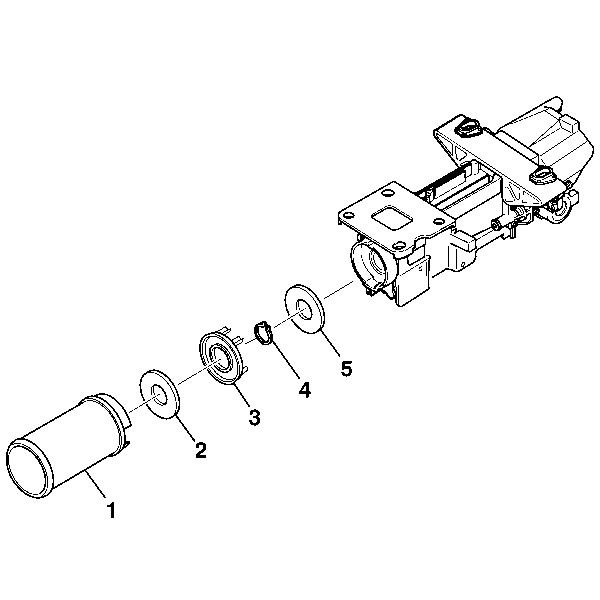
- Remove the following parts from the steering column support assembly:
| 11.2. | The steering shaft seal (2) |
| 11.3. | The sensor retainer (3) |
| 11.4. | The retaining ring (4) |

- Remove the 2 pivot pins (1) from the steering column support assembly
using
J 21854-01
.

- Remove the tilt head assembly (1) from the steering column support assembly (2) with the steering shaft (3) still attached.

- Remove the tilt head assembly (1) from the steering shaft assembly (2).

- Remove the bearing assembly from the tilt head assembly.
Installation Procedure

- Install the bearing assembly into the tilt head assembly.

- Install the steering shaft assembly (2) into the tilt head assembly (1).

- Install the steering column tilt head assembly (1) and the steering shaft assembly (3) into the steering column support assembly (2).

Important: Once the steering column support and the pivot pins have been staked 3 times, replace the steering column support.
- Lubricate the pivot pins with GM P/N 12346293 (Canadian P/N 992723).
Install the 2 pivot pins onto the steering column support assembly.
Stake the pivot pins in 3 places.

- If a steering shaft position sensor is present, install the following parts to the steering column support
assembly:
| 5.1. | The retaining ring (5) |
| 5.3. | The sensor retainer (3) |
| 5.4. | The steering shaft seal (2) |

- If a steering shaft position sensor is not used, install the following parts to the steering column support assembly:
| 6.2. | The retaining ring (4) |
| 6.3. | The sensor retainer (3) |
| 6.4. | The steering shaft seal (2) |
Caution: Improper routing of the wire harness assembly may damage the inflatable
restraint steering wheel module coil. This may result in a malfunction of
the coil, which may cause personal injury.
- Install the linear shift assembly, the A/T shift lock control assembly, and switch lever only. Refer to
Linear Shift Assembly Replacement
.
- Install the tilt spring. Refer to
Steering Column Tilt Spring Replacement
.
- Install the turn signal and multifunction switch assembly only. Refer to
Turn Signal Multifunction Switch Replacement
.
- Install the wire harness assembly only. Refer to
Steering Column Wiring Harness Assembly Replacement
.
- Install the tilt spring only. Refer to
Steering Column Tilt Spring Replacement
.
- Install the steering wheel theft deterrent lock assembly. Refer to
Theft Deterrent Module Replacement
.
- Install the steering column into the vehicle. Refer to
Steering Column Replacement
.
- Install the steering wheel onto the steering column. Refer to
Steering Wheel Replacement
.
- Enable the SIR system. Refer to
SIR Disabling and Enabling
in SIR.


