Steering Column Trim Cover Replacement Power Tilt
Removal Procedure
- Disable the SIR system. Refer to SIR Disabling and Enabling in SIR.
- Disconnect the battery negative cable. Refer to Battery Negative Cable Disconnection and Connection in Engine Electrical.
- Remove the steering wheel. Refer to Steering Wheel Replacement .
- Remove the knee bolster. Refer to Driver Knee Bolster Replacement in Instrument Panel, Gages, and Console.
- Remove the gap hider. Refer to Instrument Cluster Replacement in Instrument Panel, Gages, and Console.
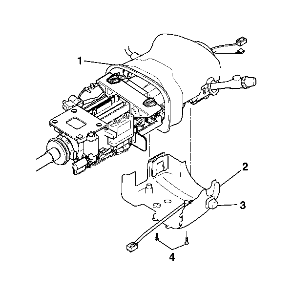
- Remove the retaining screws (4) from the lower steering column trim cover.
- Disconnect the closeout trim cover from the lower trim cover.
- Disconnect the electrical connector for the power tilt and telescopic switch.
- Remove the electrical connector for the telescopic switch from the lower trim cover.
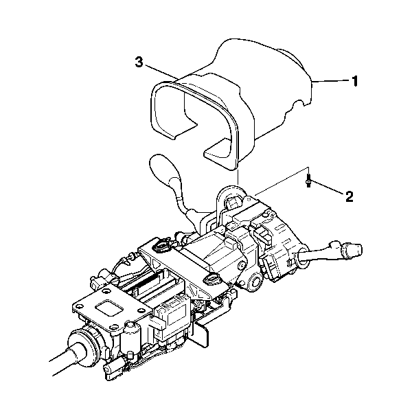
- Remove the retaining screw (2) from the upper steering column trim cover (1).
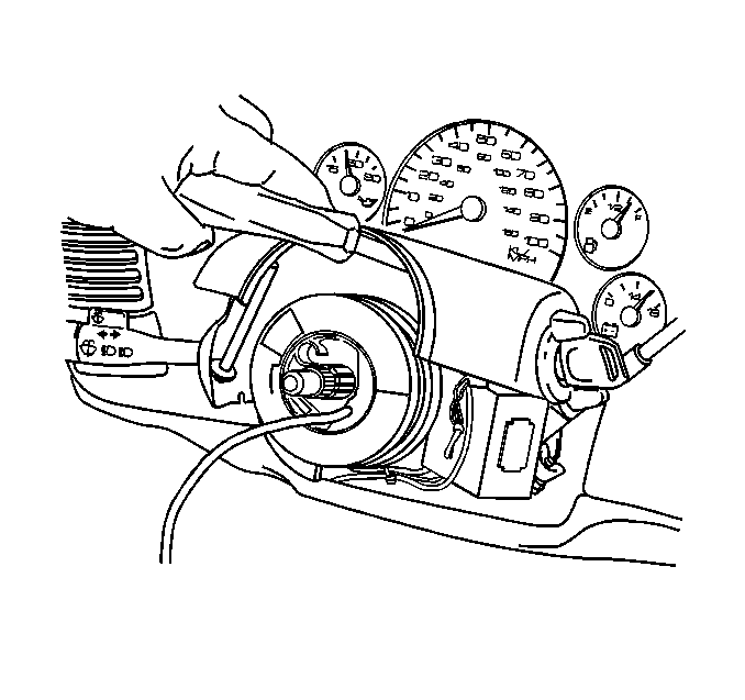
- Lift the upper trim cover to gain access to the lock cylinder access hole.
- Using a bent tip awl, insert the tip into the access hole.
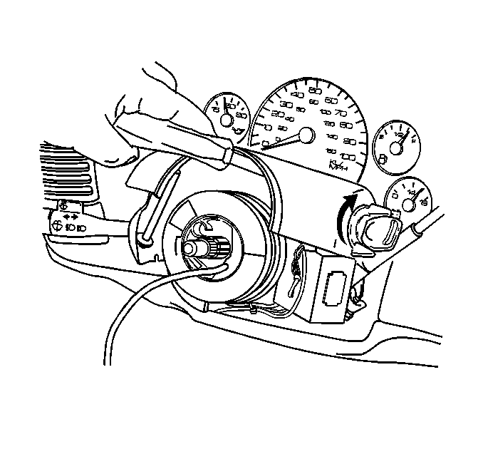
- Turn the ignition lock cylinder to the START position.
- Using the bent tip awl push down on the ignition lock cylinder retaining pin.
- Release the ignition lock cylinder to the RUN position and remove the lock cylinder.
- Remove the upper trim cover.
- Remove the closeout trim cover from the upper trim cover.
Caution: Refer to SIR Caution in the Preface section.
Caution: Unless directed otherwise, the ignition and start switch must be in the OFF or LOCK position, and all electrical loads must be OFF before servicing any electrical component. Disconnect the negative battery cable to prevent an electrical spark should a tool or equipment come in contact with an exposed electrical terminal. Failure to follow these precautions may result in personal injury and/or damage to the vehicle or its components.
Installation Procedure
- Install the upper steering column trim cover (1) to the closeout trim cover.
- Install the upper trim cover (1) to the steering column.
- Install the retaining screw to the upper trim cover.
- Install the Ignition lock cylinder.
- Install the lower steering column trim cover (2) and ensure that the tabs on the lower trim cover engage with the tabs on the upper trim cover (1). Snap the covers together.
- Connect the lower trim cover to the closeout trim cover.
- Install the retaining screws to the lower trim cover.
- Install the gap hider. Refer to Instrument Cluster Replacement in Instrument Panel, Gages, and Console.
- Install the knee bolster. Refer to Driver Knee Bolster Replacement in Instrument Panel, Gages, and Console.
- Install the steering wheel. Refer to Steering Wheel Replacement .
- Connect the battery negative cable. Refer to Battery Negative Cable Disconnection and Connection in Engine Electrical.
- Enable the SIR system. Refer to SIR Disabling and Enabling in SIR.

Notice: Refer to Fastener Notice in the Preface section.
Tighten
Tighten the screw to 1.5 N·m (13 lb in).

Tighten
Tighten the screws to 3 N·m (27 lb in).
Steering Column Trim Cover Replacement Manual Tilt
Removal Procedure
- Disable the SIR system. Refer to SIR Disabling and Enabling in SIR.
- Disconnect the battery negative cable. Refer to Battery Negative Cable Disconnection and Connection in Engine Electrical.
- Remove the steering wheel. Refer to Steering Wheel Replacement .
- Remove the knee bolster. Refer to Driver Knee Bolster Replacement in Instrument Panel, Gages, and Console.
- Remove the gap hider. Refer to Instrument Cluster Replacement in Instrument Panel, Gages, and Console.
- Put the steering column in the CENTER position.
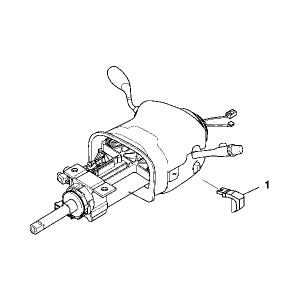
- Remove the tilt lever (1).
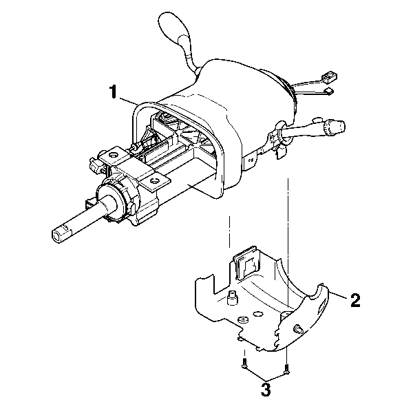
- Remove the retaining screws (3) from the lower steering column trim cover.
- Disconnect the closeout trim cover from the lower steering column trim cover.
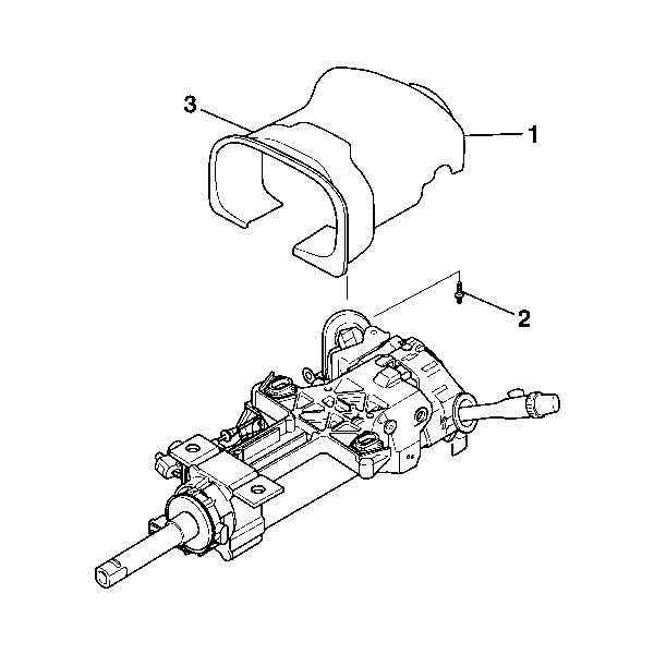
- Remove the retaining screw (2) from the upper steering column trim cover (1).
- Lift the upper trim cover to gain access to the lock cylinder access hole.
- Using a bent tip awl, insert the tip into the access hole in the ignition lock cylinder.
- Turn the ignition lock cylinder to the START position.
- Using the bent tip awl push down on the retaining pin of the ignition lock cylinder.
- Release the ignition lock cylinder to the RUN position and remove the lock cylinder.
- Remove the upper trim cover.
- Remove the closeout trim cover from the upper trim cover.
Caution: Refer to SIR Caution in the Preface section.
Caution: Unless directed otherwise, the ignition and start switch must be in the OFF or LOCK position, and all electrical loads must be OFF before servicing any electrical component. Disconnect the negative battery cable to prevent an electrical spark should a tool or equipment come in contact with an exposed electrical terminal. Failure to follow these precautions may result in personal injury and/or damage to the vehicle or its components.


Installation Procedure
- Install the upper steering column trim cover (1) to the closeout trim cover.
- Install the upper trim cover (1) to the steering column.
- Install the retaining screw (2) to the upper steering column trim cover.
- Install the Ignition lock cylinder.
- Install the lower trim cover (2) and ensure that the tabs engage with the tabs on the upper trim cover (1). Snap the tabs together.
- Connect the lower steering column trim cover to the closeout trim cover.
- Install the retaining screws (3) to the lower steering column trim cover.
- Install the tilt lever (1).
- Install the gap hider. Refer to Instrument Cluster Replacement in Instrument Panel, Gages, and Console.
- Install the knee bolster. Refer to Driver Knee Bolster Replacement in Instrument Panel, Gages, and Console.
- Install the steering wheel. Refer to Steering Wheel Replacement .
- Connect the battery negative cable. Refer to Battery Negative Cable Disconnection and Connection in Engine Electrical.
- Enable the SIR system. Refer to SIR Disabling and Enabling in SIR.

Notice: Refer to Fastener Notice in the Preface section.
Tighten
Tighten the screw to 1.5 N·m (13 lb in).

Tighten
Tighten the screws to 3 N·m (27 lb in).

