Info - 4L60-E/4L65-E/4L70-E Automatic Transmission Product Update

| Subject: | 4L60-E / 4L65-E / 4L70-E Automatic Transmission Product Update |
| Models: | 2005 GM Passenger Cars and Light Duty Trucks |
| 2005 HUMMER H2 |
| 2005 Saab 9-7X |
| with 4L60-E, 4L65-E or 4L70-E Automatic Transmission (RPOs M30, M33, M32, M70) |
This bulletin is being revised to reflect recent pump cover changes. Please discard Corporate Bulletin Number 05-07-30-028 (Section 07 -- Transmission/Transaxle).
This purpose of this bulletin is to update technicians to changes in the 4L60-E, 4L65-E and 4L70-E automatic transmissions.
Pump Cover Changes
TCC Valve and Spring Design Change
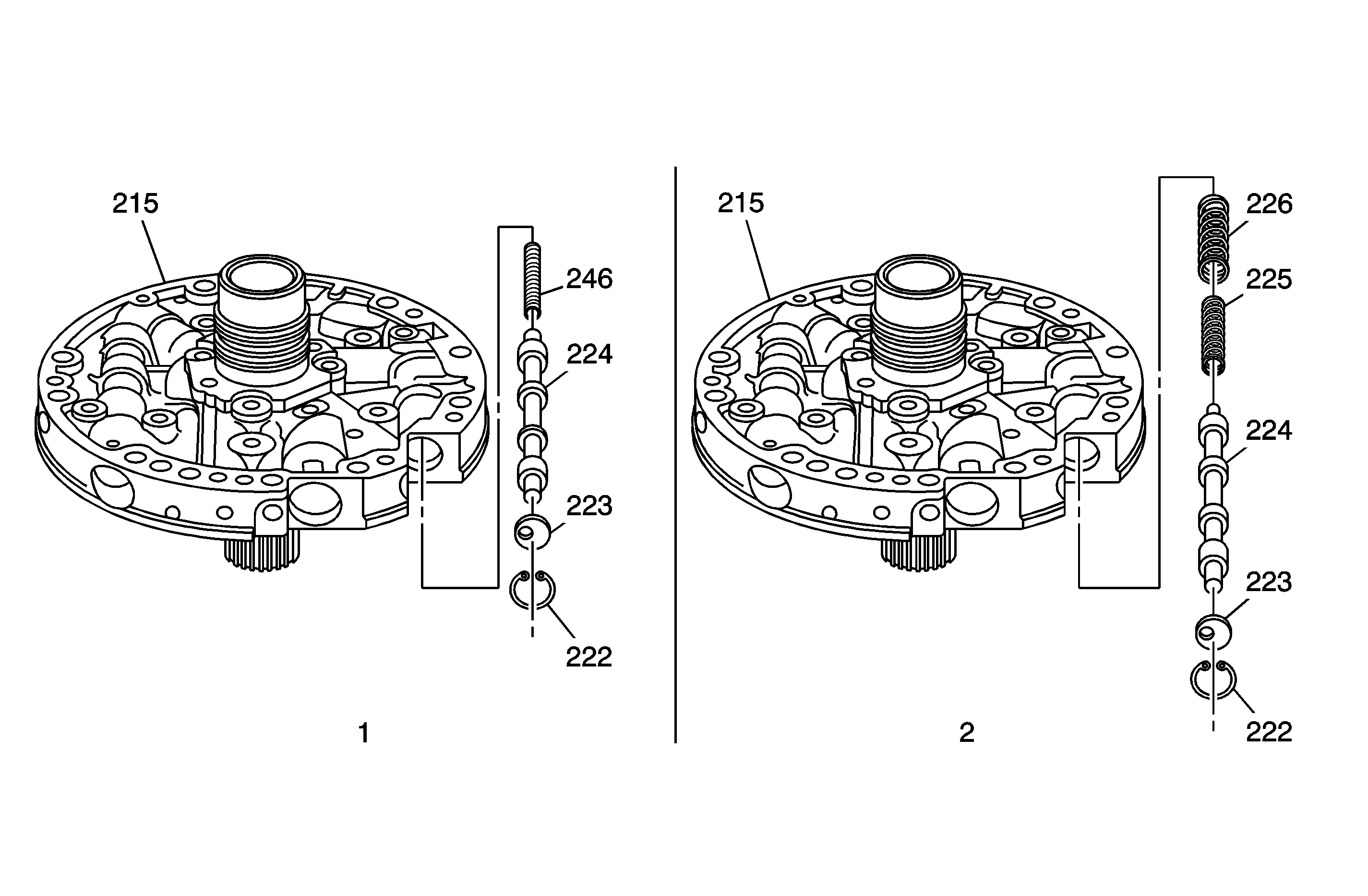
Effective February 1, 2005, the pump cover (215) now uses a new torque converter clutch (TCC) valve (224) with a single torque converter clutch (TCC) valve outer spring (246) (View 1). The single spring replaces the double spring design (View 2).
The new TCC valve (224) (View 1), incorporates a spring pocket to prevent incorrect installation. The valve will only allow the spring to be installed in the pocket-end of the valve.
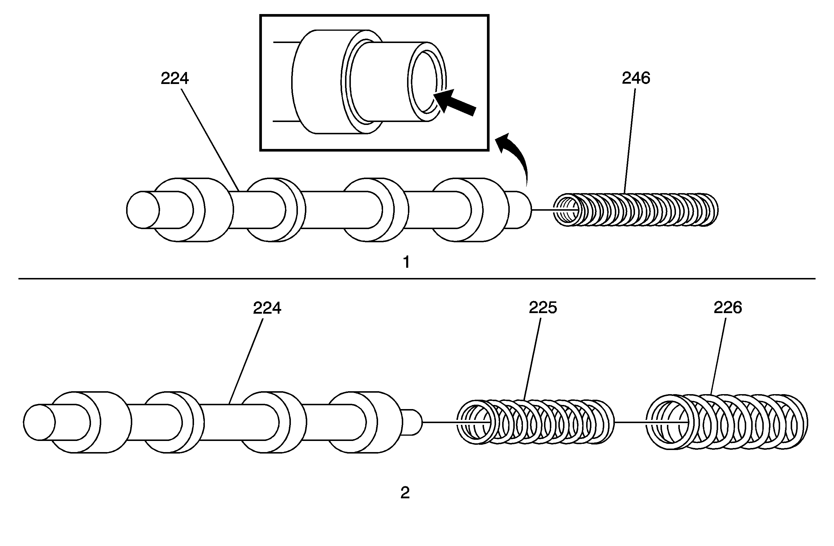
Components of the two designs may not be intermixed, although the single spring and valve design can be substituted for the early valve and two-spring design (View 2). This change simplifies the assembly process and eliminates the possibility of the springs becoming bound or bent in the valve bore as well as reduces material cost.
Reverse Boost Valve and Bushing Design Change
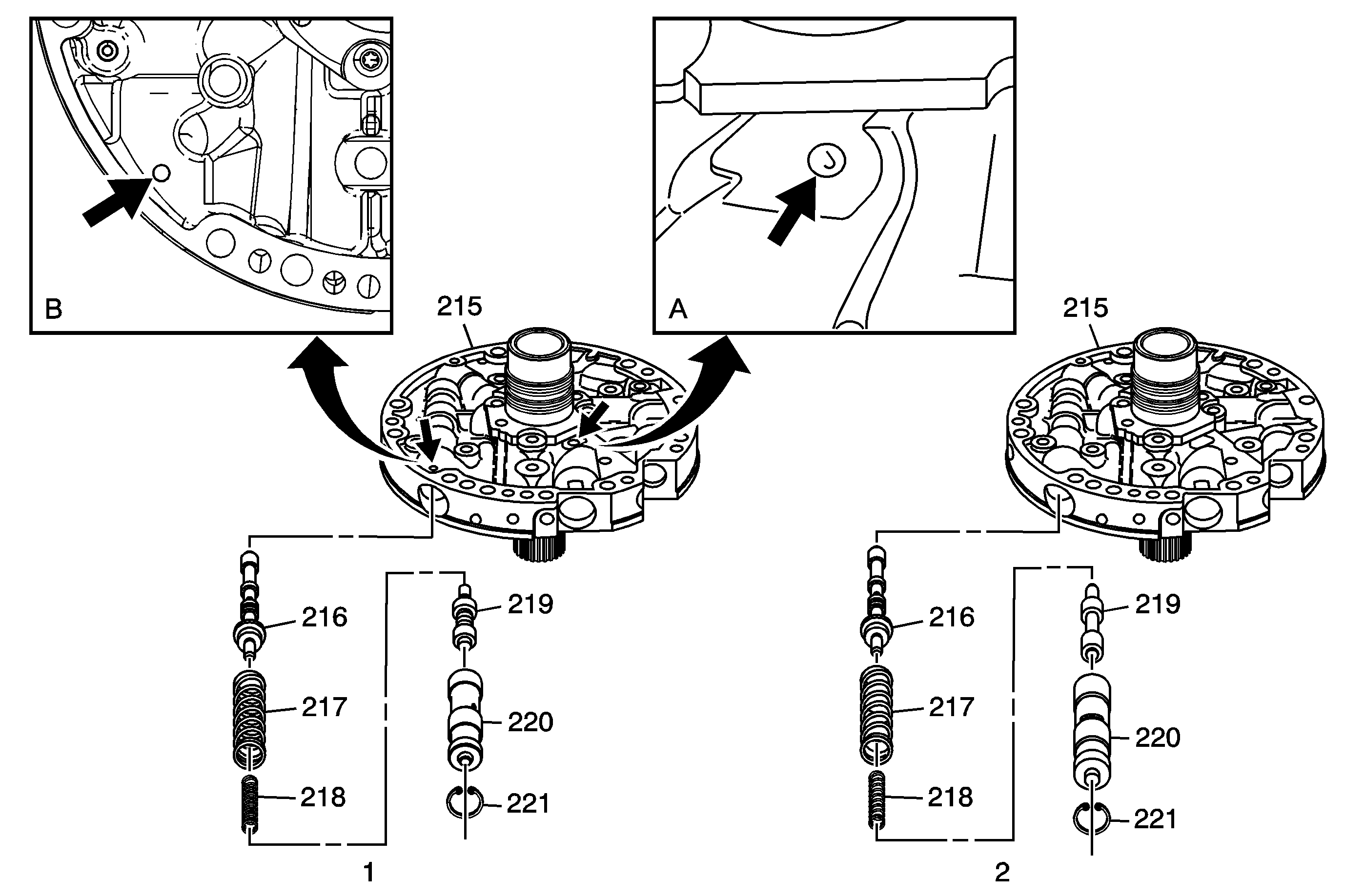
Effective March 7, 2005, the pump cover (215) now uses a more compact reverse boost valve (219) and reverse boost bushing (220) (View 1). This design change is necessary in order to create an area for the new input speed sensor (ISS) assembly which will be first introduced in some 2006 M30 and M70 transmission models.
The compact design works the same as the previous design but the two designs cannot be interchanged. This is because the snap ring groove location has changed, making the pump cover bore length 2.7 mm (0.106 in) smaller.
To identify this pump cover, look for a stamped circle surrounding a letter on the machined surface below the stator shaft (View 1A), or a dimple or slight hole in-line with the boost valve bore opening (View 1B). The pump cover with the stamped circle is manufactured at the Toledo transmission plant. Pump covers with the dimple/hole are manufactured at the Romulus, Michigan or Ramos, Mexico transmission plant.
Pump Cover Assemblies
The following text and illustrations will help you identify recent pump cover changes. The information begins with pump cover 1, before the addition of the input speed sensor (ISS), and continues with the consecutive changes (pump covers 2 and 3) that allowed manufacturing to gradually incorporate the ISS into pump cover 4. One important fact is that early pump covers cannot be used with ISS-equipped transmissions. Upon review of the information, note the identification characteristic of each pump cover.
Pump Cover 1 - Initially Manufactured in 1998 : This design uses two similar reverse boost valves and bushings. Rings and grooves identify the valve and bushing type. There are two types of boost valves, standard and high performance, each with a corresponding bushing. The pressure regulator valve (216), the pressure regulator valve spring (217) and the pressure regulator isolator spring (218) remain unchanged.
Pump Cover 2 (Pre-input speed sensor (ISS) models) - Manufactured 3/6/2005 to 7/16/2005: This pump cover is modified to accept a compact reverse boost valve (219) and reverse boost bushing (220). The design change was necessary in order to prepare for the new input speed sensor (ISS) assembly that will be packaged into the pump cover. This particular change created additional space below the valve area, so that the new pump cover 3 would have the necessary room for the input speed sensor (ISS) connector. This compact design relocates the snap ring groove in the valve bore as explained above. This design uses a smaller reverse boost valve and bushing and can be identified by the ring and groove markings. There are two types of boost valves, standard and high performance, with a corresponding bushing. This cover may also be identified by the manufacturing features noted in the illustration.
Pump Cover 3 (Pre-ISS models): Late in the 2005 model year, the pump cover casting was modified in order to incorporate the input speed sensor (ISS) connector. This modification will remove metal directly below the pressure regulator valve and reverse boost valve bore and extend a cast wall inward. This wall establishes the mounting point for the ISS connector. The casting change will also create a mounting surface for the ISS assembly. The ISS location places the assembly in position to target the rotor teeth on the input turbine shaft. Because of this mounting location, the internal TCC release oil pump passage had to be modified. This affected the stator shaft and the stator shaft bushing. A new stator shaft and bushing are used to relocates the oil passages in the pump cover. The turbine shaft for this pump has relocated oil seal ring grooves that correlate with the new stator shaft and stator shaft bushing. The turbine shaft oil grooves were moved to create an area to manufacture the ISS rotor teeth. Turbine shafts with relocated oil grooves can be identified as shown in the illustration as well as the noticeable large land area just ahead of the first oil seal ring groove. Some pre-ISS models may have ISS rotor teeth on the turbine shaft and some may not. This was a manufacturing option. Either way, with or without ISS rotor teeth, these turbine shafts cannot be installed into early design pump covers due to the relocation of the oil pump TCC oil circuits and the turbine shaft oil seal ring groove locations.
Pump Cover 4 (ISS & Non-ISS Models) - Late in the 2005 and early in the 2006 model year, non-ISS models may not have the ISS mounting holes machined into the cover. This will leave smooth un-machined surface, without the ISS mounting holes. Later, as more ISS models are introduced, the machining of the ISS mounting area will take place. For these non-ISS models, an ISS hole plug (248) will be used in place of the ISS assembly.
This pump cover also uses the compact reverse boost valve (219) and reverse boost bushing (220).
Important Part Ordering Information
It is very important when ordering repair parts that you order by the transmission model. Check the parts you receive and match them to the transmission model and pump cover design.
Because the input speed sensor (ISS) was phased into production, certain design levels had to be followed. This one detail is the reason for careful parts identification, in particular, the matching of the oil pump assembly to the turbine shaft/input clutch housing assembly.
Example; pump assembly 1 could not be used in place of pump cover 3. This is because the turbine shaft oil grooves would not align with the stator shaft bushing oil holes in the pump. This would not allow the oil to be delivered correctly. Incorrect transmission operation and damage would result.
Important: The 4L60-E, 4L65-E, and 4L70-E automatic transmissions will not function properly if the wrong combination of Reverse Boost Valves, Reverse Boost Valve Bushings, Pump Covers, and Input Housing assemblies are installed or intermixed.
Important: The 4L60-E, 4L65-E, and 4L70-E automatic transmissions will not function properly if the turbine shaft/input housing assembly are not first identified, and matched with its corresponding oil pump. Pump Covers and Input Housing assemblies should never be intermixed between different transmission models.
Pump Cover 1
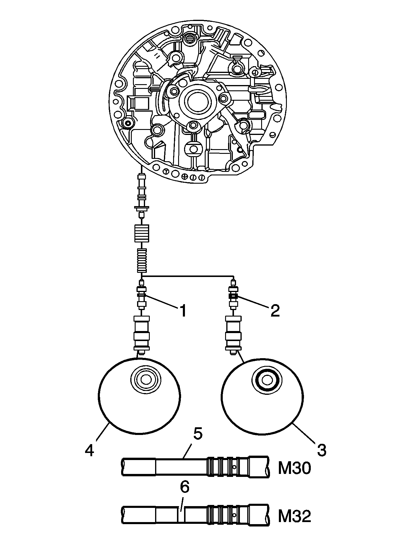
Pump Cover 1 | |||||
|---|---|---|---|---|---|
ID Feature: None | |||||
Reverse Boost Valve:
Use only with pump cover 1. | |||||
Reverse Boost Bushing:
Use only with pump cover 1. | |||||
Std. Turbine Shaft: No ID band (5) Use with pump cover 1. May be used with pump cover 2, never in 3 or 4. | |||||
HD Turbine Shaft: One ID band (6) Use only with pump cover 1 or 2. | |||||
Pump Cover 2
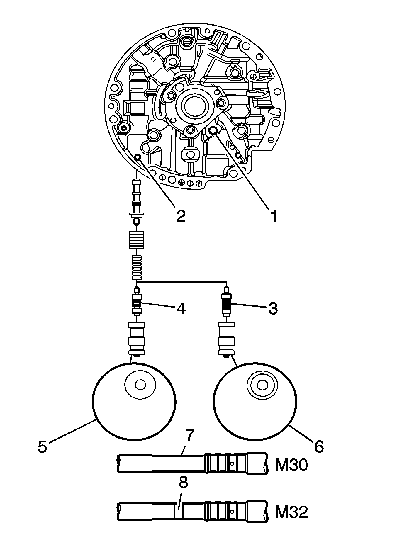
Pump Cover 2 | |||||
|---|---|---|---|---|---|
ID Feature: Cover dimple/hole and reverse boost valve snap ring location.
| |||||
Reverse Boost Valve:
Can be used in pump cover 2, 3 or 4 - not in pump cover 1. | |||||
Reverse Boost Bushing:
Can be used in pump cover 2, 3 or 4 - not in pump cover 1. | |||||
Std. Turbine Shaft: No ID band (7). Use with pump cover 2. May be used with pump cover 1 - never in 3 or 4. | |||||
HD Turbine Shaft: One ID band (8) Use with pump cover 2. May be used with pump cover 1 - never in 3 or 4. | |||||
Pump Cover 3
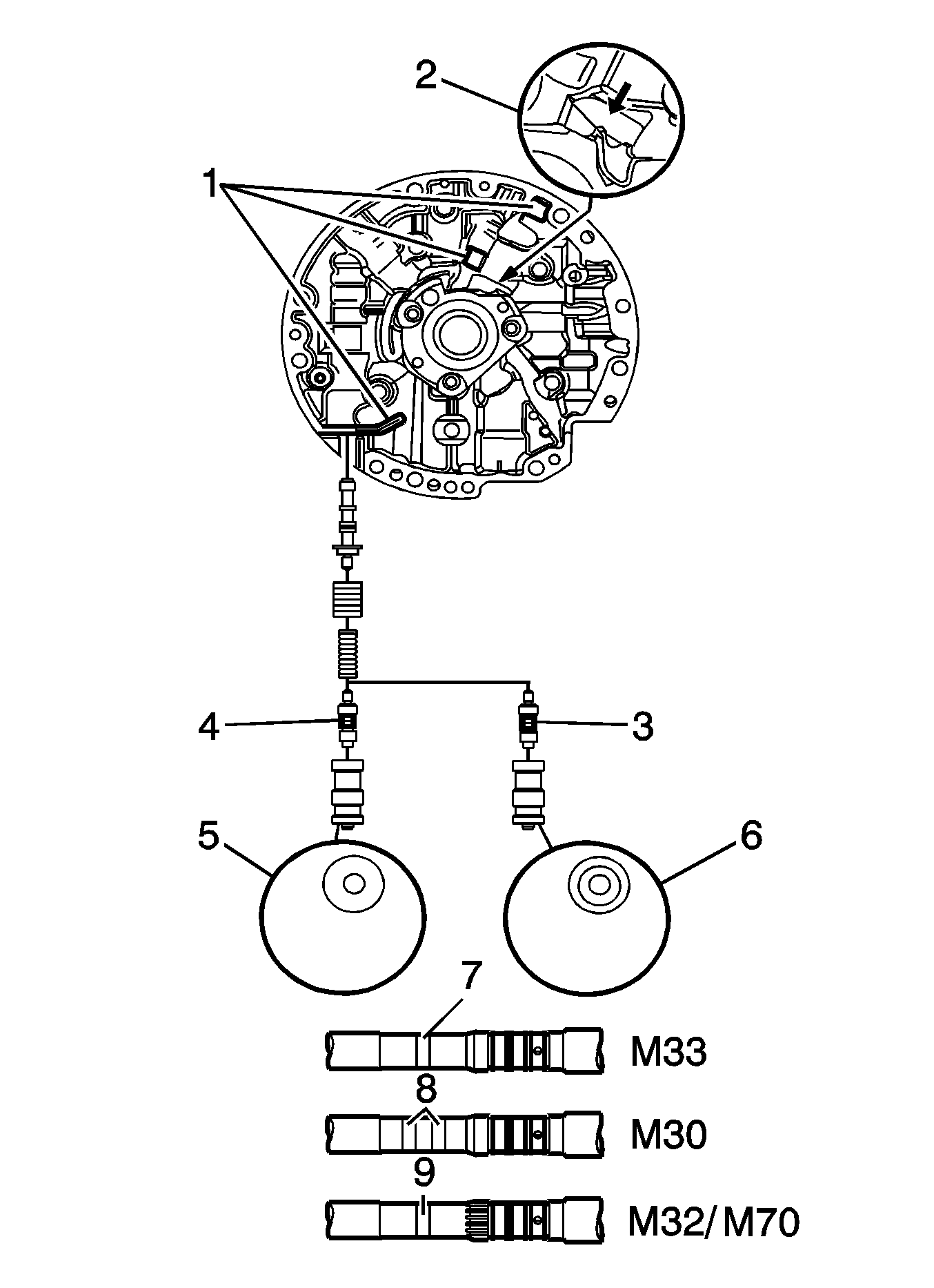
Pump Cover 3 | |||||
|---|---|---|---|---|---|
ID Feature: Cast wall improvements, machined ISS area.
| |||||
Reverse Boost Valve:
Can be used in pump cover 2, 3 or 4 - NOT in pump 1. | |||||
Reverse Boost Bushing:
Can be used in pump cover 2, 3 or 4 - not in pump 1. | |||||
Std. Turbine Shaft: Two ID bands (8). Use with pump cover 3. May be used with pump cover 4 - never in 1 or 2. | |||||
HD & PHT Turbine Shaft:
Use only with pump cover 3. May be used with pump cover 3 or 4 - never in 1 or 2. | |||||
Pump Cover 4
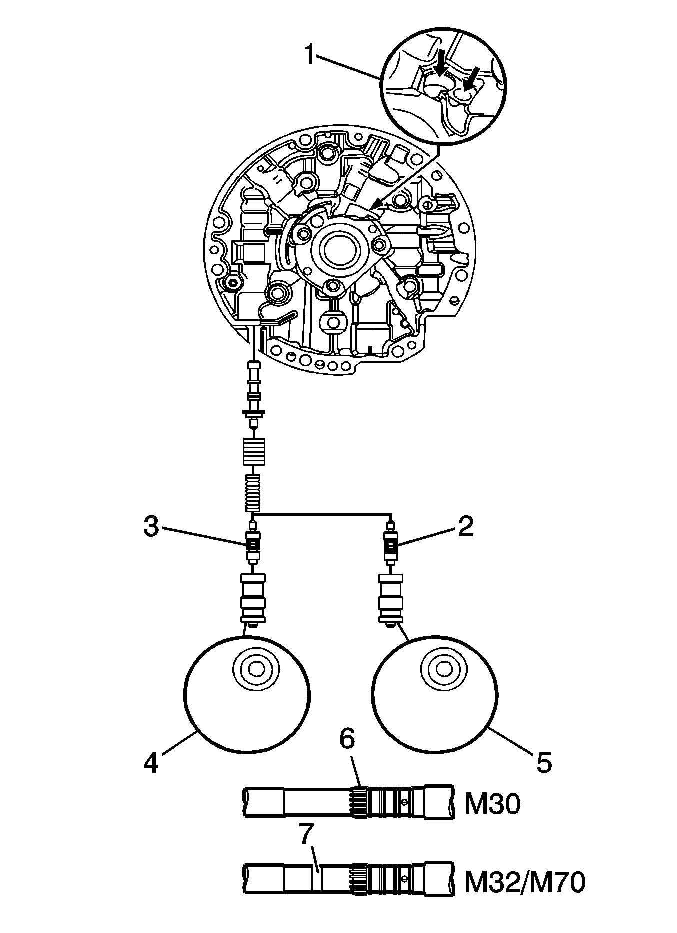
Pump Cover 4 | |||||
|---|---|---|---|---|---|
ID Feature: Machine surface and drilled ISS holes. Holes Drilled (1) | |||||
Reverse Boost Valve:
Can be used in pump cover 2, 3 or 4 - NOT in pump 1. | |||||
Reverse Boost Bushing:
Can be used in pump cover 2, 3 or 4 - not in pump 1. | |||||
Std. Turbine Shaft: ISS rotor teeth (6) Use with pump cover 4. May be used with pump cover 3- never in 1 or 2. | |||||
HD Turbine Shaft: ISS rotor teeth and one ID band (7) Use with pump cover 4. May be used with pump cover 3 - never in 1 or 2. | |||||
Input Speed Sensor (ISS) Assembly
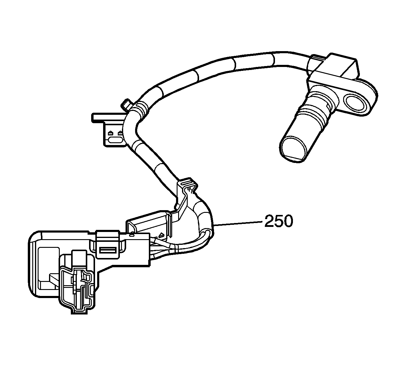
To improve product quality, reduce warranty cost and be common with other transmissions, an input speed senor (ISS) assembly (250) has been designed into the oil pump cover. This new component makes the 4L60-E common with other Hydra-Matic™ electronic transmissions by enabling algorithm (computer instructions) such as shift energy and abuse torque management, as well as improved transmission diagnostic capabilities, designed to reduce the K9995 labor operation (cannot duplicate). The ISS assembly (250) is a three-wire hall-effect sensor that is mounted internally to the transmission oil pump assembly. The ISS utilizes the rotor teeth located on the turbine shaft to generate a voltage signal of varying frequency that corresponds to the rotational speed of the turbine shaft. The ISS signal is an input to the transmission control module (TCM) and is used to determine line pressure, transmission shift patterns, torque converter clutch (TCC) slip speed and gear ratio.
Input Speed Sensor (ISS) Service Considerations
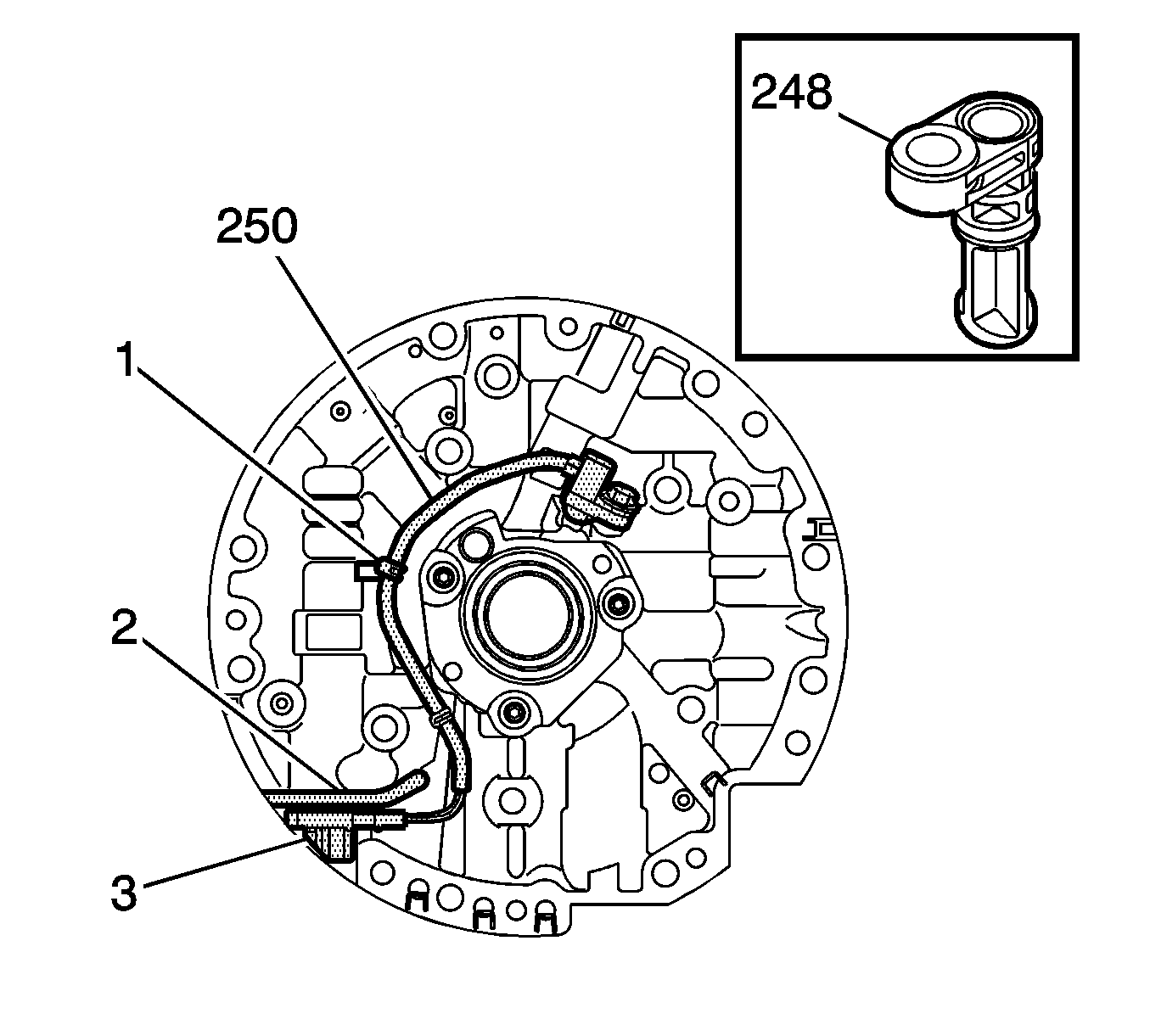
Because the ISS connector (3) is located below the pressure regulator (PR) valve, it blocks the entrance to the PR valve line up. This now prevents the ability to remove the PR valve while the transmission is in the vehicle. This procedure can only be completed with the pump removed from ISS-equipped transmission.
The ISS assembly wiring is attached to the pump cover with two steel brackets (1 and 2) which are pushed in place onto the pump casting. The bracket locations are important in order to ensure the harness lies flat against the pump cover, preventing contact with the rotating reverse input clutch housing. Avoid distorting the ISS wiring brackets when prying them from the pump cover. If the brackets don't hold tightly to the pump surface, the ISS assembly must be replaced.
For transmission models that do not use an input speed sensor, an ISS hole plug assembly (248) is used to block the machined bore. The ISS plug incorporates the same O-ring seal as the ISS assembly, and if omitted or damaged during repair, it could produce objectionable TCC operation. To aid the installation of the ISS into the pump cover, the O-ring should be lubricated with transmission oil.
Transmission Internal Wiring Harness
The transmission internal wiring harness contains additional circuits for ISS-equipped transmissions. The ISS circuits occupy pin positions E, K, and V in the 20-way pass-thru connector. An ISS harness can be identified by the black 20-way pass-thru connector, where a non-ISS harness has a light grey connector.
Transmission Pass-thru Connector
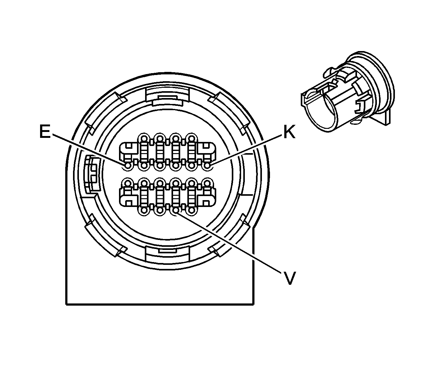
Pin | Wire Color | Circuit No. | Function |
|---|---|---|---|
E* | RD | 839 | Ignition 1 Voltage |
K | BK | 1230 | ISS Signal |
V | D-GN | 1231 | Low Reference |
* Existing circuit -- ISS power is spliced into this circuit. | |||
Transmission Harness ISS Connector
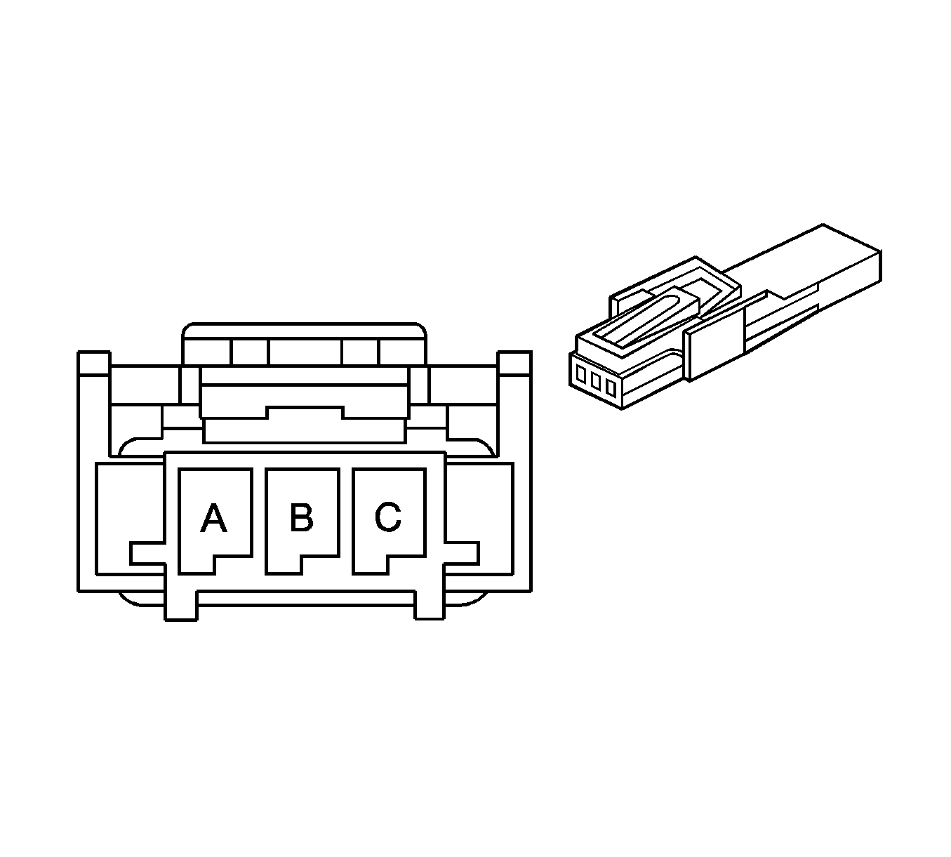
Pin | Wire Color | Circuit No. | Function |
|---|---|---|---|
A | BK | 1230 | ISS Signal |
B | RD | 839 | Ignition Voltage |
C | D-GN | 1231 | Low Reference |
ISS Assembly Connector
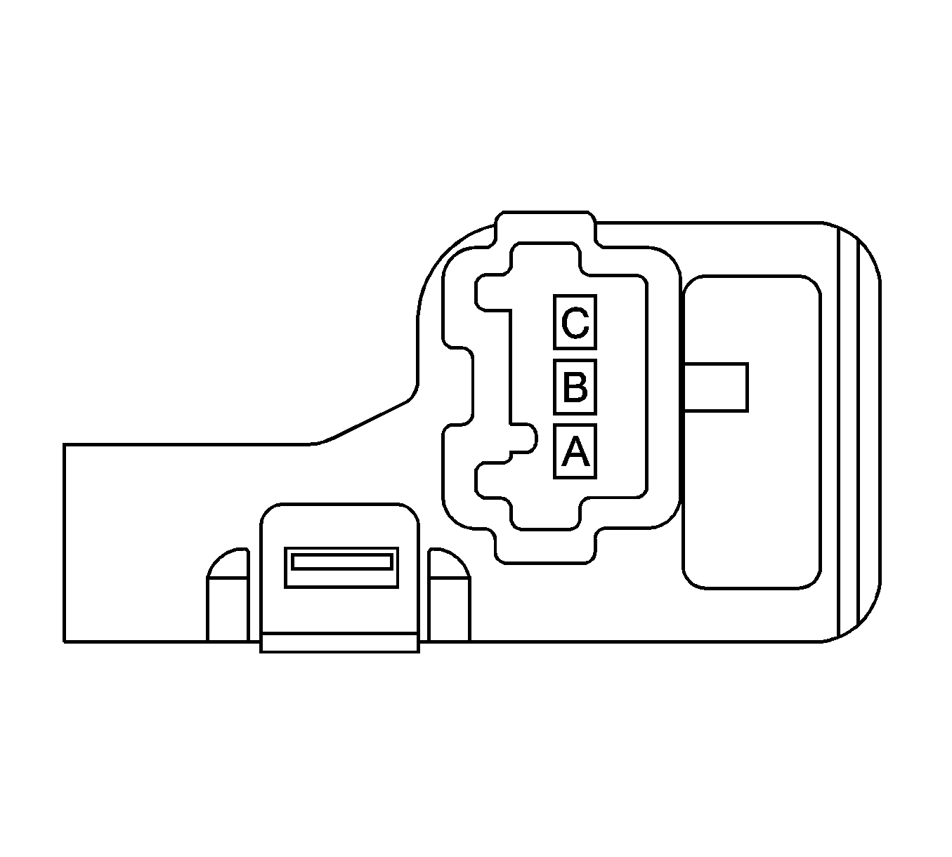
Pin | Wire Color | Circuit No. | Function |
|---|---|---|---|
A | RD | 1230 | ISS Signal |
B | WH | 839 | Ignition Voltage |
C | BK | 1231 | Low Reference |
Wiring Harness Cover and Channel
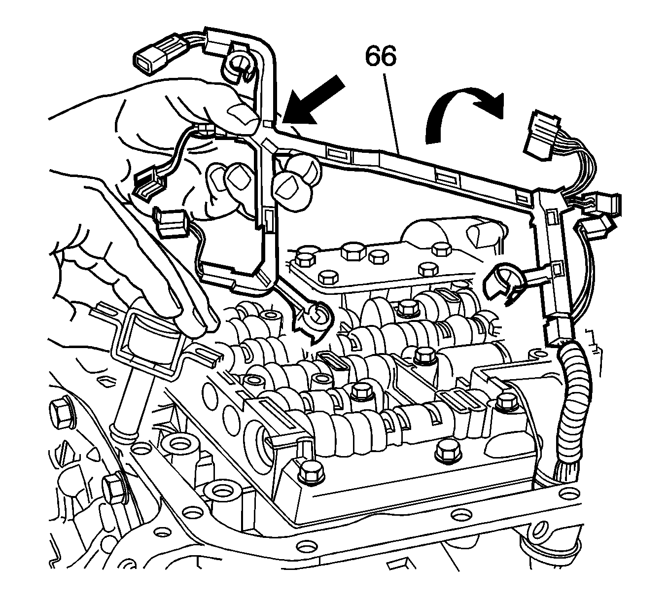
For transmission assembly plant purposes, the wiring harness cover (66) and channel which protects the internal wiring and attaches to the valve body, now contains a hinged area that allows the ISS branch to be folded over. After repeated folding, this hinged area could break. This condition does not affect the function of the harness and should not be a reason for replacement.
Input Speed Sensor (ISS) Diagnostics
ISS DTCs
There are two powertrain diagnostic trouble codes (DTCs) to support the ISS diagnosis. They are P0716 and P0717. These two codes are typical of ISS-equipped transmissions in which the DTC will detect a component performance breakdown or an electrical failure.
DTC P0716, Input Speed Sensor Performance, is designed to detect an unrealistic large change in the ISS speed (rpm). The PCM or TCM will compare the transmission input and output speed in order to determine a system problem.
DTC P0717, Input Speed Sensor Circuit Low Voltage, is designed to detect a low signal voltage from the ISS. If the PCM or TCM determines that the input speed is less than 100 rpm with the engine running, DTC P0717 will set.
Both DTC P0716 and P0717 are type B diagnostics which will illuminate the malfunction indicator light (MIL) upon completion of two consecutive trips with the failure present. Once the DTC sets, it will force a default action designed to protect the transmission.
ISS Testing
Because the ISS assembly is internal to the transmission, it is important that the ISS be thoroughly evaluated before removing it. Common problems such as poor terminal connection, worn wiring, or opens and shorts all need to be considered before transmission removal. The input speed sensor may be tested several ways, by substituting the ISS with a signal generator, common test light and circuit resistance. Due to the ISS circuitry design with its internal IC chip, it is not beneficial to measure the internal resistance. The scan tool is a useful tool to verify the component operation by doing rpm comparison readings.
For more troubleshooting information, refer to Symptom Diagnosis in the SI system.
ISS Models
| • | 4L60-E (M30) 2006 Models with the input speed sensor: SJD & KLD |
| • | 4L70-E (M70) 2006 Models with the input speed sensor: SKD & TKD |
ISS Warranty Information (Excluding Saab)
The labor operation number for the ISS replacement is K6311.
ISS Warranty Information (Saab Only)
The labor operation number for the ISS replacement is K6311.
Labor Operation | Description | Failed Object | Fault/Reason Code | Location Code | Warranty Type | Repair/Action Code | Labor Time |
|---|---|---|---|---|---|---|---|
4413004 | R&R Trans Oil Pump Eng Code S | 44130 | 67 | 0 | 01 | 01 | Use Published Labor Operation Time - Review STM for Associated Labor Operations |
4413005 | R&R Trans Oil Pump Eng Code P |
Additional ISS Information
Refer to SI for all ISS repair, diagnosis or description information.
