CUSTOM CRUISE III DIAGNOSIS/ SERVICE MANUAL

The Custom Cruise III cruise control system has been available as optional equipment for Cimarron since the 1984 model year and will now also become available as optional equipment on the 1986 Fleetwood Brougham. In addition, the 1986 Eldorado and Seville will use the same type servo assembly in BCM controlled cruise control systems as is used in the Custom Cruise III system.
The attached diagnosis manual, developed by AC Spark Plug, is being sent to all the Business Management Dealers to aid in the diagnosis of the Custom Cruise III system. While the diagnostics are not totally applicable to the 1986 Eldorado and Seville cruise systems the servo checkout procedure in this manual is valid for the servo assemblies used on the Eldorado and Seville.
1984-85 AC (K-34) Custom Cruise III Systems Service Manual
Foreword
AC Spark Plug Division, General Motors Corporation has prepared this service manual to help answer questions about operation and service of the 1984-85 AC Custom Cruise III cruise control system. This system is offered in two versions. AC Custom Cruise III and AC Integrated Custom Cruise III. It is also referred to as Tri-mode, 3 Mode Cruise or the K-34 Cruise Option.
AC Custom Cruise III was introduced on 1983 Chevrolet and GMC Trucks. Most 1984 and 1985 applications, except full size Cadillac use the AC Custom III system. The integrated Custom Cruise III system is used on 1984 and 1985 Corvettes and the 1984 Pontiac Fiero "P" car. 1985 Fiero also uses Custom Cruise III.
Custom Cruise III has electronic circuitry incorporated in a controller which is located under the dash. The speed signal is derived from the Vehicle Speed Sensor (VSS) speedometer buffer amplifier or a permanent magnet (PM) generator. Integrated Custom Cruise III has the electronic circuitry incorporated in the instrument cluster. The speed signal is obtained from a VSS, vehicle speed sensor speedometer and/or a transmission driven permanent magnet (PM) generator.
Although the 1984-85 cruise function operates similarly in all applications, there are system design differences which are explained in this service manual.
This service manual is intenede to be a quick, easy-to-use reference for servicing the 1984-85 Custom Cruise III system. It has been organized into seven major sections.
1. How to use Custom Cruise III 2. Components in the system 3. How the system operates 4. Diagnostic procedures 5. Service aids 6. Connector repair 7. Diagnostic Charts
Important Safety Notice
To reduce the chance of personal injury and/or property damage the following instructions must be carefully observed.
Proper service and repair are important to the safety of the service technician and the safe, reliable operation of all motor vehicles. If part replacement is necessary the part must be replaced with one of the same part number or with an equivalent part. Do not use a replacement part of lesser quality.
The service procedures recommended and described in this service manual are effective methods of performing service and repair. Some of these procedures require the use of tools specially designed for the purpose.
Accordingly, anyone who intends to use a replacement part, service procedure or tool, which is not recommended by the vehicle manufactured, must first determine that neither his safety or safe operation of the vehicle will be jeopardized by the replacement part, service procedure or tool selected.
It is important to note that this manual contains various "cautions" and "notices" that must be carefully observed in order to reduce the risk of personal injury during service or repair, or the possibility that improper service or repair may damage the vehicle or render it unsafe. It is also important to understand that these "cautions" and "notices" are not exhaustive, because it is impossible to warn of all the possible hazardous consequnces that might result from failure to follow these instructions.
Table of Contents Page
1. How to Use Custom Cruise III 1-1 Introduction 1-1 Operation, 1984-1985 Vehicles 1-2 Mode Control, Turn Signal Lever "Tap-up", "Tap-down" Feature 1-2 Mode Control, 1984-85 Chevrolet Berlinetta 1-3 2. Components in the System 2-1 Component Functions 2-1 Mode Control Switches 2-1 VSS Buffer Amplifier 2-2 PM Generator Speed Sensor 2-2 Electronic Control Module 2-2 Combination Vacuum Release Valve/Converter Clutch Switch 2-3 Vacuum Release Valve 2-3 Combination Vacuum Release Switch 2-3 Electric Vacuum Release Valve 2-4 Combination Cruise/Stop Light Switch 2-4 Clutch Switch 2-4 Servo Unit 2-5 Vacuum Accumulator 2-6 Harness Adapter 2-6 3. How the System Operates 3-1 Electrical/Vacuum System Operation 3-1 System Configurations 3-2 Circuit Schematics 3-3 4. Diagnostic Procedures 4-1 Preliminary Inspection 4-1 Test Procedures 4-2 Cruise System Inoperative 4-2 Applicable to 1984-85 Corvette Only 4-5 Performance Symptoms and Correction, (All cruise systems) 4-7 Custom Cruise III "Quick Checker" 4-8 Quick Checker Test Procedure 4-9 5. Service Aids 5-1 AC Custom Cruise III System Quick Checker 5-1 Quick Checker Special Operating Notes 5-2 Quick Checker Test Procedures 5-2 6. Connector Repair 6-1 Module Connector 6-2 Servo Connector 6-2 7. Diagnostic Charts 7-1
I. How to Use Custom Cruise III
Introduction
AC Custom Cruise III is sometimes referred to as "3 mode" cruise.
1983 Custom Cruise III used on Chevrolet and GMC light trucks is covered in a separate manual (SMCM-1).
The 1984-85 AC Custom Cruise III system is an extension of the cruise control system that AC Spark Plug Division has designed and produced since the 1977 vehicle model year. The Custom Cruise III system has been adapted to accommodate the lower manifold vacuum levels of smaller, fuel efficient vehicles.
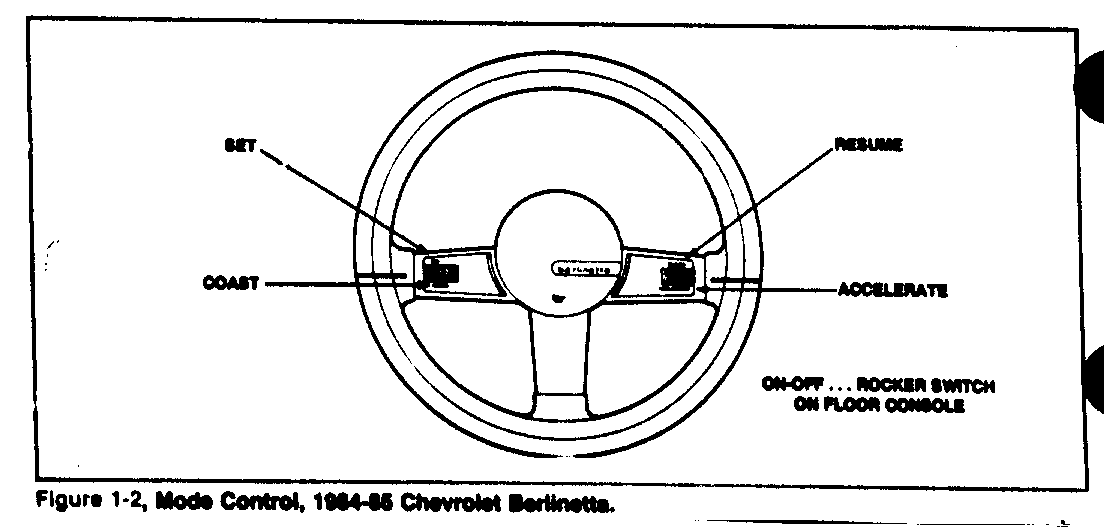
AC Custom Cruise III places at the driver's command the cruise control functions of cruise, coast, resume, "tap-up", "tap down" and accelerate. All functions, except for 1984-85 Chevrolet Berlinetta, are built-in the turn-signal lever (figure 1-1). The 1984-85 Chevrolet Berlinetta has cruise control functions built in the steering wheel "T" spoke ..... on ON-OFF switch is on the floor console (figure 1-2).
Operation, 1984-85 Vehicles
Mode Control on Turn Signal Lever
To engage the cruise mode, the slide switch (figure 1-1) must be removed from the "off" to the "on" position and the "set" push button (located in the end of the turn signal lever) must be depressed and released. The cruise set speed will be the vehicle speed at the particular time when the "set" push button is released. However, there is no cruise engagement below 25 mph. This is a low speed inhibit feature. The system may be disengaged by moving the mode control switch to the "off" position or by depressing the vehicle brake pedal or clutch pedal on manual transmission vehicles.
If the brake pedal is momentarily depressed to disengage cruise operation, the cruise set speed will be retained in the system "memory". To return the vehicle to the previously set cruise speed, Momentarily move the slider to the R/A (Resume/Accel) position.
DO NOT HOLD THE SLIDER IN THE R/A POSITION ... RELEASE IT IMMEDIATELY.
The vehicle will automatically accelerate to the previously set speed at a controlled rate. The controller "remembers" the last cruise speed unless "cleared" by an on-off of the ignition switch or the slider switch on the turn signal lever.
If the slider is held in the R/A position for more than one second, the system reverts to the ACCEL mode. When the slider is released, the speed the vehicle accelerated to becomes the new cruise speed. The vehicle operator may erroneously interpret this as an inoperative resume function.
If the slider is moved to the "R/A" position while in cruise and held, the vehicle will accelerate at a controlled rate until the slider is released. When the slider is released, the vehicle will continue to cruise at that speed. Reducing "set" speed can be accomplished by depressing and holding the SET/COAST button on the end of the turn signal lever until the vehicle "coasts down" to the desired speed. Vehicle speed at the moment of SET/COAST button release is the new set cruise speed. The accelerate function can be operated in either the cruise or non-cruise modes. Momentary slider switch movement to the R/A position after an off-on cycle will appear as a "set" cruise speed function.
Depressing the brake pedal while the Set/Coast or Rsume/Accel switches are engaged will disengage cruise. No switch action will be recognized until the Set/Coast, Resume/Accel switches and the brake pedal are all released.
The accelerator may be depressed at any time to override the cruise system. Release of the accelerator will return the vehicle to the previous set cruise speed.
"Tap-up", "Tap-down" Feature
On all 1984-85 applications, except 1984 Corvette and 1984 Pontiac Fiero "P" car, the Custom Cruise III system has a "tap-up", "tap-down" speed adjustment feature.
Tap-up results in a one-mile per hour speed increase by merely "tapping" the RESUME/ACCEL slider for less than one second. Tap-up may be repeated, but speed increase is limited to 10 miles per hour above vehicle speed.
Tap-down results in a one mile per hour speed decrease by merely "tapping" the SET/COAST button for less than 0.4 of a second. Each tap decreases speed and may be accumulated ... it is limited to a minimum cruising speed of 25 miles per hour.
1. How to Use Cutom Cruise III
Mode Control, 1984-85 Chevrolet Berlinetta
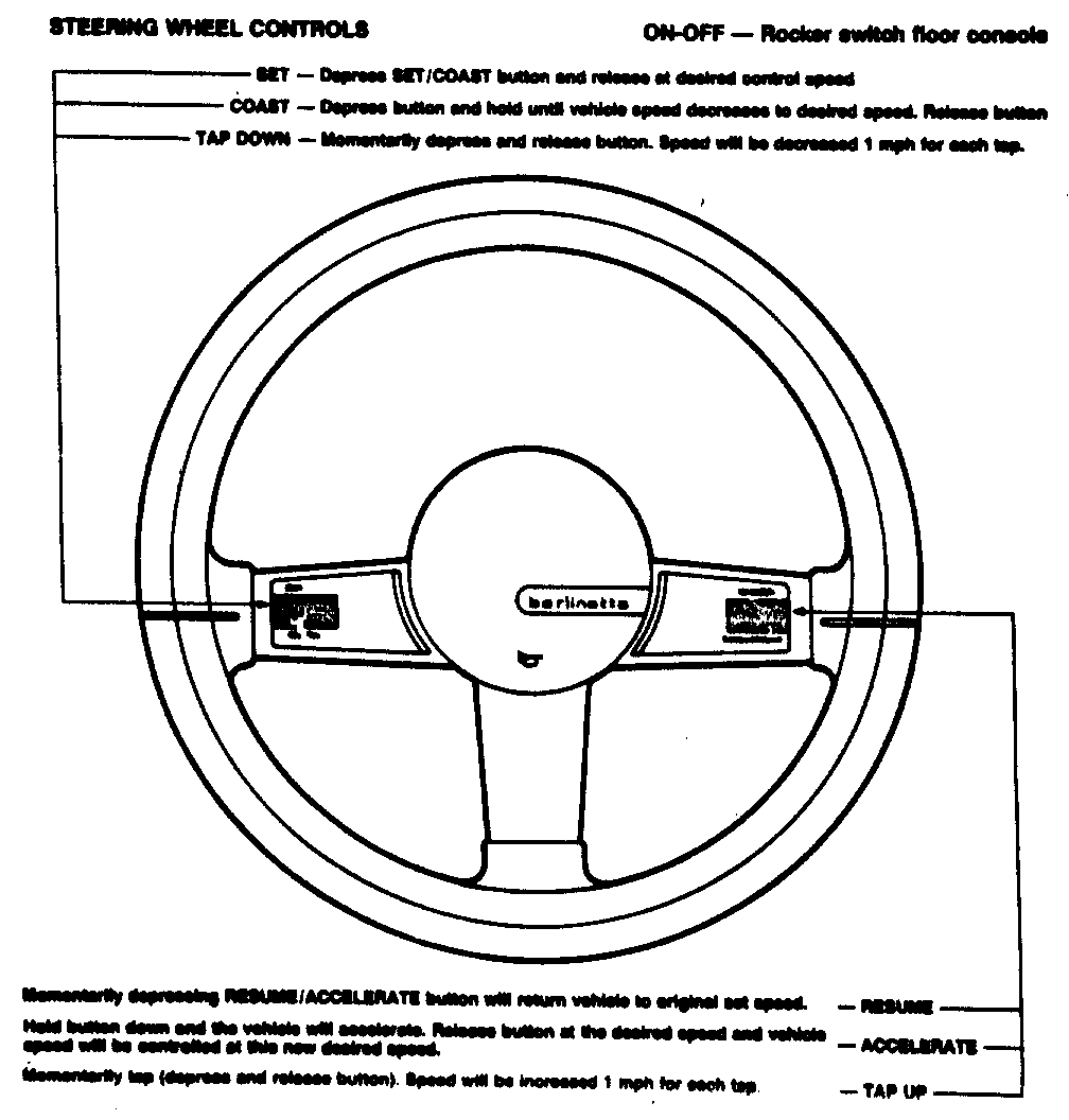
Figure 1-3 describes operation of the 1984-85 Berlinetta Electronic Cruise Control.
2. Components in the System
Component Functions
Mode Control Switches
Turn Signal Lever - The various operating modes of the Custom Cruise III system are controlled by means of the Mode Control Switches normally located on the turn signal lever (figure 1-1).
Steering Wheel - Custom Cruise III operating modes are controlled by Mode Control Switches built into the steering wheel on 1984-85 Chevrolet Berlinetta (figures 1-2 and 1-3)....ON-OFF is a rocker switch on the floor console.
VSS Buffer Amplifier
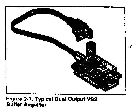
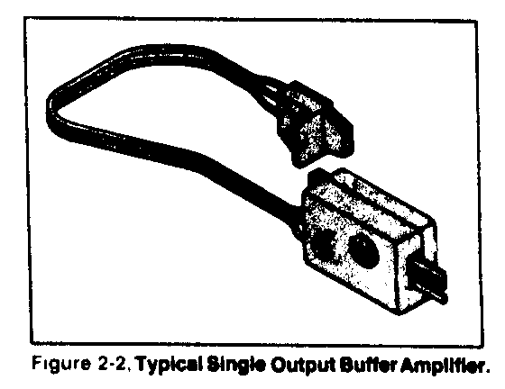
Vehicle speed information is "transmitted" to the Electronic Controller by a speed sensor, (a Vehicle Speed Sensor (VSS) Buffer Amplifier). See Figure 2-1 and 2-2. The output of the VSS Buffer Amplifier is a frequency proportional to vehicle speed. The signal is a square wave with a frequency of 0.556 Hz/MPH.
The four output buffer assembly used with the PM generator is shown in figure 3-6.
PM Generator Speed Sensor
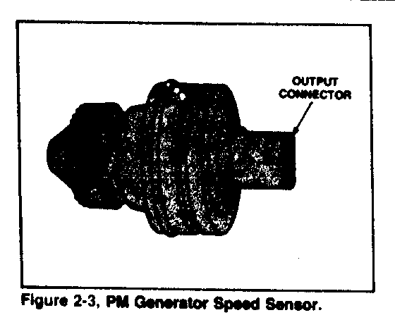
The PM generator speed sensor (figure 2-3) generates vehicle speed information in the form of a sine wave with a frequency of 1.112 Hz/MPH. On integrated Custom Cruise III, this signal is fed directly to the insrument cluster where it is converted to 0.556 Hz/MPH for cruise usage. On custom cruise III K34 option, it is fed to a buffer amplifier, where it is converted to 0.556 Hz/MPH for cruise usage.
Electronic Control Module
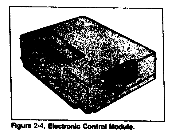
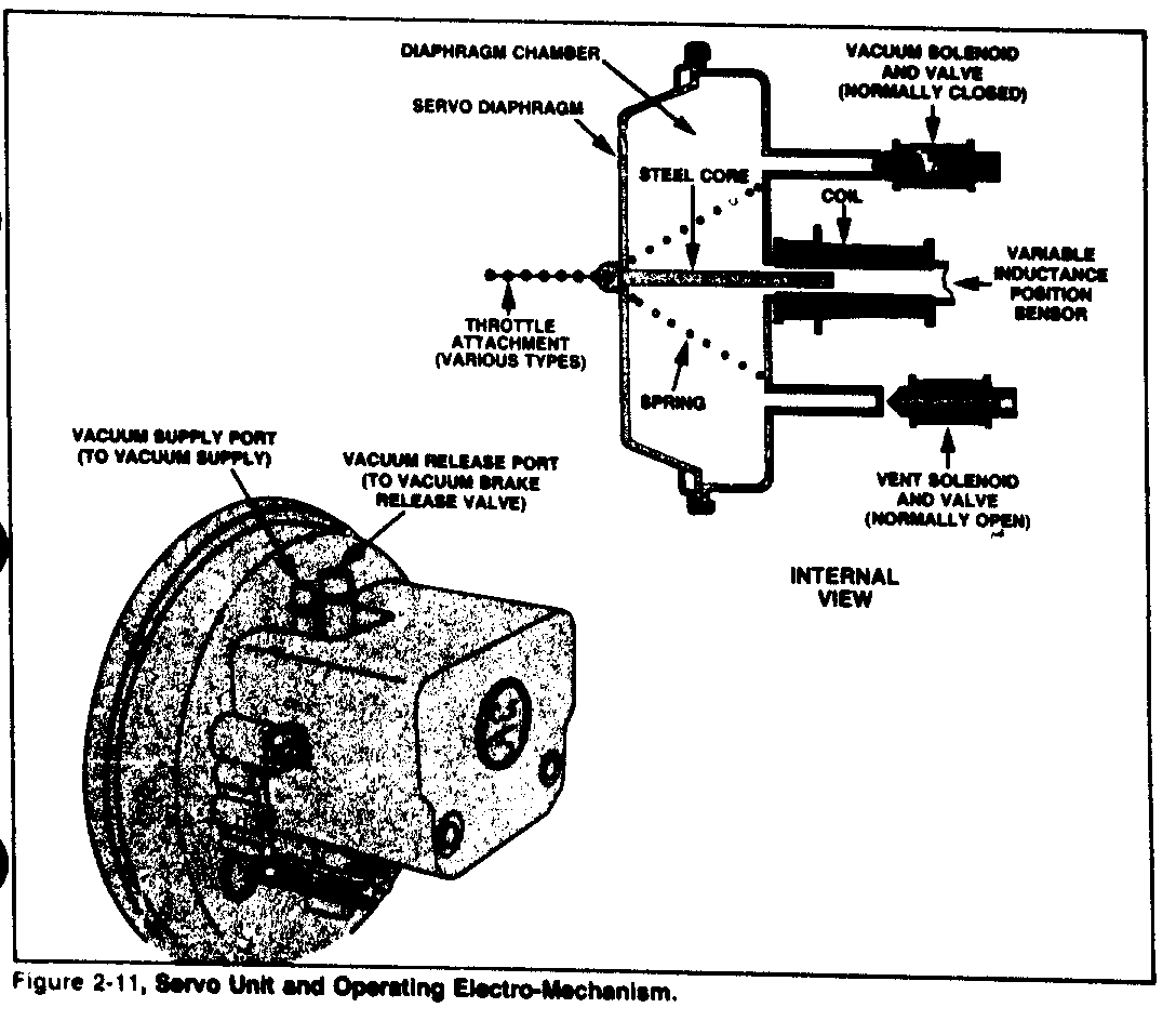
The Electronic Controller (figure 2-4) contains a digital integrated circuit and supporting analog circuits. The controller interprets the position of the servo unit, the position of the mode control switches and the output of the speed sensor. In response to these inputs, the controller electrically signals the opening or closing of the vent and vacuum solenoid valves in the servo unit (see figure 2-11).
In Custom Cruise III applications, the Electronic Control shown in figure 2-4 is usually mounted on some structural component under the dash. On integrated Custom Cruise III, introduced on 1984-85 Corvette, and 1984 Pontiac Fiero "P" car, the electronic circuitry is built in the instrument panel.
Combination Vacuum Release Valve Converter Clutch Switch
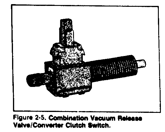
Vehicles equipped with a lock up torque converter (locking clutch) transmission use a Combination Vacuum Release Valve/Converter Clutch Switch (figure 2-5). The Vacuum Release Valve provides an additional vent for the servo unit to the atmosphere when the brake pedal is held in a depressed position. This "venting" action is spring actuated when the brake pedal is depressed and occurs withint he "free-travel" of the brake pedal arm. At the same time, the contacts in the Converter Clutch Switch open, which disengages the locking clutch mechanism in the transmission.
Vacuum Release Valve
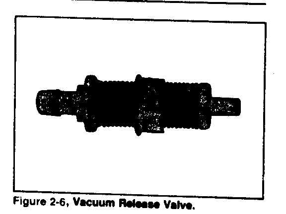
Vehicles without a lock up torque converter clutch transmission use a Vacuum Release Valve (figure 2-6). It provides an additional vent for the servo unit to the atmosphere when the brake pedal is held in a depressed position. This "venting" action is spring actuated when the brake pedal is depressed and occurs within the "free travel" of the brake pedal arm.
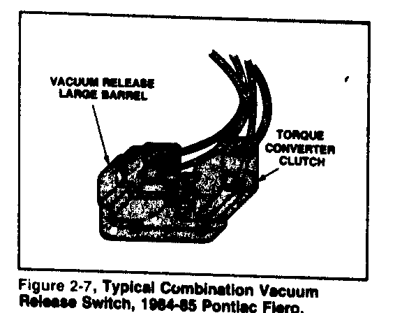
Combination Vacuum Release Switch
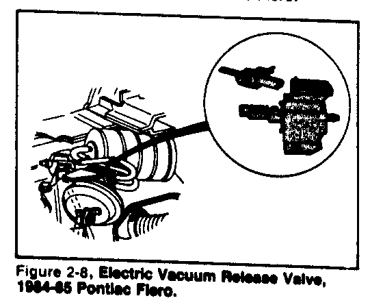
A combination vacuum release/torque converter clutch switch is located in the brake pedal bracket in the 1984-85 Pontiac Fiero "P" car (figure 2-7). When the brake is applied, the vacuum release switch deenergizes an electric vacuum release valve (see figure 2-8).
Figure 2-7 shows a brake pedal operated combination vacuum release/torque converter clutch switch used with automatic transmissions. On manual transmission cars, a similar switch arrangement is used on the brake and clutch pedal brackets. See Pontiac Service Manual.
Electric Vacuum Release Valve
The electric vacuum release valve is used in the 1984-85 Pontiac Fiero "P" car (figure 2-8). The solenoid in the valve is powered by vehicle ignition. When the brake pedal is not depressed, the solenoid is energized and the vacuum vlave is closed. When the brake is applied, the solenoid de-energizes and the vacuum valve and servo vent to the atmosphere ....the cruise function disengages.
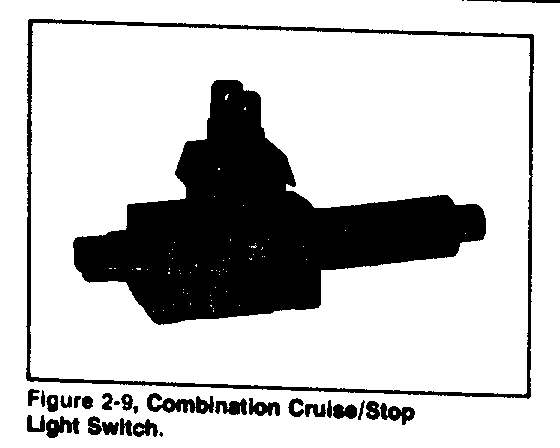
Combination Cruise/Stop Light Switch
The Combination Cruise/Stop Light Switch (figure 2-9) is used with a separately mounted vacuum release valve. When the brake pedal is depressed, the switch illuminates the stop lights and disengages the cruise. One set of electrical contacts operate the stop light....the other set operates the cruise disengage function.
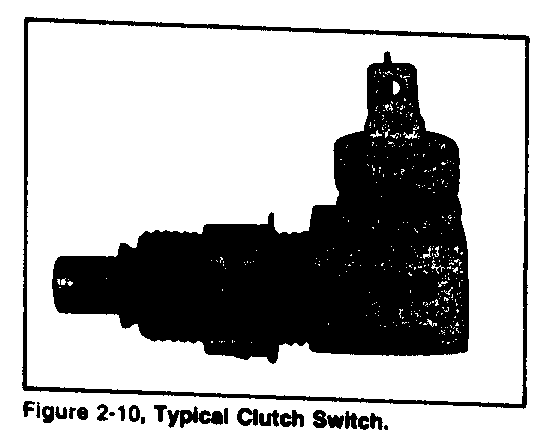
Clutch Switch
On vehicles with manual transmissiosn, an electric Clutch Switch (figure 2-10) is used. Depressing the clutch for up or downshifting a manual transmission disengages the cruise function. The cruise function remains disengaged after the clutch pedal is released.
Servo Unit
The Servo (figure 2-11) consists of a vacuum operated diaphragm, a normally open solenoid valve to vent the diaphragm chamber to atmosphere, a normally closed solenoid valve to connect the diaphragm chamber to the vacuum source, and a variable inductance position sensor. The servo operates the throttle in response to signals from the electronic controller as follows:
Steady State Cruise Function - Both vacuum and vent valves are closed or sealed. The servo has a constant vacuum on the diaphragm and places no flow requirements on the vacuum source.
Vehicle Losing Speed - the controller energizes the vacuum solenoid to open the vacuum vlave to the vacuum source. This increases the vacuum level in the servo to increase the throttle angle ..... the vent valve remains closed.
Vehicle Gaining Speed - The controller de-energizes the vent solenoid to open the vent valve to the atmosphere which reduces vacuum in the servo and allows the throttle return spring to decrease the throttle angle....the vacuum valve remains closed.
Vacuum Accumulator
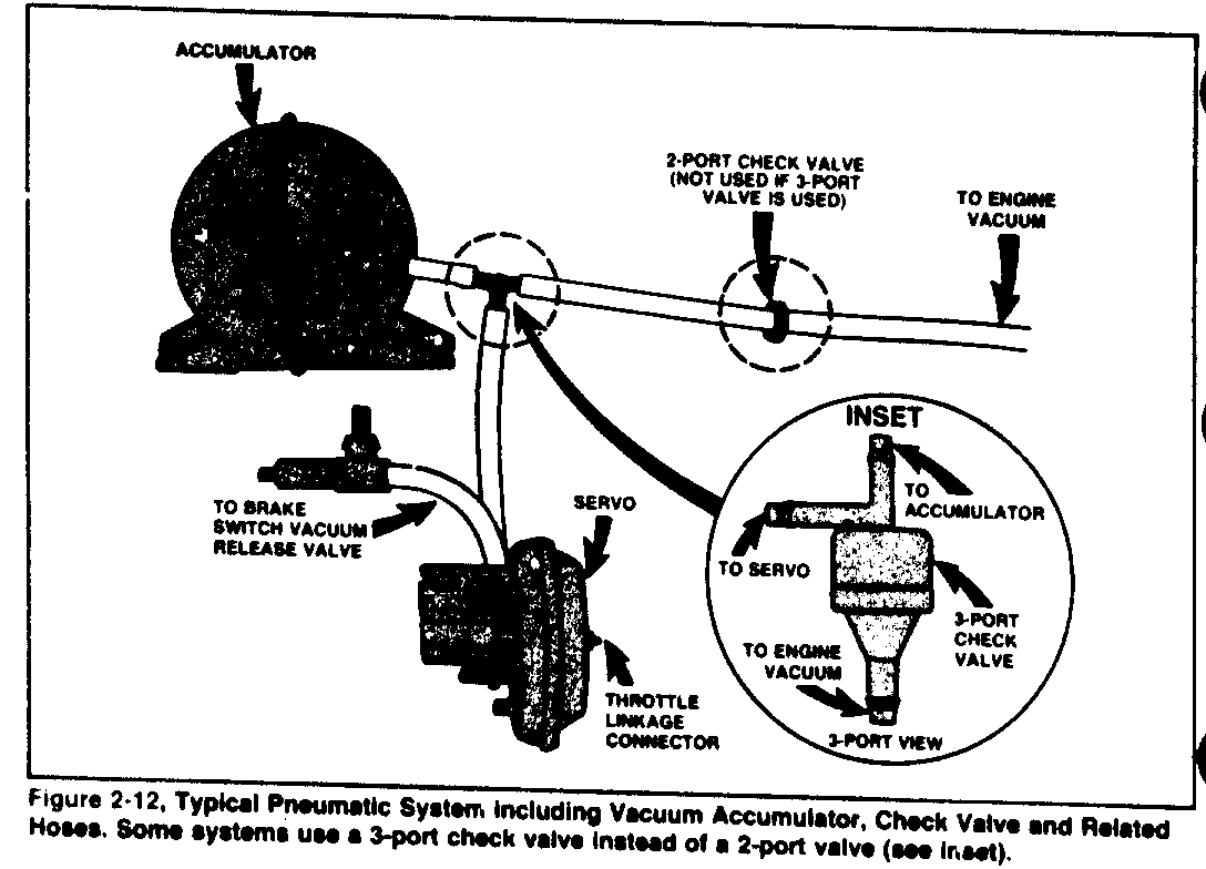
For acceptable cruise performance in vehicles with low manifold vacuum at road load, a Vacuum Accumulator (figure 2-12) is used. The Accumulator is attached to the intake manifold through a check valve and "stores" the high vacuum level that is available during periods of low engine loading. The system operates on accumulator vacuum, when higher than manifold vacuum.
The Vacuum Accumulator or check valve is not used with diesel engines.
Harness Adapter
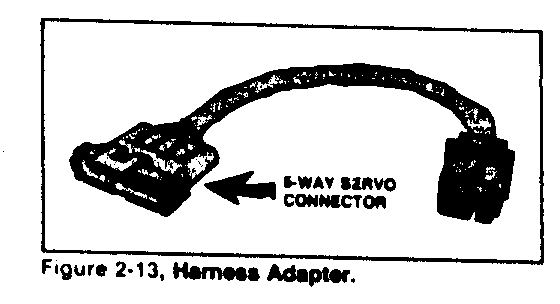
The Harness Adapter (figure 2-13) is used on some CUSTOM Cruise III appication to connect the Harness Assembly to the Servo Unit.
3. How the System Operates
Electrical/Vacuum System Operation
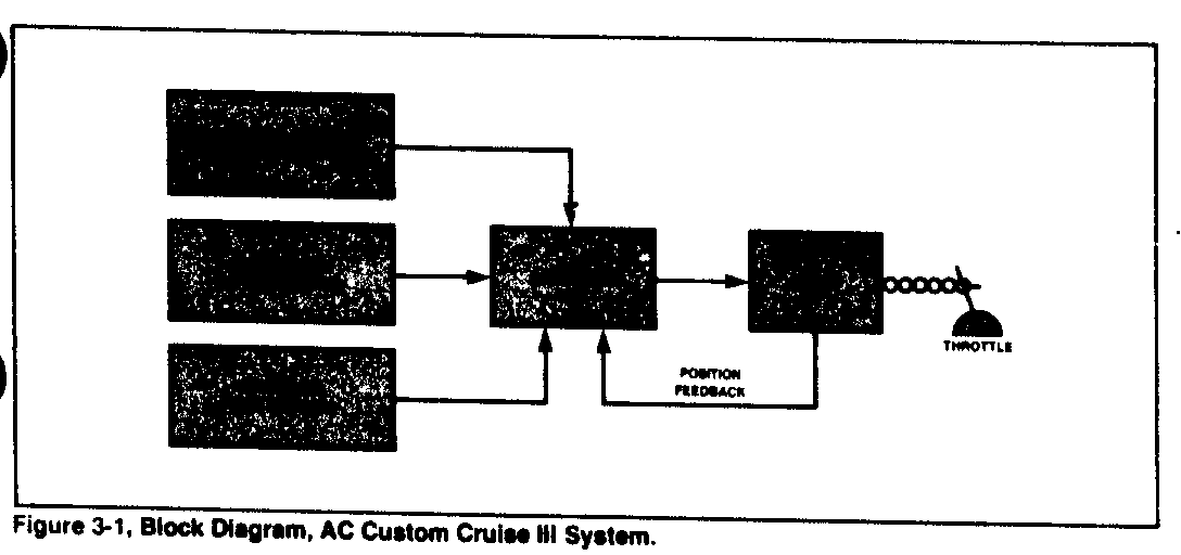
Figure 3-1 is a block diagram illustrating component relationships in the AC Custom Cruise III system.
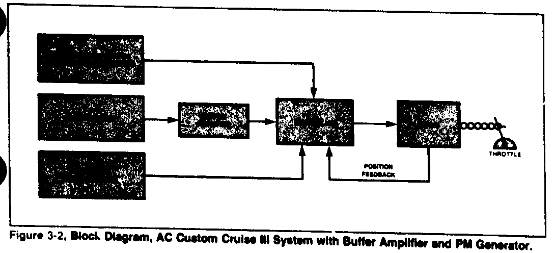
The servo vent solenoid valve and servo vacuum solenoid valve control the vacuum level in the servo in response to information from the electronic controller. The servo, in turn, controls the throttle position.
The electronic controller receives input signals from the mode control switches, brake release switch, speedometer buffer amplifier and a position feedback signal from the servo position sensor.
Figure 3-2 shows the same block diagram (as figure 3-1) except that the speed sensor is a PM generator which supplies a speed signal of 1.112 Hz per MPH to a buffer amplifier. The buffer in turn divides the signal by two to provide a frequency of 0.556 Hz per MPH to the electronic control module for cruise operation.
System Configurations
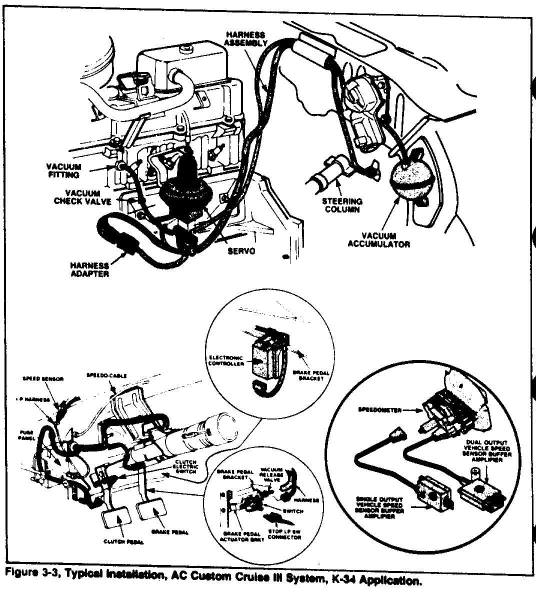
Figure 3-3 shows a typical AC Custom Cruise III (K-34) system installation.
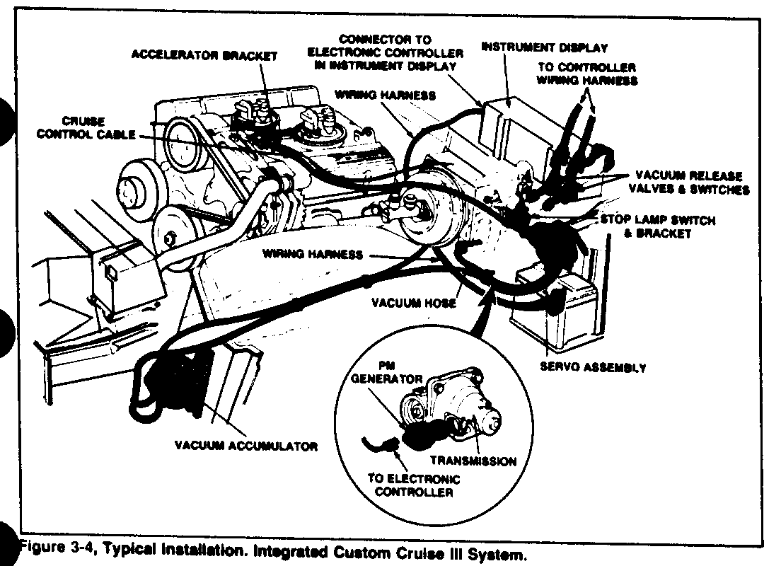
Figure 3-4 illustrates a typical AC Integrated Custom Cruise III System installation. Note that the electronic circuitry is located in the instrument display. The speed sensor, a PM Generator, is driven by the transmission.
Circuit Schematics
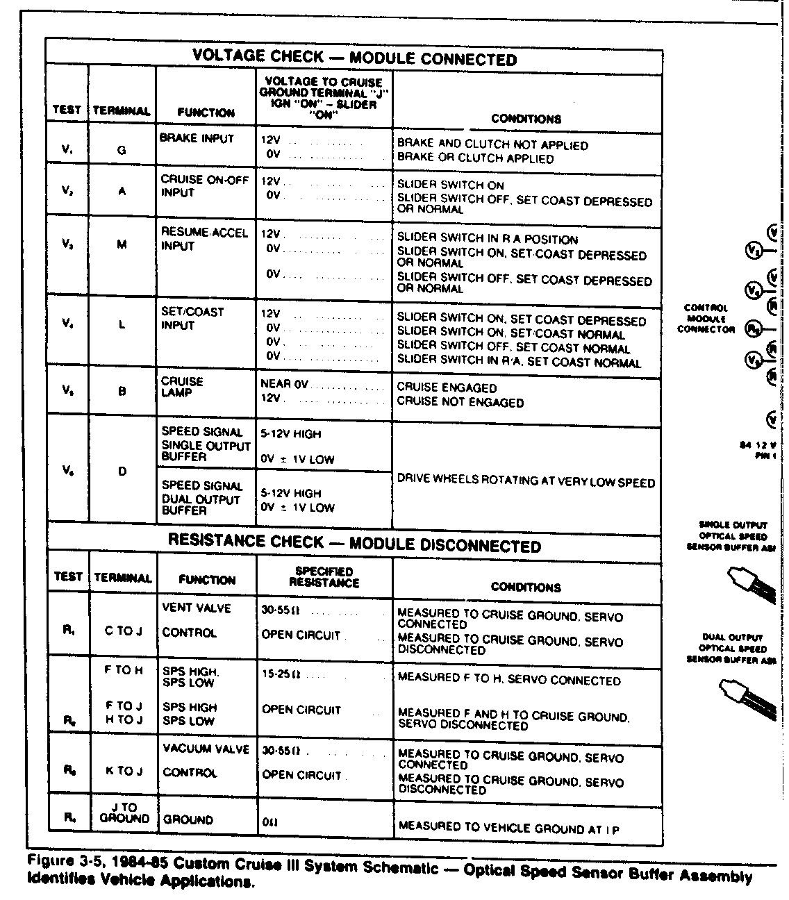
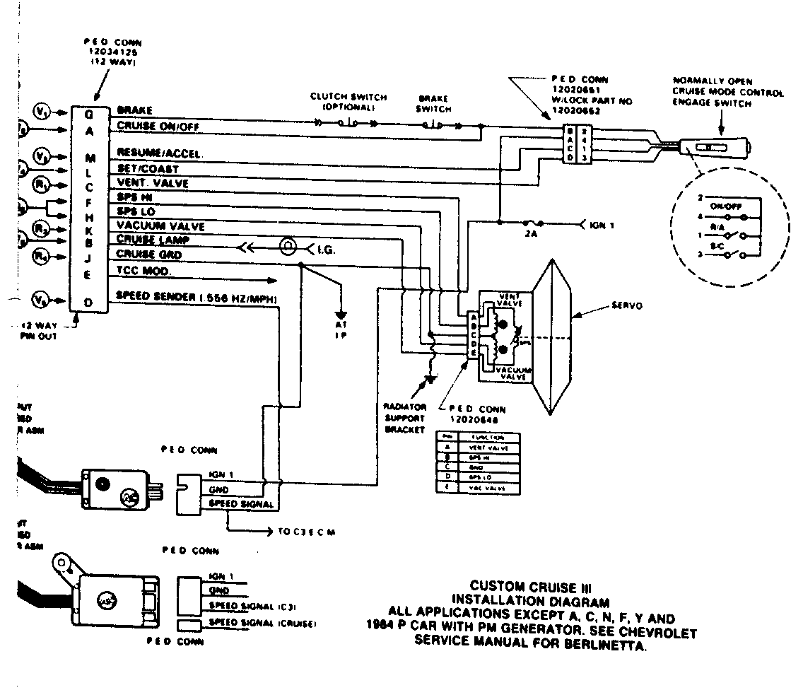
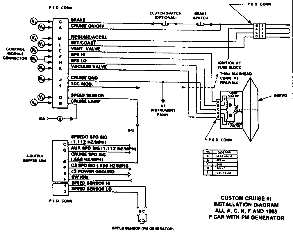
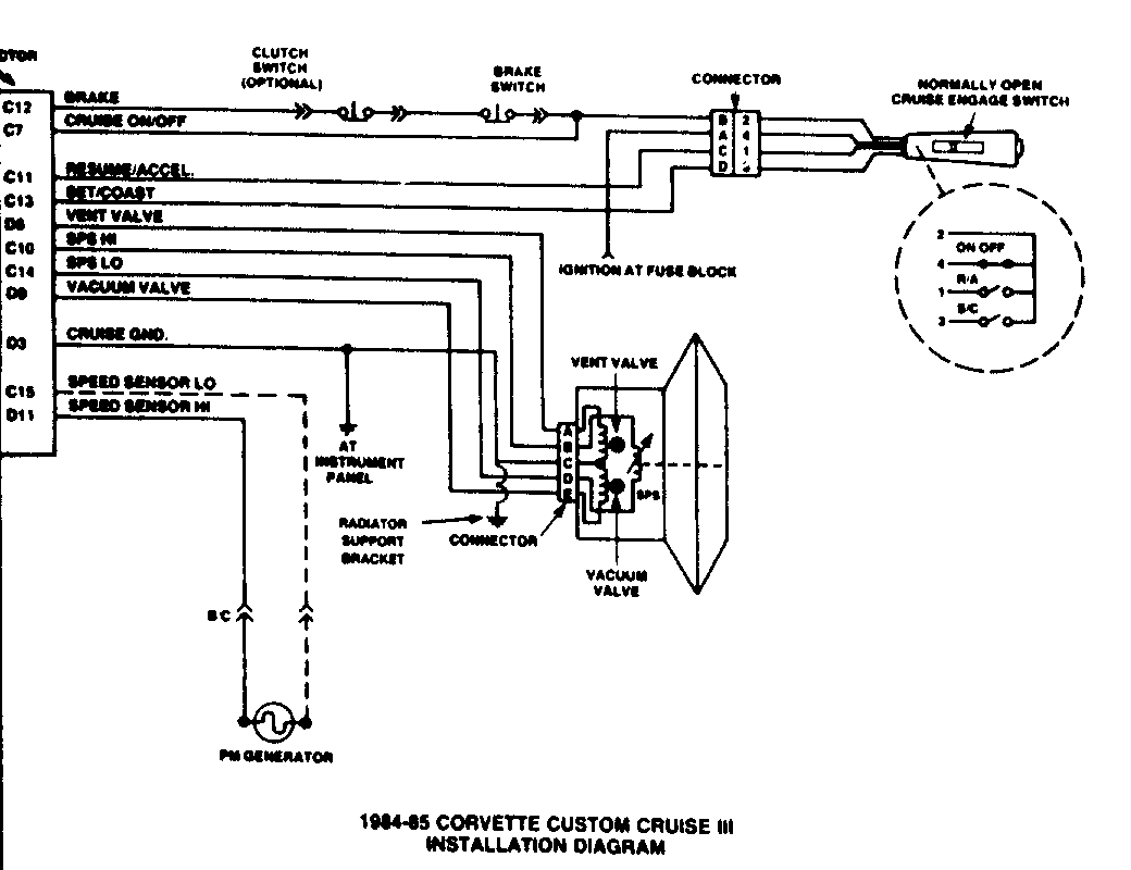
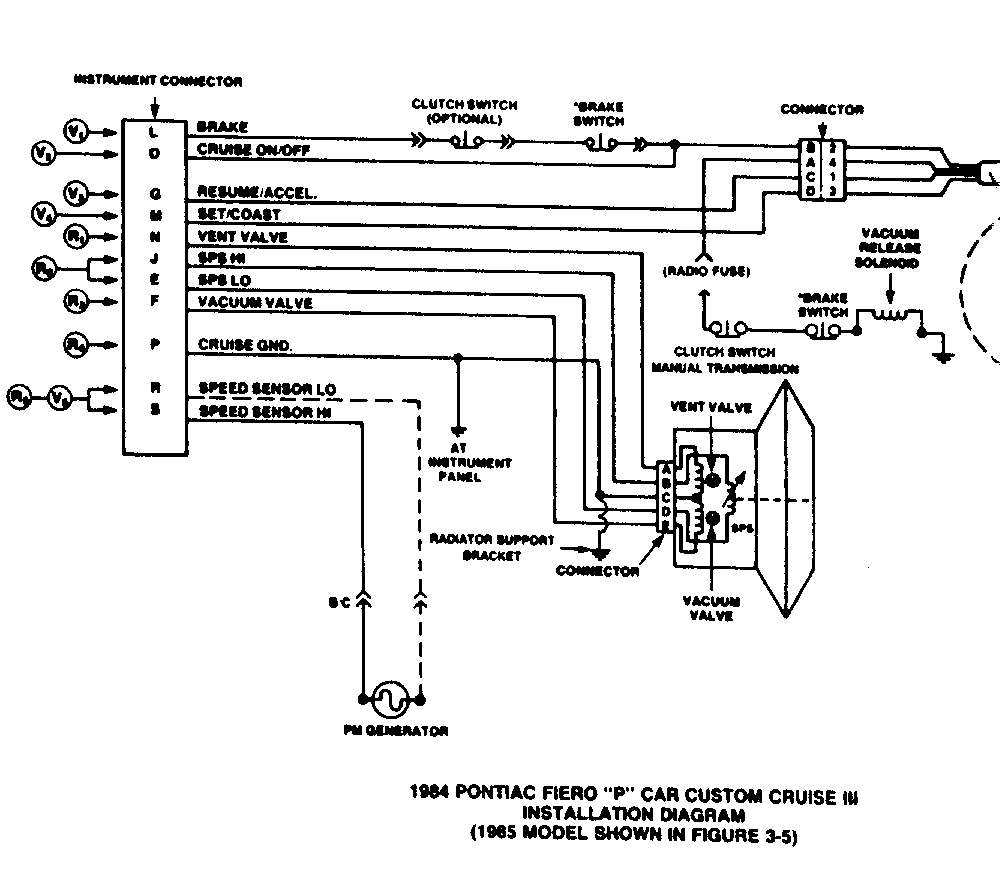
The various AC Custom Cruise III trypical circuit schematics are shown in figures 3-5, 3-6, 3-7 and 3-8.
3. How the System Operates
Refer to figure 3-5 and figure 3-6.
When the ignition switch is ON, battery voltage is applied to the Mode Control Switch and the Buffer Amplifier.
When the slide switch is in the ON position, battery voltage is applied to terminal "A" of the control module connector. If the brake and/or clutch are not applied, battery voltage is present at terminal "G".
When the R/A, Resume/Accel slider is in the R/A position, battery voltage is applied to terminal "M".
When the SET/COAST button is depressed, battery voltage is applied to terminal "L".
The controller sends a vent valve signal, it flows from cruise module terminal "C: to servo terminal "A: then through the servo vent coil to servo terminal "C", then to Cruise Ground (module terminal "J") then to the IP (instrument panel).
Servo terminals "B" and "D" complete the SPS, servo position cricuit. The servo position circuit originates at terminal "F" control module connector, flows through servo terminal "B", through the SPS coil to servo terminal "D", then to terminal "H" at the control module connector.
The controller sends a vacuum valve signal which originates at terminal "K" and flows to servo terminal "E", through the servo vacuum coil to servo terminal "C", then to control module connector terminal "J"....cruise ground at the I.P. (instrument panel).
A cruise lamp is used on some 1984-85 applications. The control module terminal "B" (figure 3-6) is used to ground the cruise lamp.
Control module connector terminal "J" is Cruise Ground. On 1984-85 Corvette (figure 3-7) Cruise Ground is on terminal "D-3". On 1984 Pontiac Fiero "P" car (figure 3-8) Cruise Ground is on controller terminal "P".
Control module connector terminal "D" (figure 3-5) is the speed sender terminal. In operation, voltage will oscillate between a high of 4 to 12 volts and a low of near ground, depending on other uses of this signal.
Control module connector terminal "E" is intended for an optional cruise signal (figures 3-5 and 3-6). "Cruise" mode to the ECM modifies TCC scheduling during the cruise mode. it operates the same as terminal "B".
The circuit shown in figure 3-6 is very similar to the circuit shown in figure 3-5.
1. Terminal identification at the controller is identified by name....i.e. "Brake", "Cruise On-Off", etc.
2. The Buffer Amplifier, located between the PM Generator and Control Moduel Connector has a variable signal output....1.112 Hz for speedo speed signal, 0.556 Hz for the cruise signal.
Voltage Check - Module Connected
Voltage to Cruise Ground Terminal "J" Ign "ON" - Slider Test Terminal Function "ON" Conditions ---- -------- -------- ---- ----------
Brake Input 12V Brake and clutch not applied V G 0V Brake or clutch applied
Cruise On-Off 12V Slider Switch on V A Input 0V Slider switch off, set coast depressed or normal
Resume/Accel 12V Slider Switch in R A Position V M Input 0V Slider switch on, set coast depressed or normal 0V Slider switch off, set coast depressed or normal
Set Coast 12V Slider switch on, set coast depressed V L Input 0V Slider switch on set coast normal 0V Slider switch off set coast normal 0V Slider switch in R/A set coast normal
Cruise Near OV Cruise engaged V B Lamp 12V Cruise not engaged
Speed signal 5-12 High Single output Buffer OV +/- 1V Low Drive sheels rotating at very low speed
V D Speed signal 5-12 V High Dual output OV +/- 1V low Buffer
Resistance Check Module Disconnected
Specified Test Terminal Function Resistance Condition ---- -------- -------- ---------- --------- Vent Valve 30-55 Measured to cruise ground, servo connected R C to J Control Open Circuit Measured to cruise ground, servo disconnected.
F to H SPS High 15-25 Measured F to H Servo connected SPS Low
F to J SPS High Open Circuit Measured F and H to Cruise ground R H to J SPS Low Servo disconnected
Vacuum Valve 30-55 Measured to cruise ground, servo connected R K to J Control Open Circuit Measured to cruise ground, servo disconnected
J to R ground Ground Measured to vehicle ground at IP
General Motors bulletins are intended for use by professional technicians, not a "do-it-yourselfer". They are written to inform those technicians of conditions that may occur on some vehicles, or to provide information that could assist in the proper service of a vehicle. Properly trained technicians have the equipment, tools, safety instructions and know-how to do a job properly and safely. If a condition is described, do not assume that the bulletin applies to your vehicle, or that your vehicle will have that condition. See a General Motors dealer servicing your brand of General Motors vehicle for information on whether your vehicle may benefit from the information.
