TRANSAXLE REMAINS IN 3RD GEAR WHEN 3-2 DOWNSHIFT IS DESIRED

SUBJECT: TRANSAXLE REMAINS IN 3RD GEAR WHEN 3-2 DOWNSHIFT IS DESIRED (CODE P029) (REPLACE CHANNEL PLATE/CONTROL VALVE HOUSING ASSEMBLY)
VEHICLES AFFECTED: 1993 "E,K,V" MODELS WITH 4T80E TRANSAXLE (RPO MH1)
APPLICATION:
----------- 1993 Cadillac E, K, V-Car Transaxle Models: 2AJN, 3AJN, 3ARN, 3AAN
CONDITION:
--------- Some vehicles equipped with a Hydra-matic 4T80-E (RPO MH1) transaxle built on or before Julian Date 318 (November 14, 1992) may remain in 3rd gear when a 3-2 downshift is desired. A code P029 may be set by the PCM due to the no 3-2 downshift condition.
CAUSE:
----- The condition may be caused by the 2-3 valve train which is located within the Lower Control Valve Assembly. The 3-2 valve train is manufactured with a valve interlock feature. Some valves may have been manufactured with the interlock misaligned, causing the 3-2 valve train to bind in the valve body bore.
CORRECTION:
---------- Diagnosis:
Access vehicle diagnostic system. (You must understand how to use the on-board diagnostic system in order to properly diagnose this powertrain.)
To diagnosis this condition, perform the following procedure:
To Enter Diagnostics Proceed as Follows
1. Start vehicle.
2. Push the "OFF" and "WARM" buttons on the Climate Control Panel simultaneously and hold until the segment check appears on the IPC and Combo Panel.
3. Select "PCM" data. (PCM data will be the first available system after trouble codes have been displayed.)
4. Once "PCM" data is selected, select test parameter "PD76 Transaxle Gear Ratio". Depressing the "LO" button on the Electronic Climate Control Display Panel will step through each available parameter in PCM data.
5. Monitor solenoid state and gear ratio status. Shift Solenoid "A" is the "OFF" light and Shift Solenoid "B" is the 'ECON' light for the V-Car, and "DEFOG" (Word not symbol) for the E, K-Car. (The lights can be viewed on the Electronic Climate Control Display.)
NOTE: Light on indicates the solenoid is energized, light off indicates the solenoid is de-energized.
6. When the 3-2 shift is completed, both the "OFF" and "ECON" or "DEFOG" lights on the Electronic Climate Control Display should be off (light off).
7. If the 2-3 valve sticks, the "OFF" and "ECON" or "DEFOG" lights will still go out (light off), but the ratio will be 1.00. This indicates the PCM commanded the transaxle into 2nd gear but stayed in 3rd gear due to a stuck 2-3 shift valve.
Road Test:
NOTE: Road test should only be performed when traffic and road conditions permit. Observe all traffic safety regulations.
1. Verify vehicle is in proper diagnostic mode.
2. Move gear selector into D4 (overdrive range).
3. Accelerate vehicle up to 65 kph (40 mph) [accelerate under Light Throttle DO NOT SNAP THROTTLE OPEN]. Verify vehicle is in 4th gear by checking solenoid state on Electronic Climate Control Display. (Solenoid "A' energized, Solenoid "B" energized.)
4. Remove foot from accelerator pedal completely (zero throttle).
5. Now, depress accelerator pedal (with medium speed) to approximately 30 percent of accelerator pedal travel (DO NOT SNAP IT OPEN), during the same motion, accelerate to Wide Open Throttle (WOT) to force a 3-2 downshift.
NOTE: Throttle movement from ZERO THROTTLE to WOT must be a continuous movement. (Example: From ZERO THROTTLE to 30 percent of accelerator pedal should be done at medium speed. Without pausing, the remaining 70 percent of accelerator pedal movement (WOT) should be done at a fast speed.) Vehicle speed should not need to exceed 88 kph (55 mph).
6. Observe solenoid state. (See steps 6 and 7 above for solenoid operation explanation.)
SERVICE PROCEDURE:
(Remove or Disconnect)
If the vehicle indicates that the 3-2 shift valve is sticking due to the performance of the procedure above, the Channel Plate/ Control Valve and Housing Assembly (903) must be removed and replaced. To replace the Channel Plate/Control Valve and Housing Assembly (903), perform the following procedure:
1. Raise vehicle and support.
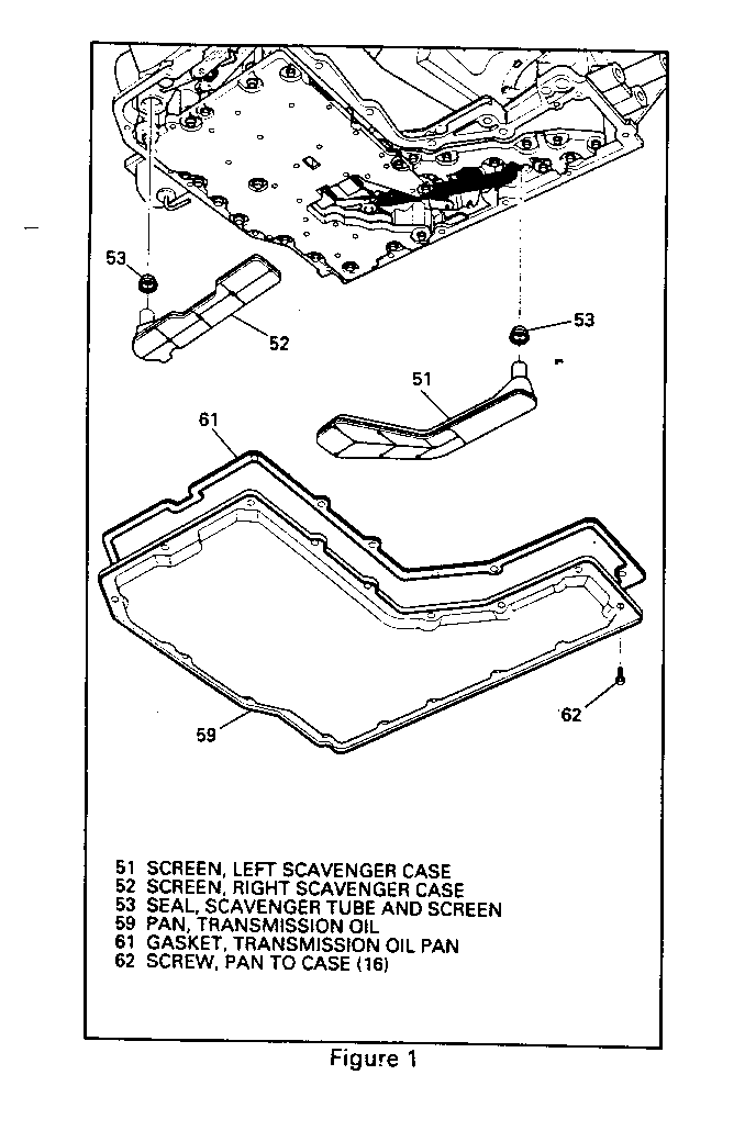
2. Place drain pan under transaxle bottom pan to catch fluid. Loosen the sixteen bottom pan bolts (62) and remove bottom pan (59) and bottom pan seal (61). Allow transaxle to drain completely.
Important: Bottom pan seal is not reusable. Replace with new part after removing bottom pan for any service. (Bottom pan gasket and scavenger screen and bolt package will need to be ordered. See service parts for more information.)
3. Remove left and right scavenger screens (51, 52) and seals (53) and discard. Use caution when removing seals. It is very important that the case is not scored or damaged when seals are removed.
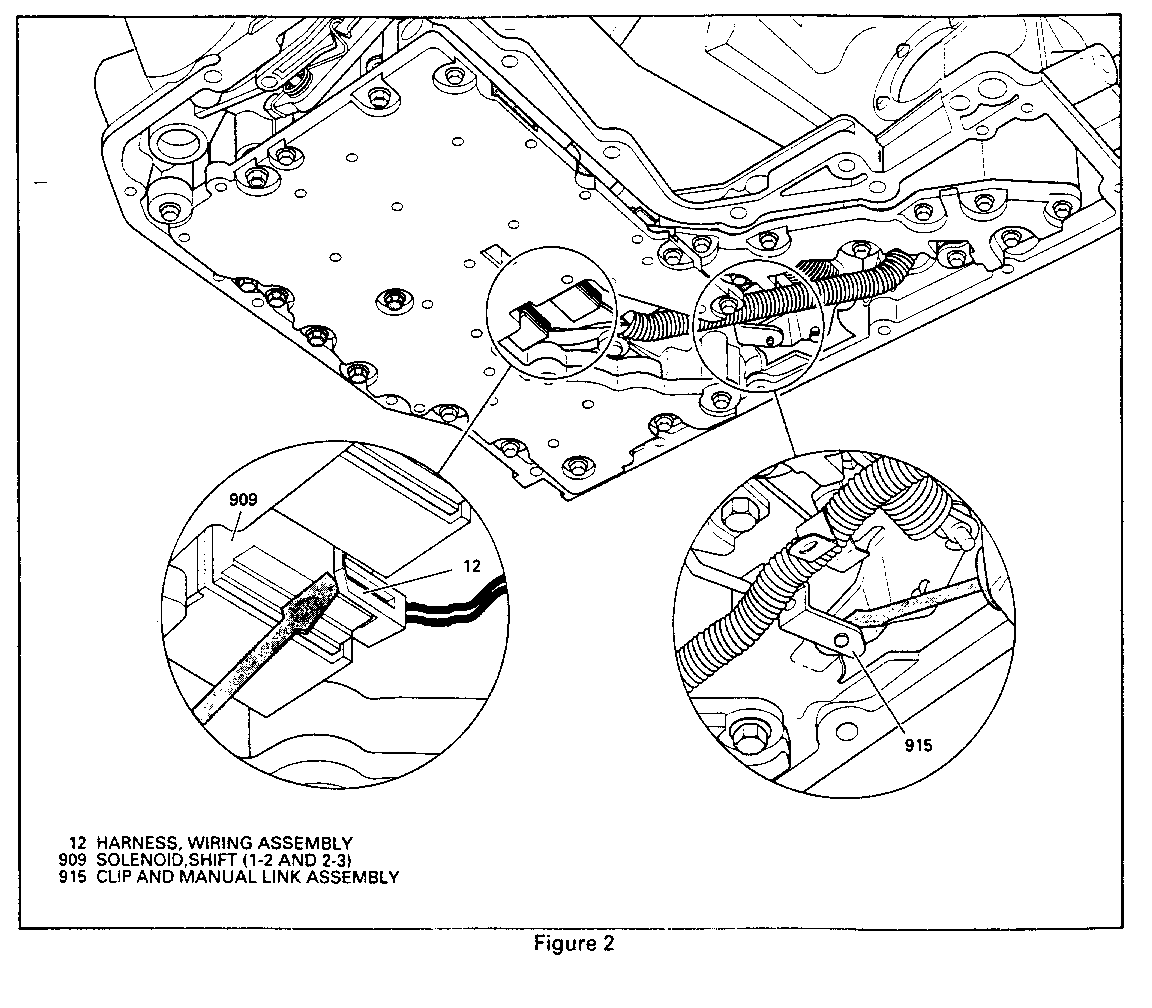
4. Disconnect "A" and "B" shift solenoids and transaxle pressure switch connectors (Figure 2).
5. Disconnect manual valve linkage clip (915) (Figure 2).
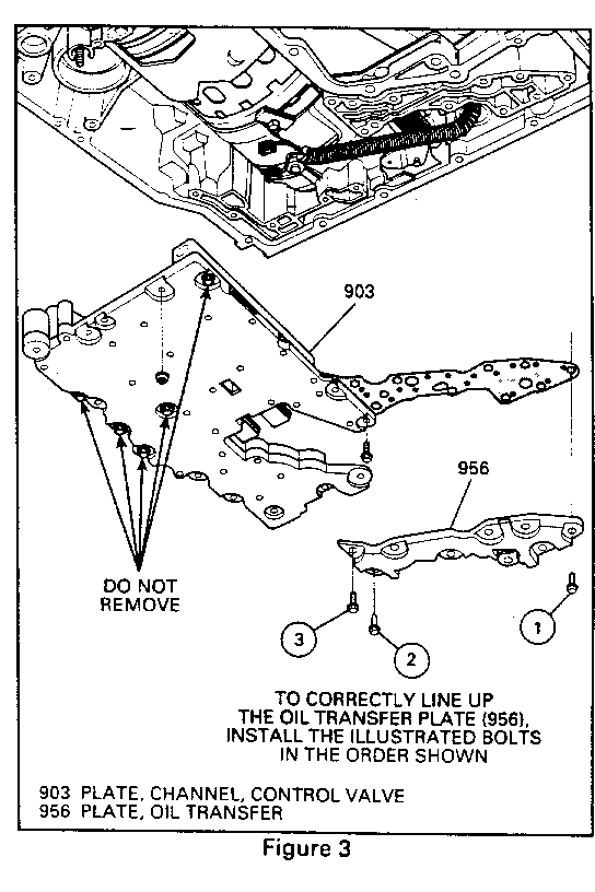
6. Remove nine oil transfer plate bolts (534) and oil transfer plate (956) (Figure 3).
7. Remove ten lower channel plate bolts (534), two nuts (955), and lower channel plate control valve, and accumulator assembly from transaxle. (DO NOT REMOVE indicated bolts in lower channel plate (Figure 3)).
SERVICE PROCEDURE:
(Install or Connect)
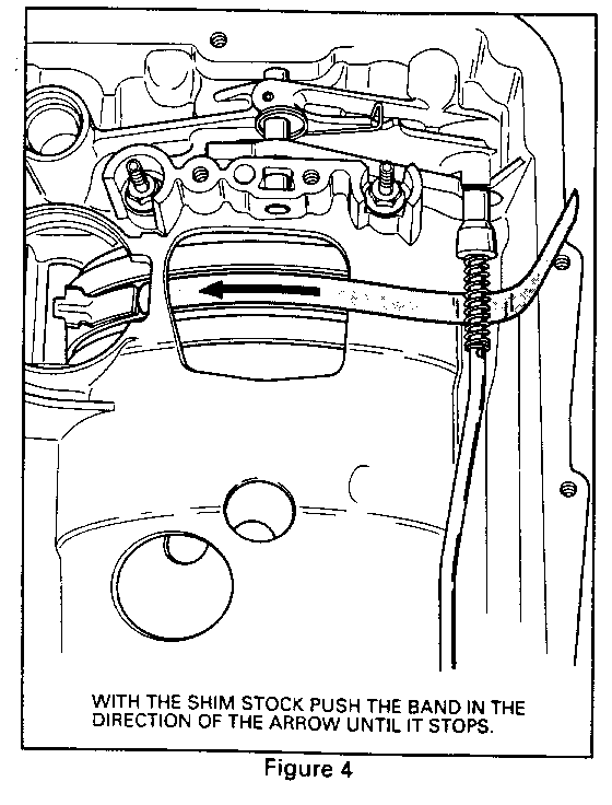
1. Centre the low reverse band position and low reverse band using a 30 cm (12 inch) length of 0.5 mm (.020") shim stock. A mispositioned low reverse band during assembly will result in a no first gear/no engine braking/no reverse condition (Figure 4).
2. Place lower channel plate/control valve and accumulator assembly in transaxle using the forward support studs to locate.
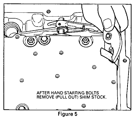
3. Hand start ten bolts and two nuts in channel plate. Bolts without flanges are located next to oil transfer plate. Torque bolts and nuts to 12 N.m (106 lbs. ft.). Remove shim stock (Figure 5).
4. Install oil transfer plate and hand start nine bolts. Torque to 12 N.m (106 lbs. ft.) (Figure 3).
5. Connect manual valve (915) to detent lever (17) (Figure 2).
6. Route wiring harness under spacer plate rib and detent lever. Connect wiring harness to "A" and "B" shift solenoids (909) and transaxle pressure switch (936) (Figure 2).
7. Install left and right scavenger screens (51, 52, and 53) (Figure 2).
8. Remove any residual transaxle fluid from gasket sealing surface of the case, the outside surface of the case, case bolts, bottom pan, and bolt holes. Use a rubber tipped air hose on the case bolt holes to remove fluid, if necessary. All of the bottom pan bolts MUST be completely dry before installation.
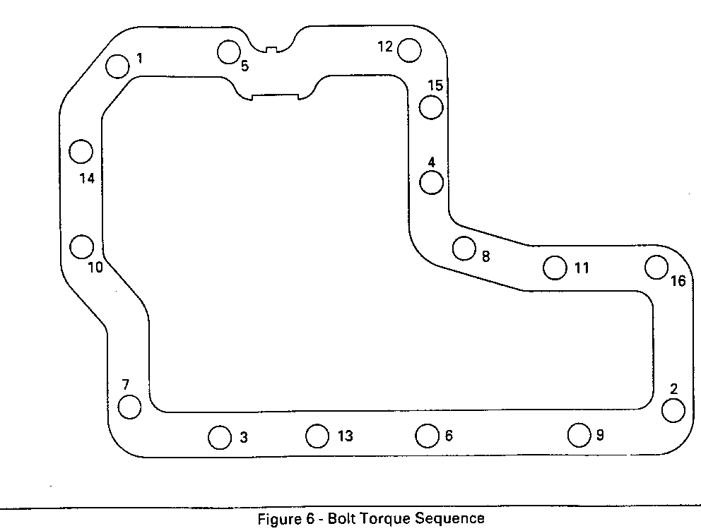
9. Position the new gasket and bottom pan on the transaxle. Hand start all of the bottom pan bolts. (Follow the torque sequence listed in Figure 6.)
o Torque all bolts to 3 N.m (27 lbs. ft.) in the sequence shown in Figure 6, then to 6 N.m (53 lbs. ft.), then finally to 12 N.m (106 lbs. ft.).
IMPORTANT: Failure to remove oil from oil pan, case surface, and case bolt holes, will greatly reduce the efficiency of the gasket and may cause a leak in the future.
IMPORTANT: The final torque specification of 12 N.m (106 lbs. ft.) must not be exceeded. If this specification is exceeded, the bottom pan gasket and case could be damaged and a transaxle fluid leak may result.
10. Add 3.8 litres (four quarts) of transmission fluid and top off fluid levels as necessary. See fluid level checking procedure.
FLUID LEVEL CHECKING PROCEDURE:
To accurately check fluid level of the HYDRA-MATIC 4T80-E transaxle, the unit must be at normal operating temperature (82-93 degrees Celsius / 180-200 degrees Fahrenheit).
NOTE: PRESENTLY, IF THE 4T80-E IS CHECKED COLD, an incorrect fluid level will be shown on the indicator.
1. Park vehicle on a level surface (with transaxle temperature between 82-93 degrees Celsius / 180-200 degrees Fahrenheit.
2. With foot on brake, move shift level through each range, pausing for about 3 seconds in each range ending in Park.
3. Apply parking brake.
4. Let engine idle for 3 minutes.
5. Remove transaxle fluid level indicator, wipe clean and reinsert, fully twisting closed.
6. Wait 3 seconds and remove indicator.
7. Read both sides of indicator and, use lowest level. Fluid level must be within cross-hatched area.
NOTE: If the brake pedal is applied during this procedure, it may affect the fluid level reading.
SERVICE PART INFORMATION:
Description Part Number Models ----------- ----------- ------ Channel Plate/Control Valve 8684463 3AAN and Housing Assembly
Channel Plate/Control Valve 8682762 2AJH,3AJN,3ARN and Housing Assembly
Bottom Pan Gasket/Scavenger 8684953 ALL Screens and Bolts
LABOUR TIME INFORMATION:
For vehicles repaired under warranty use:
Labour Operation: K661 0 (Valve Assembly, Lower Control--Replace)
Labour Time: 1.2 hrs.
**PLEASE REFER TO FIGURE 6 - BOLT TORQUE SEQUENCE** --------------------------------------------------- 4T80-E BOTTOM PAN GASKET INSTALLATION PROCEDURE ----------------------------------------------- 1. Remove bottom pan gasket and discard.
2. Remove any residual transmission fluid from the gasket surface of the case, the bottom pan, and the screws (16). All of the screws must be completely dry upon re-installation.
3. The bottom pan screw threads in the case must be completely free of transmission fluid. Use a rubber tipped air hose to dry if necessary. Wipe any residual fluid from the outside of the case.
4. Install the new gasket and then the bottom pan and screws. The screws must be hand started and then tightened following the sequence pattern illustrated below.
5. Following the sequence pattern, Torque all screws first to 3 N-m., then all screws to 6 N-m., and finally all screws to 10-12 N-m.
IMPORTANT: The final torque specification of 10-12 N-m. must not be exceeded. If this specification is exceeded, the bottom pan gasket could be damaged and a transaxle fluid leak may result.
General Motors bulletins are intended for use by professional technicians, not a "do-it-yourselfer". They are written to inform those technicians of conditions that may occur on some vehicles, or to provide information that could assist in the proper service of a vehicle. Properly trained technicians have the equipment, tools, safety instructions and know-how to do a job properly and safely. If a condition is described, do not assume that the bulletin applies to your vehicle, or that your vehicle will have that condition. See a General Motors dealer servicing your brand of General Motors vehicle for information on whether your vehicle may benefit from the information.
