Tools Required
| • | J 35944-A Transmission Oil Cooler Flusher |
| • | J 41160 Transmission Jack Adapter |
Removal Procedure
- Remove the headlamp housing upper filler panel. Refer to Filler Panel Replacement - Upper in Body Front End.
- Remove the cross vehicle brace. Refer to Cross Vehicle Brace Replacement in Body Front End.
- Remove the air cleaner assembly. Refer to Air Cleaner Assembly Replacement in Engine Controls - 4.6L.
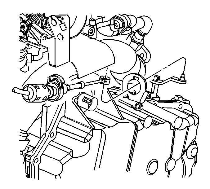
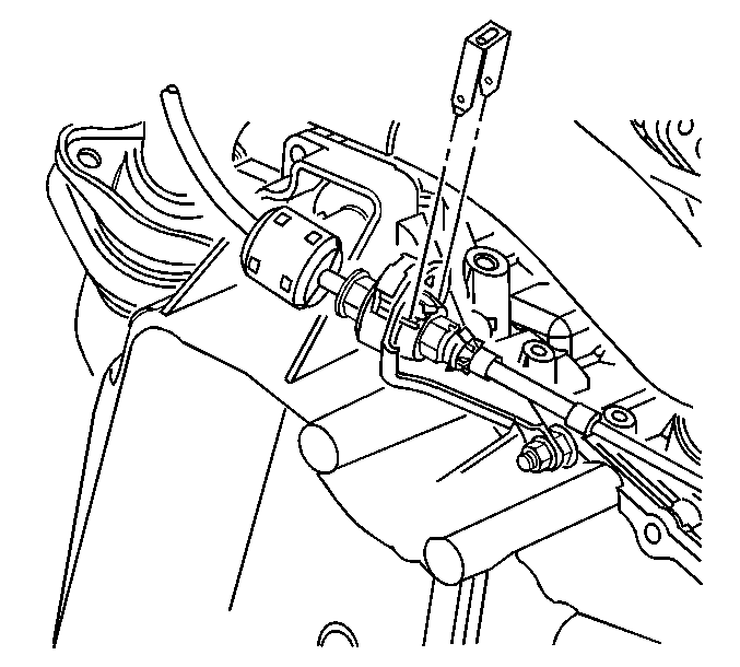
- Remove the shift control cable from the shift lever.
- Remove the shift control cable from the bracket and reposition the cable.
- Disconnect the engine mount struts. Refer to Engine Mount Strut Replacement in Engine Mechanical - 4.6L.
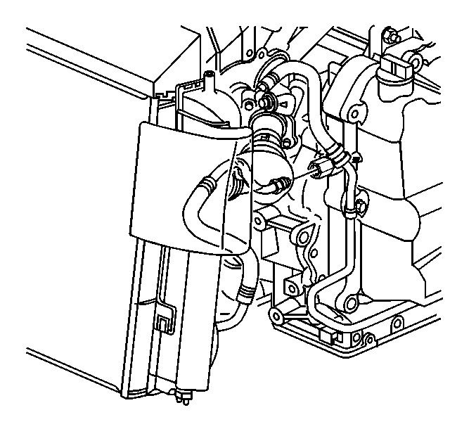
- Remove the oil cooler lines at the cooler and the oil sending line at the transmission.
- Remove the heater bypass pipe.
- Remove the power steering return hose at the auxiliary cooler.
- Install plugs in the cooler and the return hose to prevent fluid leakage or contamination.
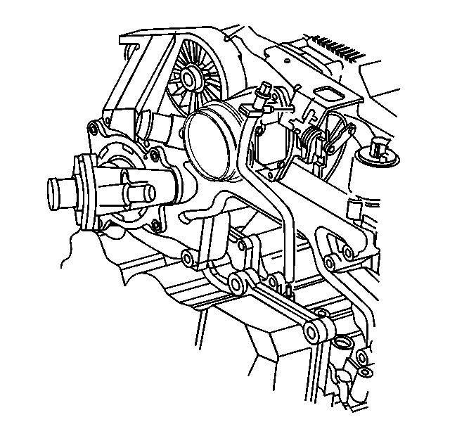
- Remove both heater tube retainers from the upper case side cover studs.
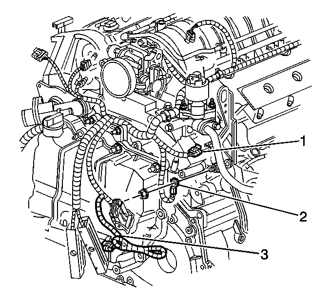
- Disconnect the electrical connector from the coolant temperature sensor (1).
- Remove the ground wire (2) from the stud near the rear transmission to engine brace.
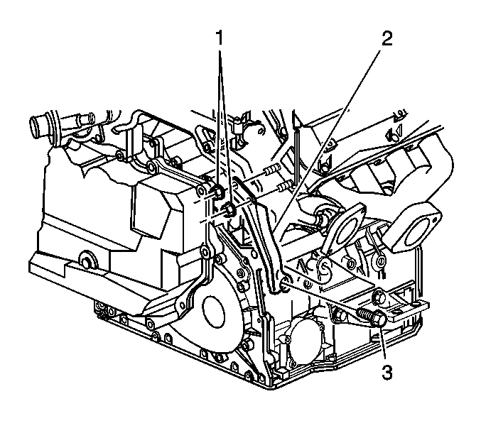
- Remove the upper nuts (1) from the rear engine to transmission brace (2).
- Disconnect the transmission vent hose at transmission.
- Carefully pull the wiring harness up from beneath the vehicle and set aside.
- Reposition the engine harness at the top of the transmission to access the upper transmission bolts.
- Remove the upper transmission bolts.
- Install the engine support fixture. Refer to Engine Support Fixture in Engine Mechanical - 4.6L.
- Raise the left side of the powertrain (the transmission side) 25.4 mm (1 in) above the powertrain resting position with the adjusting screws.
- Raise the vehicle. Refer to Lifting and Jacking the Vehicle in General Information.
- Support the vehicle with safety stands.
- Remove both drive axles. Refer to Wheel Drive Shaft Replacement in Wheel Drive Shafts.
- Remove both front wheel opening splash shields. Refer to Front Bumper Fascia Extension Replacement in Body Front End.
- Remove the engine splash shield. Refer to Engine Splash Shield Replacement in Body Front End.
- Disconnect the vehicle speed sensor connector.
- Disconnect both front suspension sensor rods from lower control arm and position aside.
- Remove the ABS modulator from the bracket and the support.
- Remove the torque converter cover. Refer to Torque Converter Cover Replacement .
- Remove the engine the transmission brace. Refer to Transmission Brace Replacement .
- Remove the front engine to transmission pencil brace.
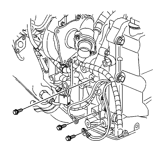
- Remove the three ground connections at the front of the transmission.
- Disconnect the transmission main harness.
- Remove the flywheel to converter bolts.
- Remove the powertrain mount nuts from the frame.
- Remove the clamp bolt (Rotate the steering intermediate shaft so that the steering gear stub shaft clamp bolt is accessible from the left wheel opening).
- Disconnect the steering intermediate shaft from the steering gear. Refer to Steering Gear Replacement in Steering System.
- Remove the electrical harness and connector from the front of the frame.
- Support the rear of frame with an adjustable jack stand.
- Remove the four rear frame bolts.
- Lower the jack stand a few inches to gain access to the power steering gear heat shield and the return line fitting.
- Remove the power steering gear heat shield and the power steering return line at the gear. Install plugs in the steering gear and pressure line in order to prevent fluid leakage or contamination.
- Remove the power steering electrical connector.
- Raise the jack stand and reinstall one rear frame bolt on each side finger tight in order to support the frame.
- Remove the jack stand.
- Remove the support frame.
- Remove the six frame mount bolts.
- Remove the lower frame and/or raise the vehicle with the steering gear attached.
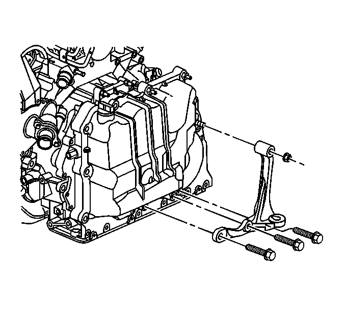
- Remove the left transmission mount and bracket from the transmission.
- Support the transaxle using the J 41160 and a suitable transmission jack.
- Secure the J 41160 to the transaxle.
- Remove the engine to transmission bolts.
- Separate the engine and transmission.
- Lower the transmission down and to the left on a slight angle so the transmission case can clear the end of the starter.
- Lower the transmission.
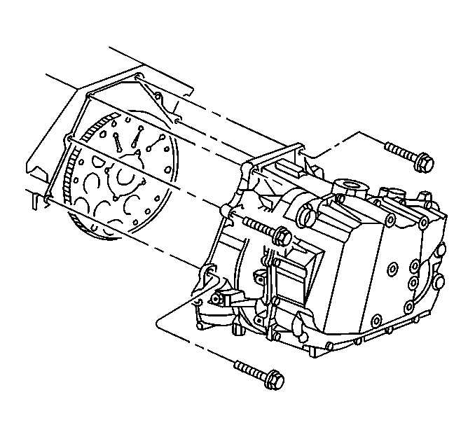

Important: Mark the flywheel to converter position so that they can be assembled in the same position.
Caution: Failure to disconnect the intermediate shaft from the rack and pinion steering gear stub shaft can result in damage to the steering gear or to the intermediate shaft. This damage may cause loss of steering control, which could result in an accident and possible personal injury.
Notice: Do not rotate the steering wheel or move the position of the steering gear once the intermediate shaft is disconnected. This will uncenter the Inflatable Restraint coil in the steering column. If the Inflatable Restraint coil becomes uncentered, it may be damaged during vehicle operation.

Installation Procedure
- Perform the oil cooler flushing procedure using the J 35944-A .
- Install the oil cooler return line to transmission.
- Transfer the mounts to the transmission.
- Raise the transaxle to the vehicle.
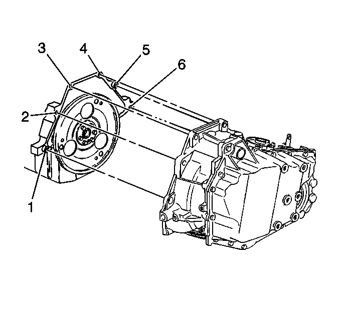
- Install the transaxle into the vehicle and align the engine alignment dowels (1 and 6).
- Install the front lower and rear upper transaxle case to engine bolts.
- Remove the transmission jack and the J 41160 .
- Install the engine to transmission brace. Refer to Transmission Brace Replacement .
- Install the left transmission bracket and mount to the transmission.
- Install the front engine to transmission pencil brace.
- Install the three ground connections at the front of the transmission.
- Connect the transmission main harness.
- Connect the upper nuts (1) from the rear engine to transmission brace (2).
- Connect both heater tube retainers from the upper case side cover studs.
- Connect the electrical connector from the coolant temperature sensor (1).
- Connect the ground wire (2) from the stud near the rear transmission to engine brace.
- Install the vehicle speed sensor connector.
- Raise the frame and/or lower the vehicle while locating the engine and transmission mount studs into the frame, harnesses at the frame, and the frame mount bolt holes to the underbody.
- Install two front and two rear frame bolts finger tight in order to support the frame.
- Remove the frame support fixture.
- Support the rear of the frame with an adjustable jack stand.
- Remove two rear frame bolts.
- Lower the jack stand a few inches in order to gain access to the power steering gear.
- Install the power steering pressure hose at the steering gear.
- Install the power steering gear and power steering gear heat shield.
- Raise the jack stand.
- Install the six frame mount bolts in the following order:
- Install the electrical harness to the front of the frame.
- Install the steering intermediate shaft to the steering gear and install the clamp bolt.
- Install the left and right transmission mount nuts and the right engine mount nuts at the frame.
- Install the flywheel to converter bolts.
- Install torque converter cover. Refer to Torque Converter Cover Replacement .
- Install the ABS modulator to the bracket.
- Install both drive axles into the transmission. Refer to Wheel Drive Shaft Replacement in Wheel Driveshaft.
- Connect both front suspension sensor rods to lower control arm.
- Install both front wheel opening splash shields. Refer to Front Bumper Fascia Extension Replacement in Body Front End.
- Install the engine splash shield. Refer to Engine Splash Shield Replacement in Body Front End.
- Lower the vehicle.
- Remove the engine support fixture. Refer to Engine Support Fixture in Engine Mechanical - 4.6L.
- Install the manual shaft linkage and nut.
- Install heater bypass pipe.
- Install the power steering hose at the auxiliary cooler.
- Install the upper transaxle case to engine bolts.
- Install the transmission cooler pipe fittings at the transmission. Install the fittings finger tight.
- Install the oil sending pipe to the transmission.
- Connect the engine mount struts. Refer to Engine Mount Strut Replacement in Engine Mechanical - 4.6L.
- Install the range control cable and bracket at the transmission.
- Connect the shift control cable to the bracket.
- Connect the shift cable to shift lever.
- Adjust the shift control cable. Refer to Range Selector Lever Cable Adjustment .
- Remove the engine support fixture.
- Install the air cleaner assembly. Refer to Air Cleaner Assembly Replacement in Engine Controls - 4.6L.
- Install the headlamp housing upper filler panel. Refer to Filler Panel Replacement - Upper in Body Front End.
- Install the cross vehicle brace. Refer to Cross Vehicle Brace Replacement .
- Flush the transmission cooler.
- Add DEXRON VI transmission fluid as required. Refer to Transfer Oil Pump Inlet Screen and Pipe Seal Replacement and Fluid Capacity Specifications .
- Check the coolant level. Refer to Cooling System Draining and Filling in Engine Cooling.
- Bleed the power steering system. Refer to Power Steering System Bleeding in Power Steering System.
- Check the front suspension alignment, adjust the toe as necessary. Refer to Wheel Alignment Measurement in Front Suspension.
- Reset the TAP values. Refer to Adapt Function .
- Reset the transmission oil life indicator. Refer to Automatic Transmission or Transaxle Fluid Change Indicator Resetting .
- Road test the vehicle and check for transaxle leaks.
Notice: Refer to Fastener Notice in the Preface section.

Tighten
Tighten the bolts to 75 N·m (55 lb ft).
Tighten
Tighten the bolts to 47 N·m (35 Ib ft).


Tighten
Tighten the fitting to 27 N·m (20 Ib ft).
| 27.1. | Left side #2 mount bolt into the body. |
| 27.2. | Left side #1 mount bolt into the body. |
| 27.3. | The remaining frame mount bolts. |
Notice: Do not rotate the steering wheel or move the position of the steering gear once the intermediate shaft is disconnected. This will uncenter the Inflatable Restraint coil in the steering column. If the Inflatable Restraint coil becomes uncentered, it may be damaged during vehicle operation.
Tighten
Tighten the bolts to 47 N·m (35 Ib ft).
Tighten
Tighten the nuts to 47 N·m (35 Ib ft).
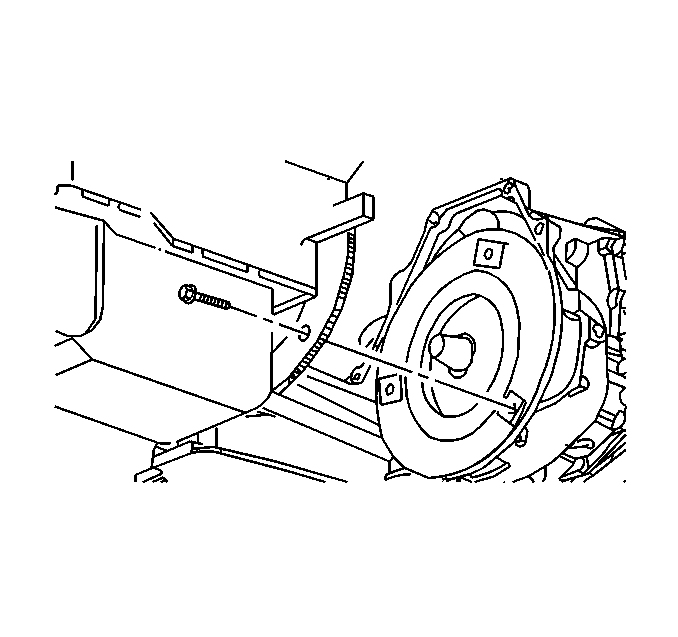
Important: Line up the flywheel and converter using the marks made at disassembly.
Tighten
Tighten the bolts to 60 N·m (44 Ib ft).
Tighten
Tighten the manual shaft nut to 20 N·m (15 Ib ft).

Tighten
Tighten the upper transaxle bolts to 75 N·m (55 lb ft).
Tighten
Tighten the cooler pipe fittings at transmission to 22 N·m (16 Ib ft).
Tighten
Tighten the bracket bolts to 12 N·m (106 Ib in).


Important: It is recommended that transmission adaptive pressure (TAP) information be reset.
Resetting the TAP values using a scan tool will erase all learned values in all cells. As a result, The ECM, PCM or TCM will need to relearn TAP values. Transmission performance may be affected as new TAP values are learned.