Tools Required
| • | EN 46109 Guide Pins |
| • | J 39946 Crankshaft Socket - 4.0L and 4.6L |
| • | J 45059 Angle Meter |
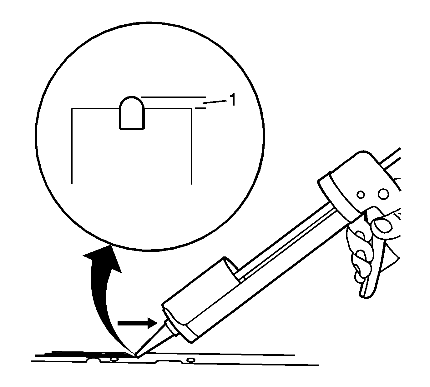
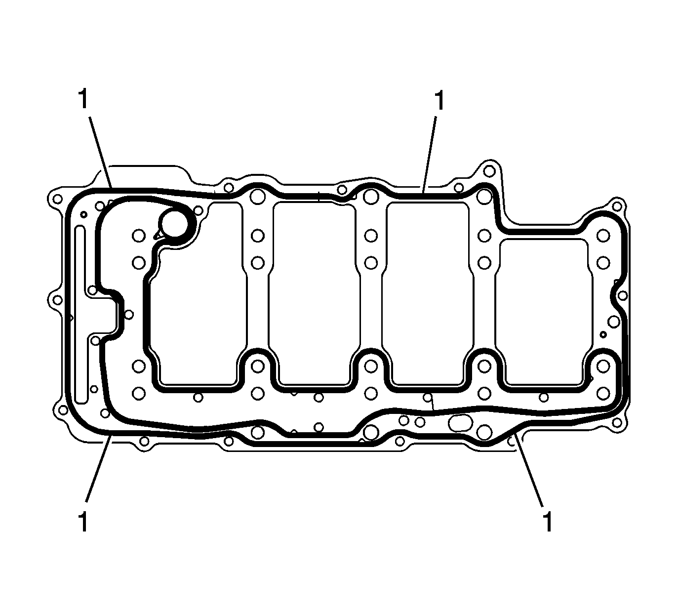
- Completely fill and slightly overfill the engine block seal groove with a continuous bead of RTV sealant GM P/N 12378521 or equivalent.
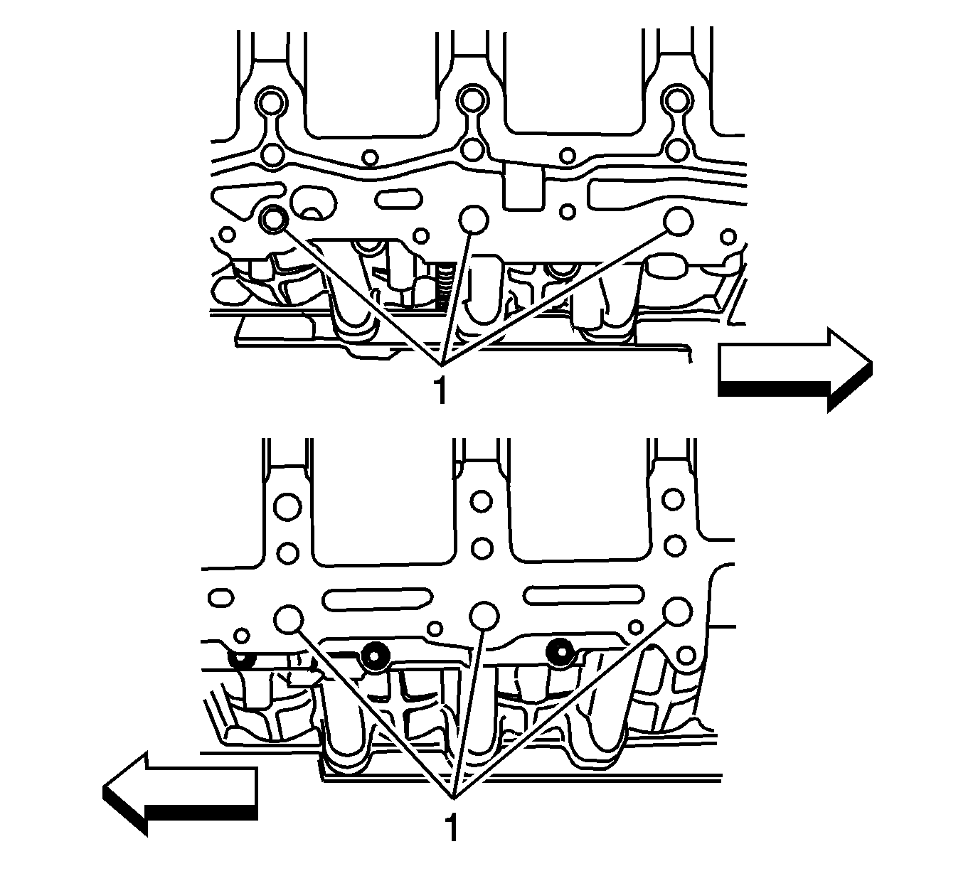
- Ensure the RTV sealant GM P/N 12378521 or equivalent bead is higher then the rail surface (1) by 3 mm (0.118 in).
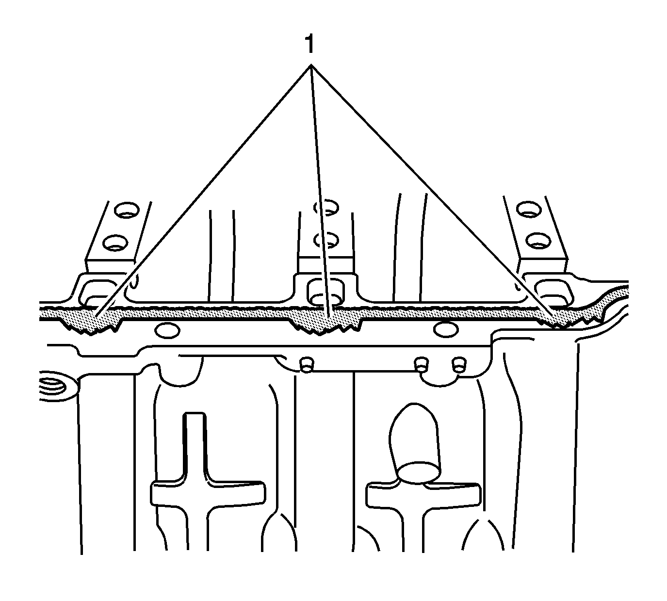
- Using a suitable tool spread the sealant in the area near the oil drain back passages (1) away from the oil drain back passages toward the outboard edge of the rail surface.
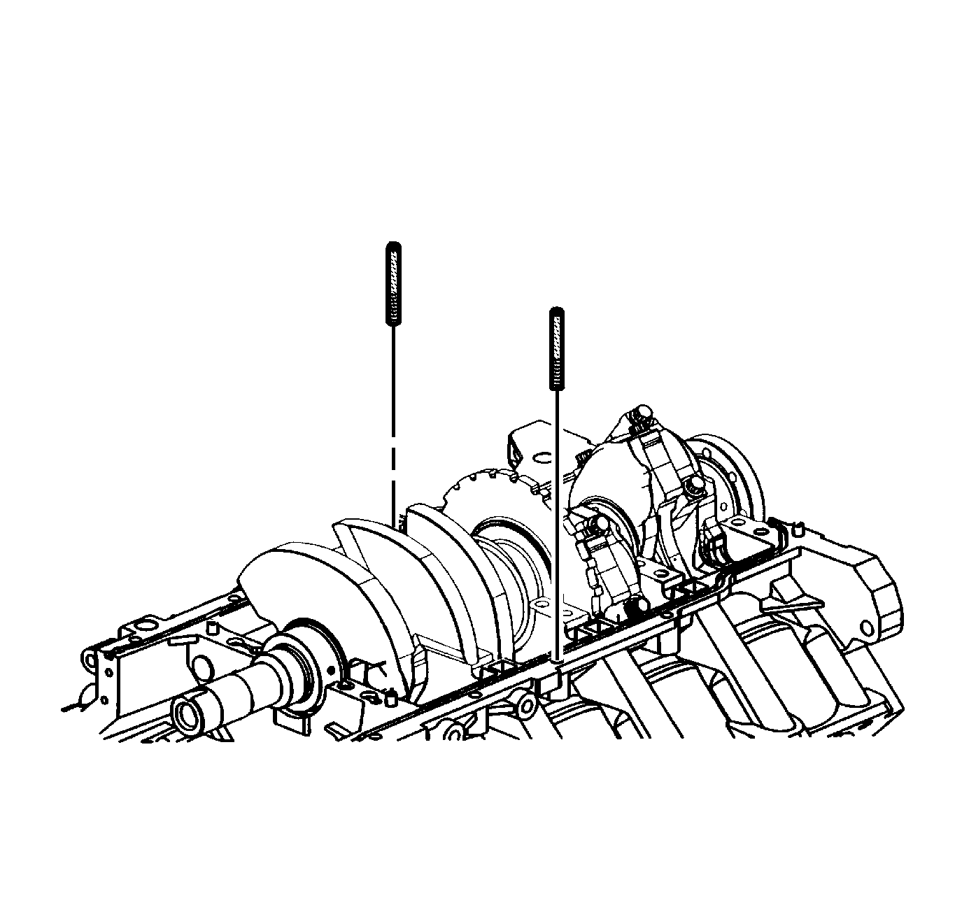
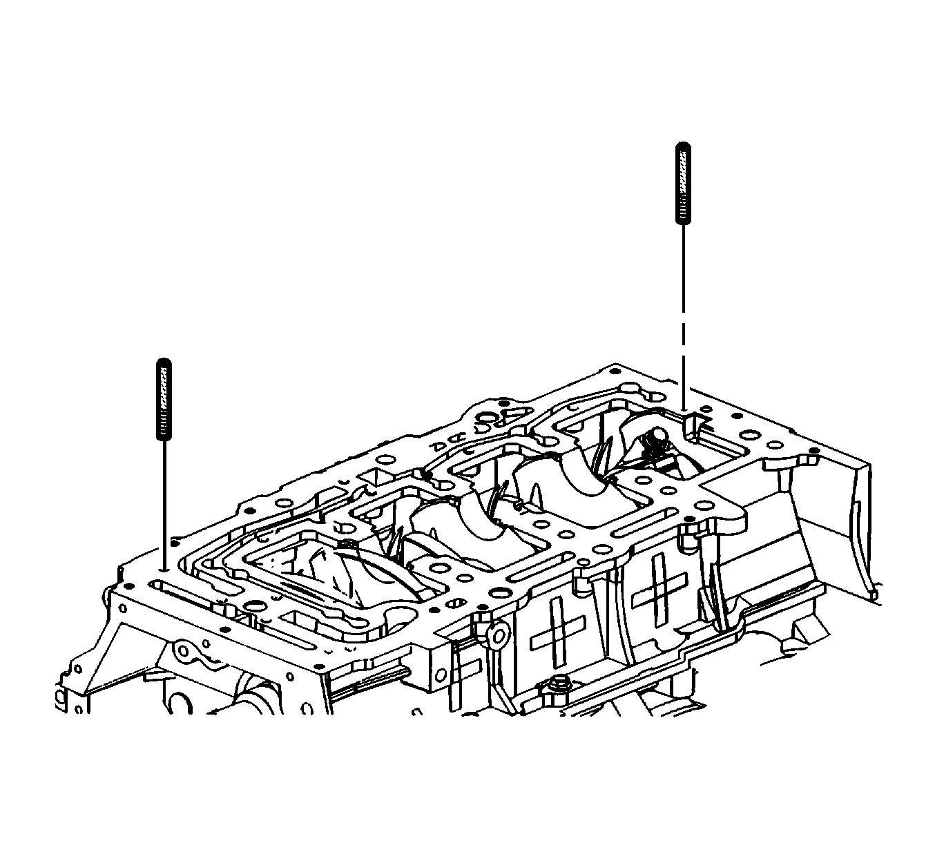
- To prevent shifting of the lower crankcase install one of the EN 46109 into a bolt hole in each rail.
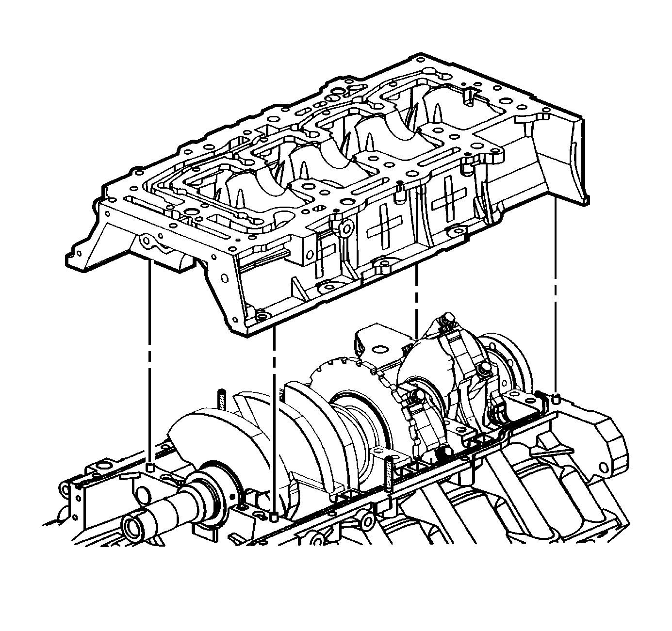
- Install the cleaned lower crankcase onto the engine.
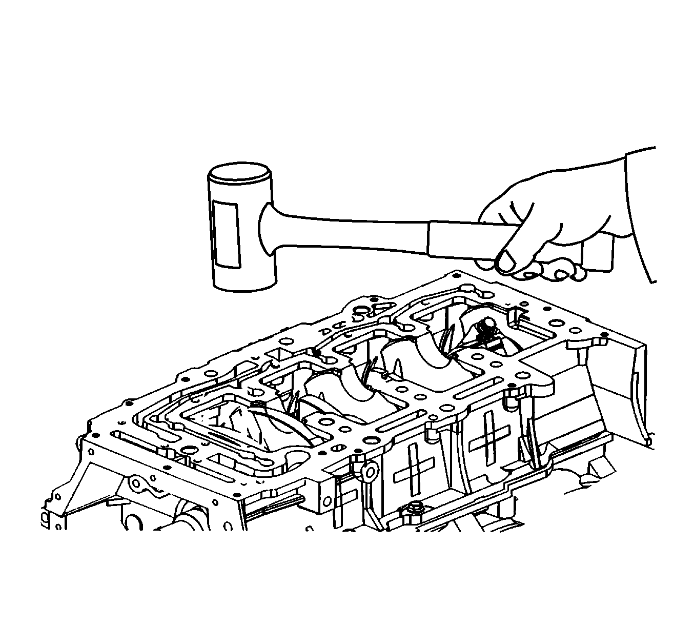
- Using a rubber mallet gently tap the lower crankcase into position.
- Remove both of the EN 46109 .
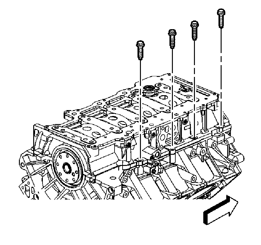
- Loosely install the crankcase perimeter bolts on the right side.
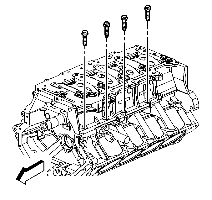
- Loosely install the crankcase perimeter bolts on the left side.
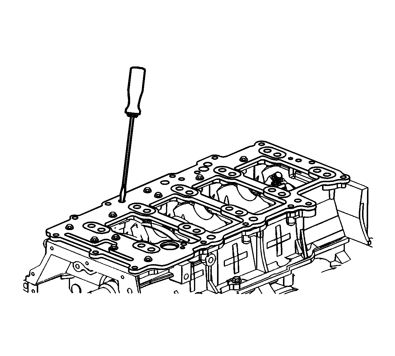
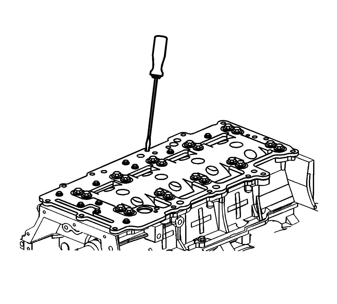
- Using a small long blade screwdriver clean out any sealant in the oil drain back passages (1).
- Using a NEW oil distribution plate place a continuous 3 mm (0.118 in) wide bead of RTV sealant GM P/N 12378521 or equivalent on top of the outer seal (1) of the oil distribution plate place.
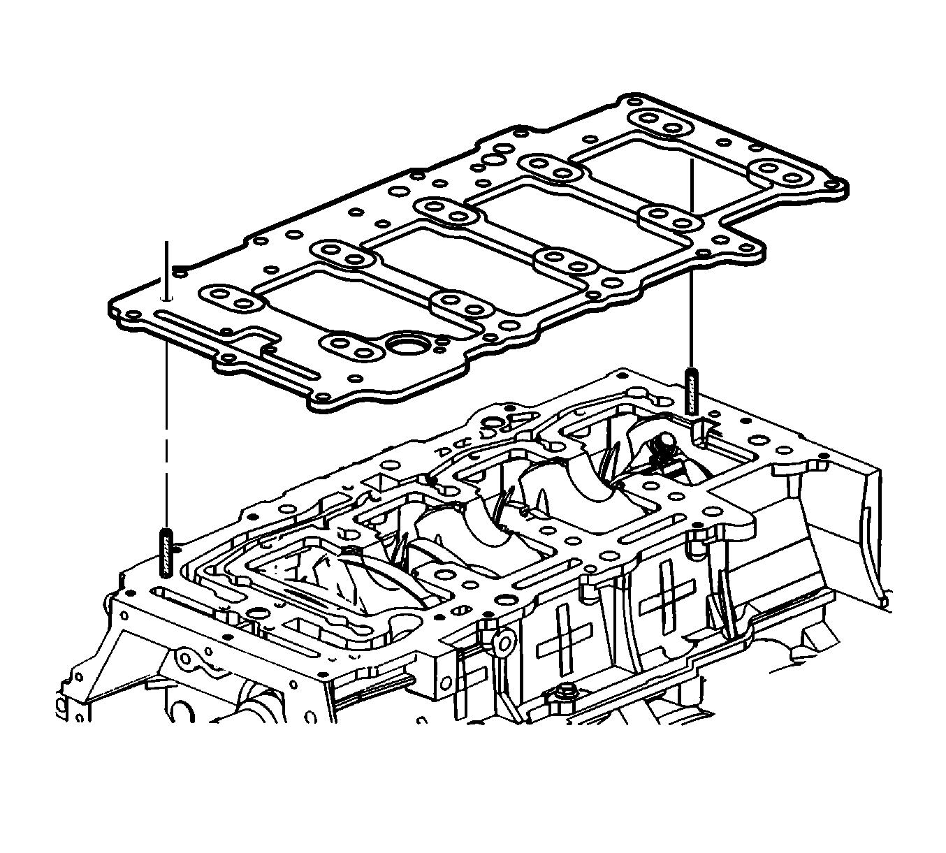
- To prevent shifting of the oil distribution plate install one of the EN 46109 into a bolt hole in each side of the lower crankcase.
- Install the NEW oil distribution plate.
- Remove both of the EN 46109 .
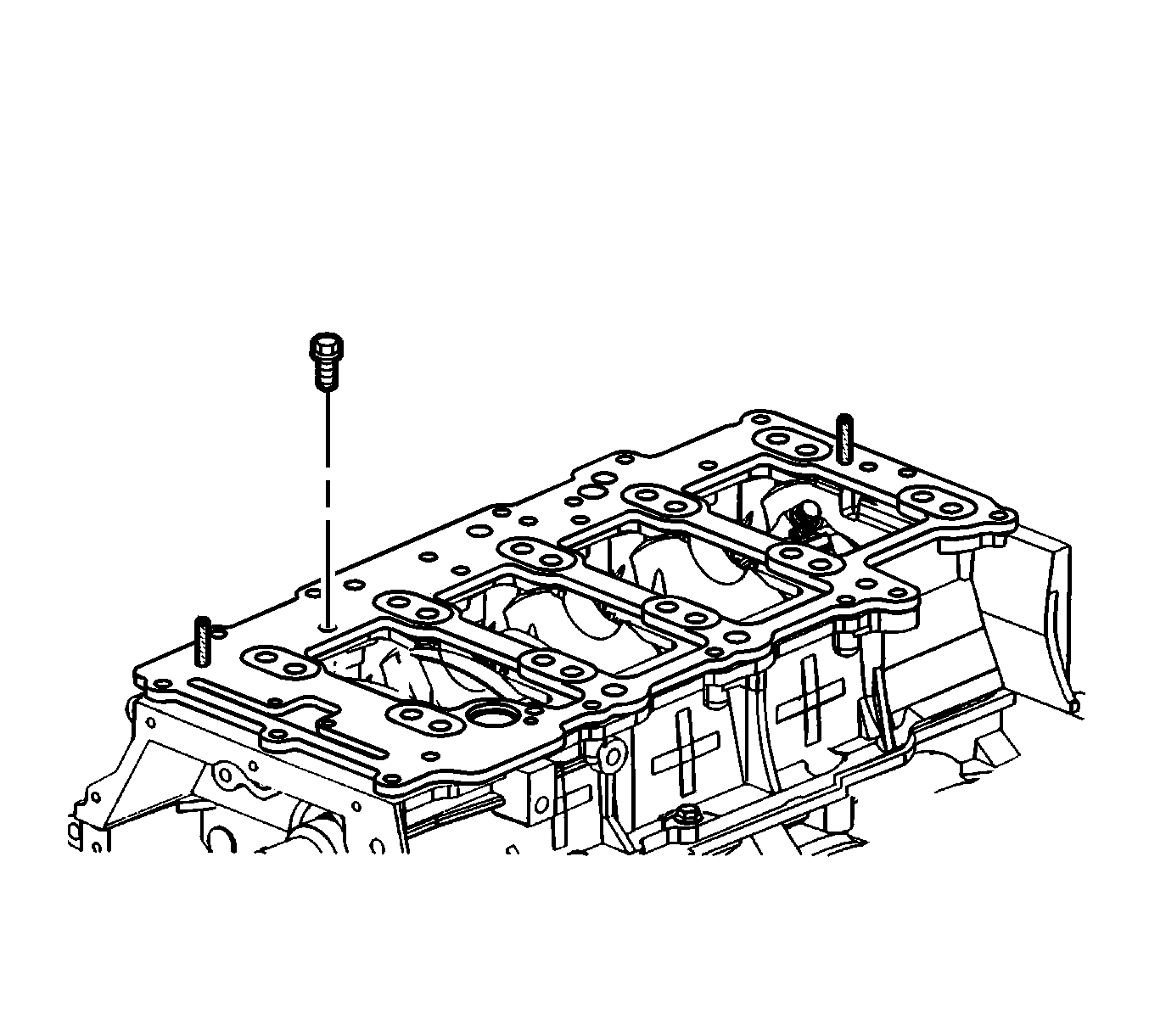
- Install the oil distribution plate bolts.
- Using a small long blade screwdriver clean out any sealant in the oil drain back passages.
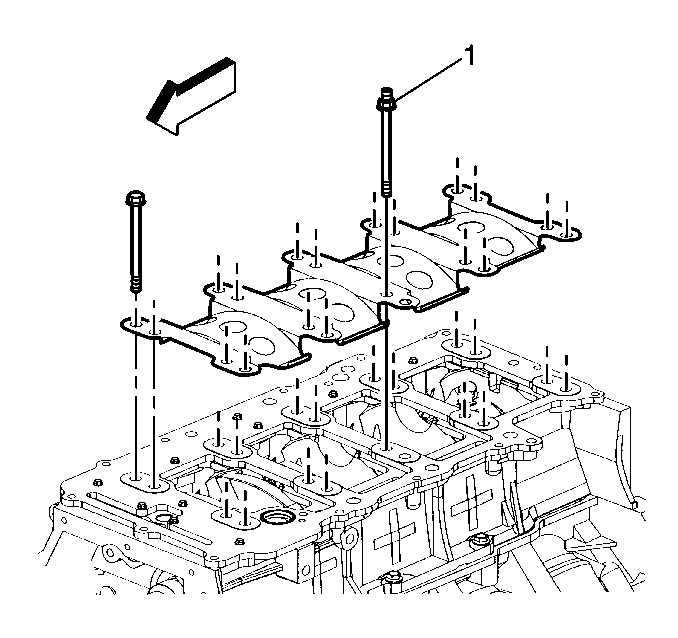
- Install the crankshaft oil scraper plate.
- Install the main bearing bolts. Ensure the stud-head bolt (1) used for the oil suction tube support bracket is placed in the proper position.
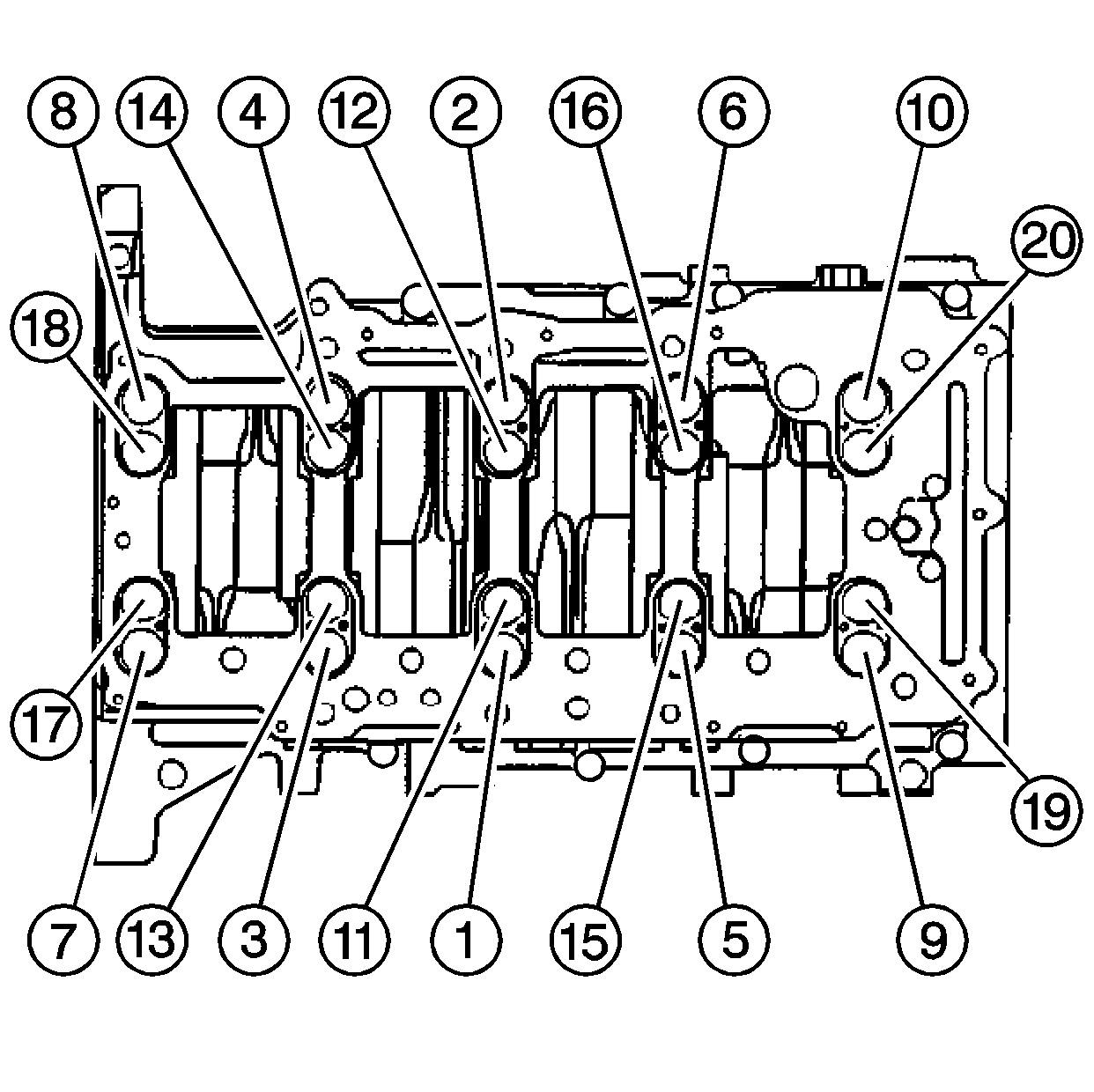
- Tighten the main bearing bolts in the proper sequence.
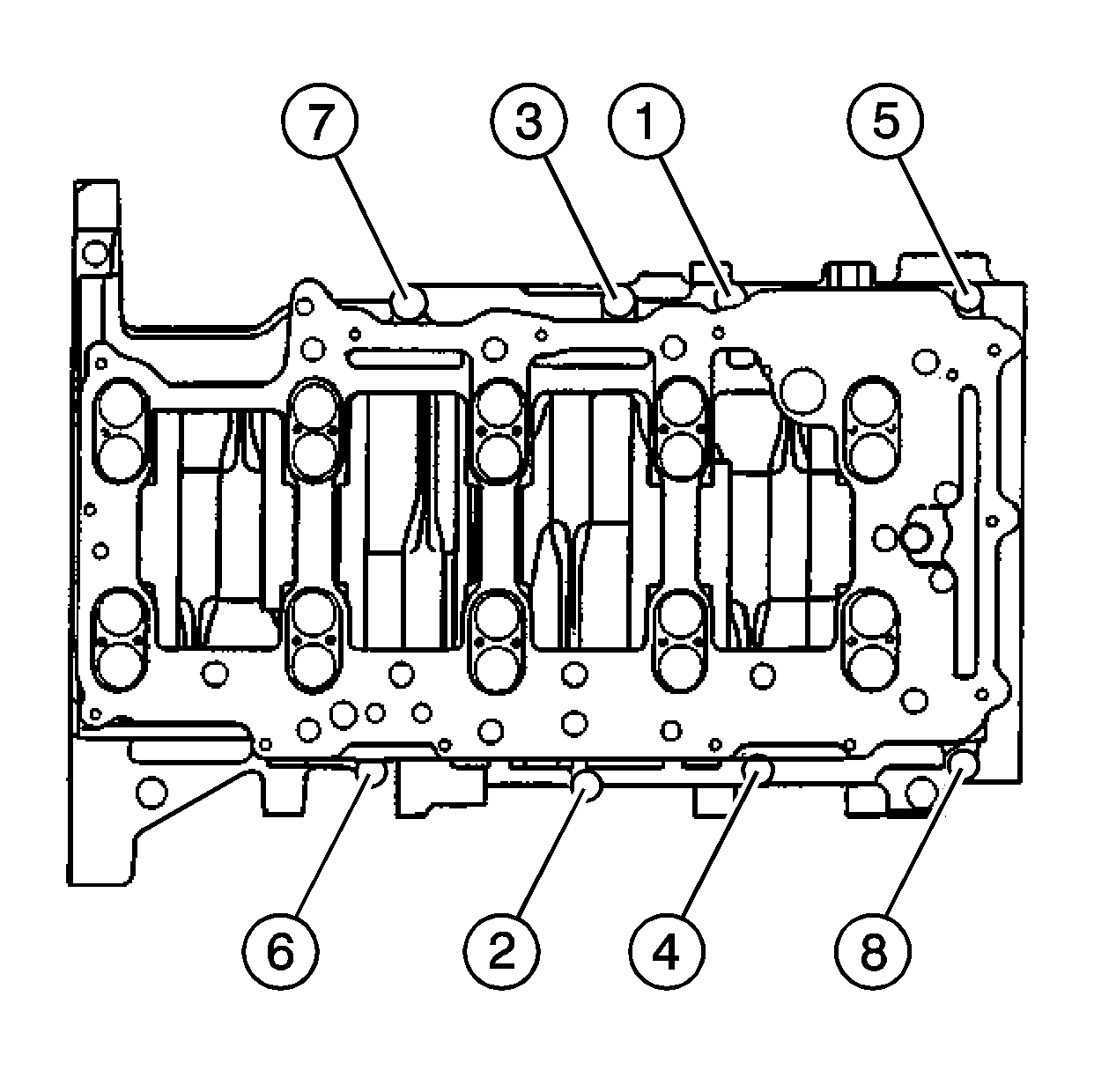
- Tighten the crankcase perimeter bolts in sequence shown.
- Using a small long blade screwdriver verify that the threaded holes for the oil pan bolts and the oil drain back passages are clear of sealant.
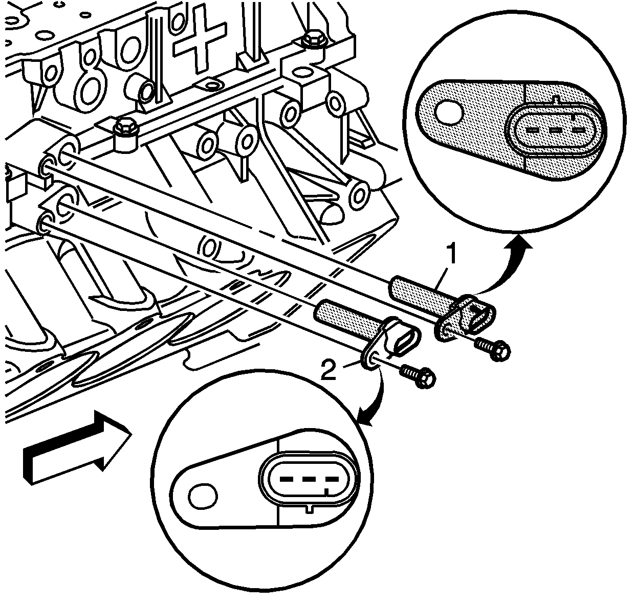
- Install the crankshaft position sensors. Ensure the crankshaft position sensor with the darker colored connector end (1) is installed in the lower crankcase and crankshaft position sensor with the lighter colored connector end (2) is installed in the block.
- Install the crankshaft position sensor bolts.
- Using the J 39946 rotate the crankshaft until the number one piston is at top dead center (TDC) and the crankshaft key way is approximately at the 7 o'clock position.
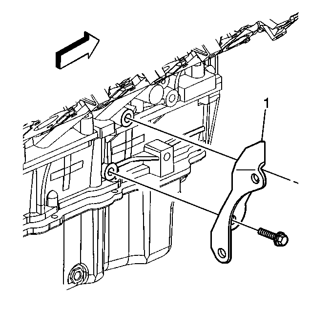
- Place the transaxle brace (1) in position on the cylinder block.
- Install the transaxle brace retaining bolts.
Important: Ensure components being sealed with RTV are assembled within 20 minutes. Components assembled after the RTV has skinned-over, approximately 20 minutes, will not seal properly.
Important: Ensure components being sealed with RTV are assembled within 20 minutes. Components assembled after the RTV has skinned-over, approximately 20 minutes, will not seal properly.
Notice: Use the correct fastener in the correct location. Replacement fasteners must be the correct part number for that application. Fasteners requiring replacement or fasteners requiring the use of thread locking compound or sealant are identified in the service procedure. Do not use paints, lubricants, or corrosion inhibitors on fasteners or fastener joint surfaces unless specified. These coatings affect fastener torque and joint clamping force and may damage the fastener. Use the correct tightening sequence and specifications when installing fasteners in order to avoid damage to parts and systems.
Tighten
Tighten the oil distribution plate bolts to 10 N·m (89 lb in).
| 19.1. | First Pass |
Tighten
Tighten the main bearing bolts (1-20) to 20 N·m (15 lb ft ) in the proper sequence.
| 19.2. | Final Pass |
Tighten
Tighten the main bearing bolts (1-20) an additional 65 degrees in the proper sequence using the
J 45059
.
Tighten
Tighten the crankcase perimeter bolts to 30 N·m (22 lb ft).
Tighten
Tighten the crankshaft position sensor bolts to 10 N·m (89 lb in).
Tighten
Tighten the transaxle brace retaining bolts to 50 N·m (37 lb ft).
