Tools Required
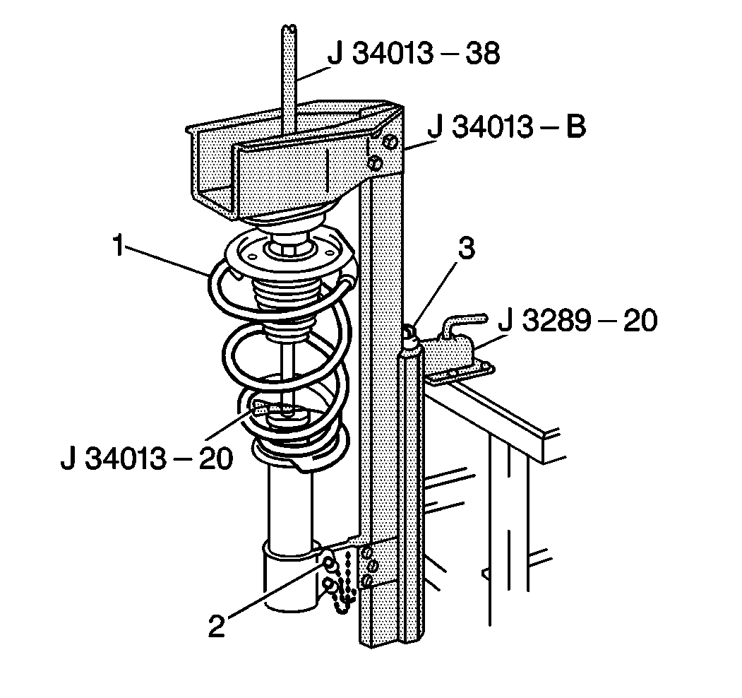
| • | J 34013-B Strut Compressor |
| • | J 34013-38 Alignment Rod |
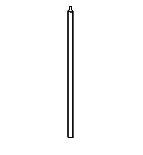
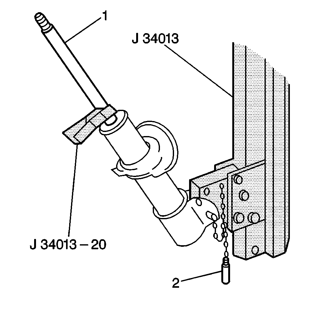
| • | J 34013-20 Damper Rod Clamp |
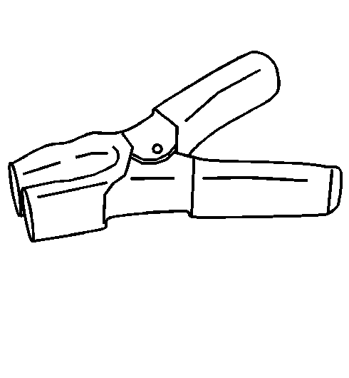
Removal Procedure
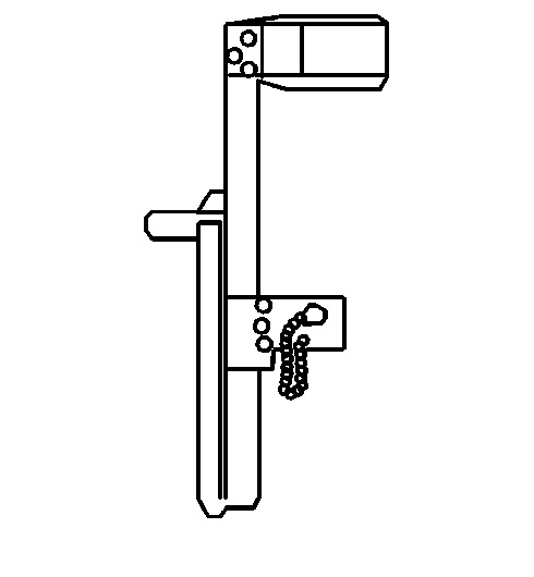
- Install J 34013-B to J 34013-20 if a wall mounted version is not available.
- Install the strut (1) into the J 34013-B .
- Turn the compressor forcing screw (3) until the spring compresses slightly.
- Use a socket (3) in order to hold the strut shaft from turning.
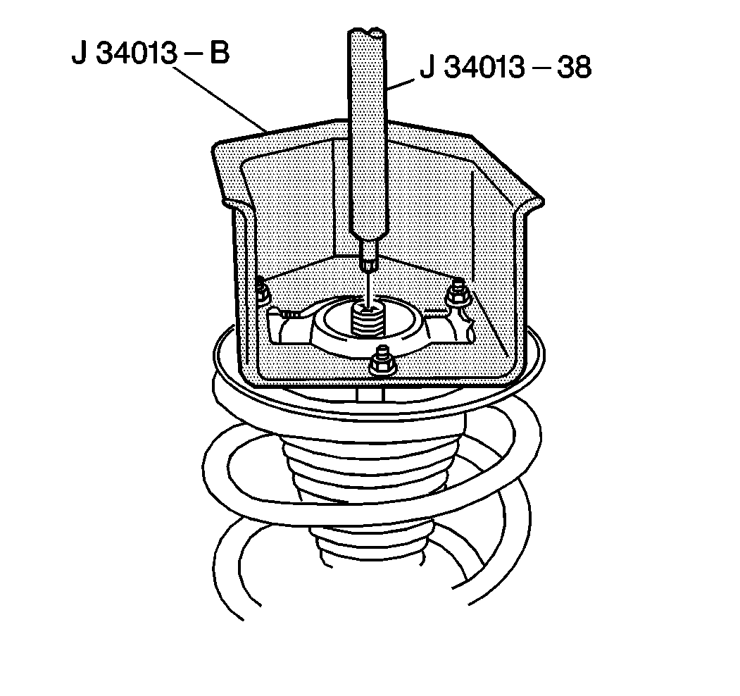
- Install the J 34013-38 in order to help guide the strut shaft out of the assembly.
- Loosen the compressor screw (3) while guiding the strut shaft (1) out of the assembly. Continue loosening the compressor screw until the strut and the spring may be removed.
Notice: Care should be taken to avoid chipping or cracking the spring coating when handling the front suspension coil spring. Failure to observe this notice may result in spring breakage.
Important: Remove the strut from the vehicle in order to perform this procedure. Refer to Strut Assembly Replacement .
| • | Tighten the nuts (2) flush with the strut compressor. |
| • | Install the locking pins (4) through the strut. |
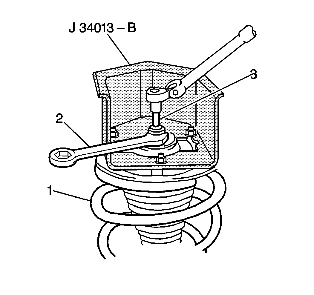
Remove the 24 mm strut shaft nut using a 24 mm wrench (2).
Notice: Care should be taken to avoid chipping or cracking the spring coating when handling the front suspension coil spring. Failure to observe this notice may result in spring breakage.
Installation Procedure
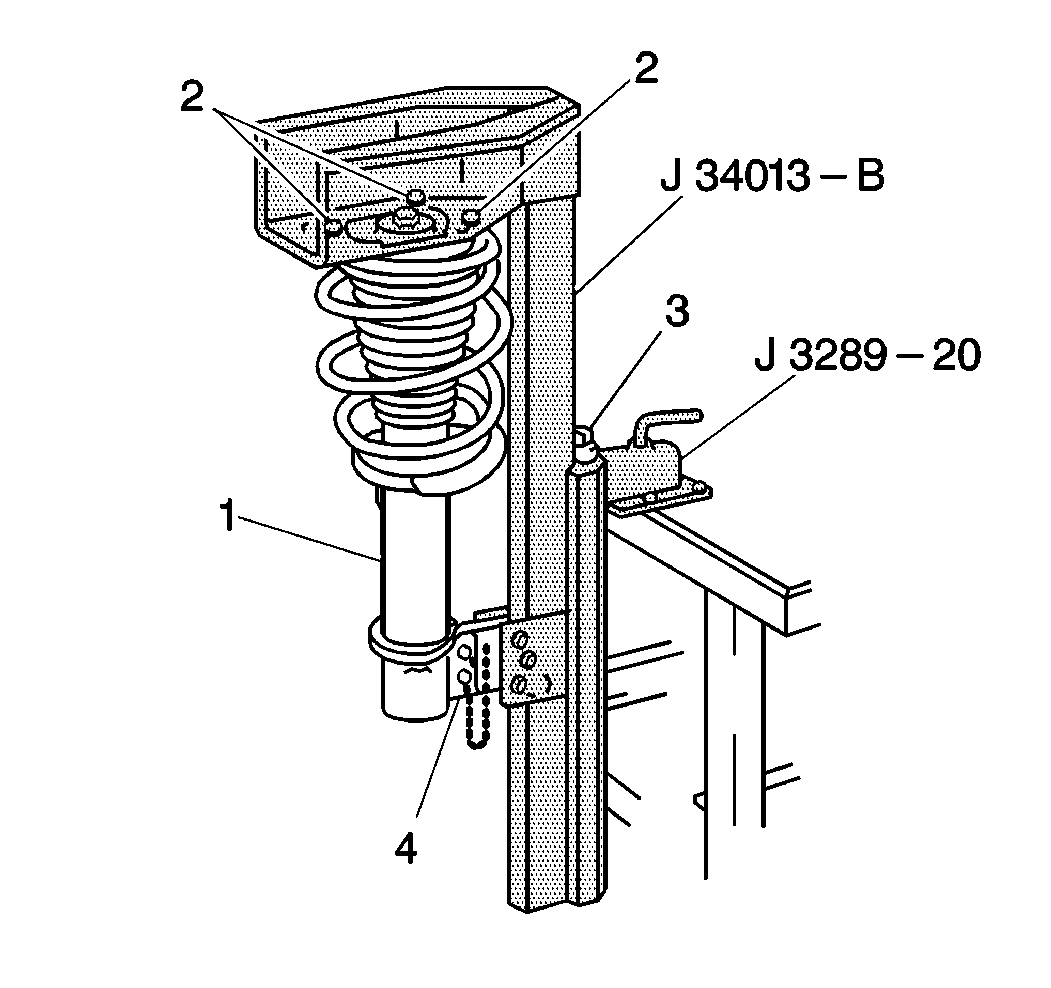
- Install the strut in the J 34013-B with the J 34013-20 clamped on the strut shaft (1) in the strut compressor.
- Install the spring over the strut in the correct position.
- Move the assembly upright in the strut compressor.
- Install the upper locking pin (2).
- Install the rod J 34013-38 into the strut guide strut shaft.
- Start turning the compressor screw clockwise on the J 34013-B , while guiding the J 34013-38 to the center strut shaft in the assembly.
- Continue to turn the compressor forcing screw (3) on the strut compressor until the strut shaft threads are visible through the top of the strut assembly.
- Install the washer and the nut.
- Remove the clamp J 34013-20 from the strut shaft.
- Remove the strut from the strut compressor.
Important:
• Ensure that the flat on the upper spring seat faces out from the
centerline of the vehicle. When you mount the spring seat in the strut compressor,
ensure that the spring seat faces in the same direction as the steering
knuckle mounting flange. • If the bearing had been removed from the upper spring seat, install
the bearing into the upper spring seat in the same orientation as it had been.
Also, install the bearing in the spring seat before attaching to the
strut mount.
Notice: Use the correct fastener in the correct location. Replacement fasteners must be the correct part number for that application. Fasteners requiring replacement or fasteners requiring the use of thread locking compound or sealant are identified in the service procedure. Do not use paints, lubricants, or corrosion inhibitors on fasteners or fastener joint surfaces unless specified. These coatings affect fastener torque and joint clamping force and may damage the fastener. Use the correct tightening sequence and specifications when installing fasteners in order to avoid damage to parts and systems.
Tighten
Tighten the strut mount nut to 75 N·m (55 lb ft)
while holding the strut shaft with the socket.
