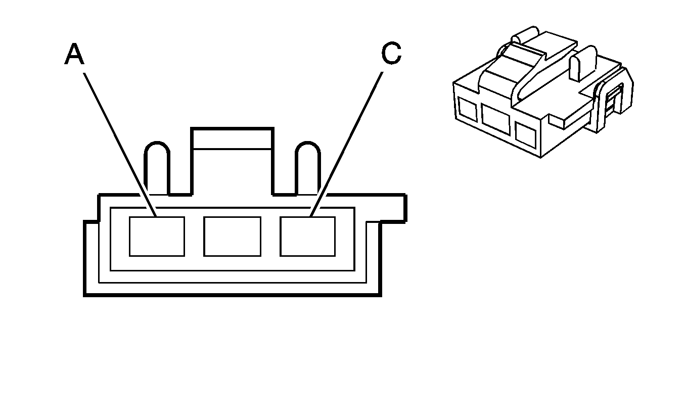
| Table 1: | Power Antenna Relay C1 |
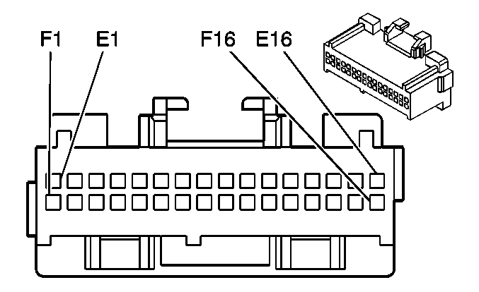
| Table 2: | Radio |
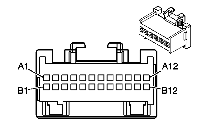
| Table 3: | Radio Interface Module (RIM) C1 |
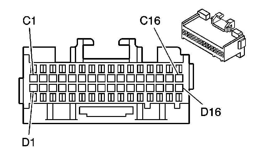
| Table 4: | Radio Interface Module (RIM) C2 |
| Table 5: | Remote Playback Device - CD Changer |
| Table 6: | Speaker - LF Door (w/UQ4) |
| Table 7: | Speaker - LF Door (w/o UQ4) |
| Table 8: | Speaker - LR (w/UQ4) |
| Table 9: | Speaker - LR (w/o UQ4) |
| Table 10: | Speaker - RF Door (w/UQ4) |
| Table 11: | Speaker - RF Door (w/o UQ4) |
| Table 12: | Speaker - RR (w/UQ4) |
| Table 13: | Speaker - RR (w/o UQ4) |
| Table 14: | Steering Wheel Controls -- Left-Steering Wheels Controls Harness Side |
| |||||||
|---|---|---|---|---|---|---|---|
Connector Part Information |
| ||||||
Pin | Wire Color | Circuit No. | Function | ||||
A | ORN | 2140 | Battery Positive Voltage | ||||
B | DK GRN | 145 | Antenna Relay Coil Supply Voltage | ||||
C | BLK | 1250 | Ground | ||||
| |||||||
|---|---|---|---|---|---|---|---|
Connector Part Information |
| ||||||
Pin | Wire Color | Circuit No. | Function | ||||
E1 | DK GRN | 835 | Entertainment and Comfort Serial Data | ||||
E2-E4 | -- | -- | Not Used | ||||
E5 | GRY | 8 | Instrument Panel Lamp Supply Voltage - 1 | ||||
E6 | PPL | 1807 | Class 2 Serial Data | ||||
E7 | LT BLU/BLK | 659 | Cellular Telephone Voice Low Reference | ||||
E8 | DK BLU | 658 | Cellular Telephone Voice Signal | ||||
E9 | BLK/WHT | 372 | Remote Radio Audio Output (-) | ||||
E10 | BRN/WHT | 367 | Remote Radio Left Audio Signal | ||||
E11 | DK GRN/WHT | 368 | Remote Radio Right Audio Signal | ||||
E12 | BRN | 199 | Left Rear Speaker Output (+) (with UW6) | ||||
TAN | 511 | Left Front Low Level Audio Signal (with UQ4 or UQ6) | |||||
E13 | YEL | 116 | Left Rear Speaker Output (-) (with UW6) | ||||
DK GRN | 1947 | Left Front Low Level Audio Signal (-) (with UQ4 or UQ6) | |||||
E14 | DK GRN | 117 | Right Front Speaker Output (-) (with UW6) | ||||
BARE | 1782 | Drain Wire (with UQ4 or UQ6) | |||||
E15 | LT GRN | 200 | Right Front Speaker Output (+) (with UW6) | ||||
BARE | 1782 | Drain Wire (with UQ4 or UQ6) | |||||
E16 | BLK | 1051 | Ground | ||||
F1 | ORN | 40 | Battery Positive Voltage | ||||
F2 | -- | -- | Not Used | ||||
F3 | DK GRN | 145 | Antenna Relay Coil Supply Voltage | ||||
F4 | -- | -- | Not Used | ||||
F5 | BLK | 1250 | Ground | ||||
F6 | PPL | 1807 | Class 2 Serial Data | ||||
F7-F10 | -- | -- | Not Used | ||||
F11 | BARE | 1782 | Drain Wire (with UQ4 or UQ6) | ||||
F12 | TAN | 201 | Left Front Speaker Output (+) (with UW6) | ||||
PPL/WHT | 652 | Chime Module Bit 2 Signal (with UQ4 or UQ6) | |||||
F13 | GRY | 118 | Left Front Speaker Output (-) (with UW6) | ||||
DK BLU/WHT | 653 | Chime Module Bit 1 Signal (with UQ4 or UQ6) | |||||
F14 | LT BLU | 115 | Right Rear Speaker Output (-) (with UW6) | ||||
LT GRN/BLK | 1948 | Right Front Low Level Audio Signal (-) (with UQ4 or UQ6) | |||||
F15 | DK BLU | 46 | Right Rear Speaker Output (+) (with UW6) | ||||
LT GRN | 512 | Right Front Low Level Audio Signal (with UQ4 or UQ6) | |||||
F16 | -- | -- | Not Used | ||||
| |||||||
|---|---|---|---|---|---|---|---|
Connector Part Information |
| ||||||
Pin | Wire Color | Circuit No. | Function | ||||
A1 | BLK | 1051 | Ground | ||||
A2 | BLK | 1946 | Right Rear Low Level Audio Signal (-) | ||||
A3 | DK BLU | 546 | Right Rear Low Level Audio Signal | ||||
A4 | BARE | 1792 | Drain Wire | ||||
A5 | BRN/WHT | 1999 | Left Rear Low Level Audio Signal (-) | ||||
A6 | BRN | 599 | Left Rear Low Level Audio Signal | ||||
A7 | BARE | 1792 | Drain Wire | ||||
A8 | LT GRN/BLK | 1948 | Right Front Low Level Audio Signal (-) | ||||
A9 | BLK | 1875 | Right Front Speaker Output (+) | ||||
A10 | BARE | 1792 | Drain Wire | ||||
A11 | DK GRN | 1947 | Left Front Low Level Audio Signal (-) | ||||
A12 | LT BLU | 1874 | Left Front Speaker Output (+) | ||||
B1 | ORN | 40 | Battery Positive Voltage | ||||
B2 | PPL | 1807 | Class 2 Serial Data | ||||
B3 | PPL | 1807 | Class 2 Serial Data | ||||
B4 | DK GRN | 1947 | Left Front Low Level Audio Signal (-) | ||||
B5 | TAN | 511 | Left Front Low Level Audio Signal | ||||
B6 | LT GRN/BLK | 1948 | Right Front Low Level Audio Signal (-) | ||||
B7 | LT GRN | 512 | Right Front Low Level Audio Signal | ||||
B8 | BRN/WHT | 367 | Remote Radio Left Audio Signal | ||||
B9 | BLK/WHT | 372 | Remote Radio Audio Output (-) | ||||
B10 | -- | -- | Not Used | ||||
B11 | DK GRN/WHT | 368 | Remote Radio Right Audio Signal | ||||
B12 | BARE | 1792 | Drain Wire | ||||
| |||||||
|---|---|---|---|---|---|---|---|
Connector Part Information |
| ||||||
Pin | Wire Color | Circuit No. | Function | ||||
C1-C16 | -- | -- | Not Used | ||||
D1 | -- | -- | Not Used | ||||
D2 | ORN | 360 | Amplifier Feed | ||||
D3-D11 | -- | -- | Not Used | ||||
D12 | DK BLU/WHT | 653 | Chime Module Bit 1 | ||||
D13 | PPL/WHT | 652 | Chime Module Bit 2 | ||||
D14 | LT BLU/BLK | 659 | Cellular Telephone Voice Low Reference-not present on Export | ||||
D15 | DK BLU | 658 | Cellular Telephone Voice Signal-not present on Export | ||||
D16 | -- | -- | Not Used | ||||
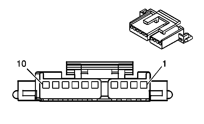
| |||||||
|---|---|---|---|---|---|---|---|
Connector Part Information |
| ||||||
Pin | Wire Color | Circuit No. | Function | ||||
1 | BRN/WHT | 367 | Remote Radio Left Audio Signal | ||||
2 | DK GRN/WHT | 368 | Remote Radio Right Audio Signal | ||||
3 | BLK/WHT | 372 | Remote Radio Audio Output (-) | ||||
4 | BARE | 1792 | Drain Wire | ||||
5 | ORN | 2640 | Battery Positive Voltage | ||||
6 | -- | -- | Not Used | ||||
7 | BLK | 1051 | Ground | ||||
8-9 | -- | -- | Not Used | ||||
10 | DK GRN | 835 | Entertainment and Comfort Serial Data | ||||
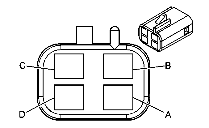
| |||||||
|---|---|---|---|---|---|---|---|
Connector Part Information |
| ||||||
Pin | Wire Color | Circuit No. | Function | ||||
A | ORN | 1950 | Left Front Speaker Amplifier Supply Voltage | ||||
B | DK GRN | 1947 | Left Front Low Level Audio Signal | ||||
C | LT BLU | 1874 | Left Front Speaker Output (+) | ||||
D | BLK | 1051 | Ground | ||||
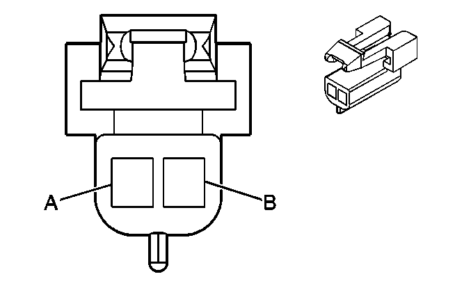
| |||||||
|---|---|---|---|---|---|---|---|
Connector Part Information |
| ||||||
Pin | Wire Color | Circuit No. | Function | ||||
A | GRY | 118 | Left Front Speaker Output (-) | ||||
B | TAN | 201 | Left Front Speaker Output (+) | ||||
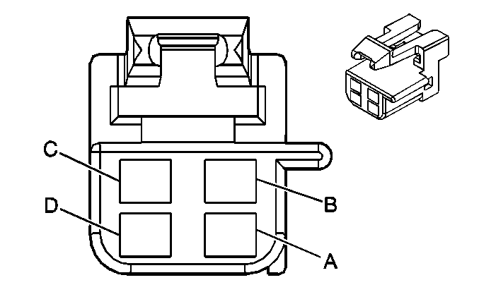
| |||||||
|---|---|---|---|---|---|---|---|
Connector Part Information |
| ||||||
Pin | Wire Color | Circuit No. | Function | ||||
A | ORN | 19501 | Left Rear Speaker Amplifier Supply Voltage | ||||
B | BRN/WHT | 1999 | Left Rear Low Level Audio Signal (-) | ||||
C | BRN | 599 | Left Rear Low Level Audio Signal | ||||
D | BLK | 1051 | Ground | ||||

| |||||||
|---|---|---|---|---|---|---|---|
Connector Part Information |
| ||||||
Pin | Wire Color | Circuit No. | Function | ||||
A | YEL | 116 | Left Rear Speaker Output (-) | ||||
B | BRN | 199 | Left Rear Speaker Output (+) | ||||

| |||||||
|---|---|---|---|---|---|---|---|
Connector Part Information |
| ||||||
Pin | Wire Color | Circuit No. | Function | ||||
A | ORN/BLK | 1951 | Right Front Speaker Amplifier Supply Voltage | ||||
B | LT GRN/BLK | 1948 | Right Front Low Level Audio Signal (-) | ||||
C | BLK | 1875 | Right Front Speaker Output (+) | ||||
D | BLK | 1051 | Ground | ||||

| |||||||
|---|---|---|---|---|---|---|---|
Connector Part Information |
| ||||||
Pin | Wire Color | Circuit No. | Function | ||||
A | DK GRN | 117 | Right Front Speaker Output (-) | ||||
B | LT GRN | 200 | Right Front Speaker Output (+) | ||||

| |||||||
|---|---|---|---|---|---|---|---|
Connector Part Information |
| ||||||
Pin | Wire Color | Circuit No. | Function | ||||
A | ORN/BLK | 1951 | Right Rear Speaker Amplifier Supply Voltage | ||||
B | BLK | 1946 | Right Rear Low Level Audio Signal (-) | ||||
C | DK BLU | 546 | Right Rear Low Level Audio Signal | ||||
D | BLK | 1051 | Ground | ||||

| |||||||
|---|---|---|---|---|---|---|---|
Connector Part Information |
| ||||||
Pin | Wire Color | Circuit No. | Function | ||||
A | LT BLU | 115 | Right Rear Speaker Output (-) | ||||
B | DK BLU | 46 | Right Rear Speaker Output (+) | ||||
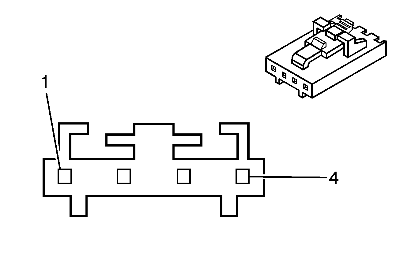
| |||||||
|---|---|---|---|---|---|---|---|
Connector Part Information |
| ||||||
Pin | Wire Color | Circuit No. | Function | ||||
1 | BLU | -- | Steering Wheel Controls Signal | ||||
2 | YEL | -- | Steering Wheel Controls Signal | ||||
3 | WHT | -- | Ground | ||||
4 | GRN | -- | Instrument Panel Lamp Supply Voltage - 1 | ||||
