Bumpers
The front bumper assembly consists of an impact bar that is covered
with a polyurethane RIM fascia. The RIM fascia is supported by fascia guides
at each side. The bumper is attached to the body through left and right
2-stage energy absorbing units.
The Eldorado rear bumper design is the same as the front bumper. The
rear bumper is made of a polyurethane RIM material. The impact bar is attached
to the body through left and right single-stage energy absorbing units.
The lower fascia is attached to the impact bar and the rear wheelhouse
areas. The lower fascia uses the body side moldings, brackets and the rear
side marker lamps for support.
Energy Absorbing Units
The bumpers are designed
so that the vehicle can withstand a collision with a fixed barrier at 8 km/h
(5 mph) with limited damage. After absorbing the energy of the collision,
the energy absorbing (EA) units restore the bumper to the original position.
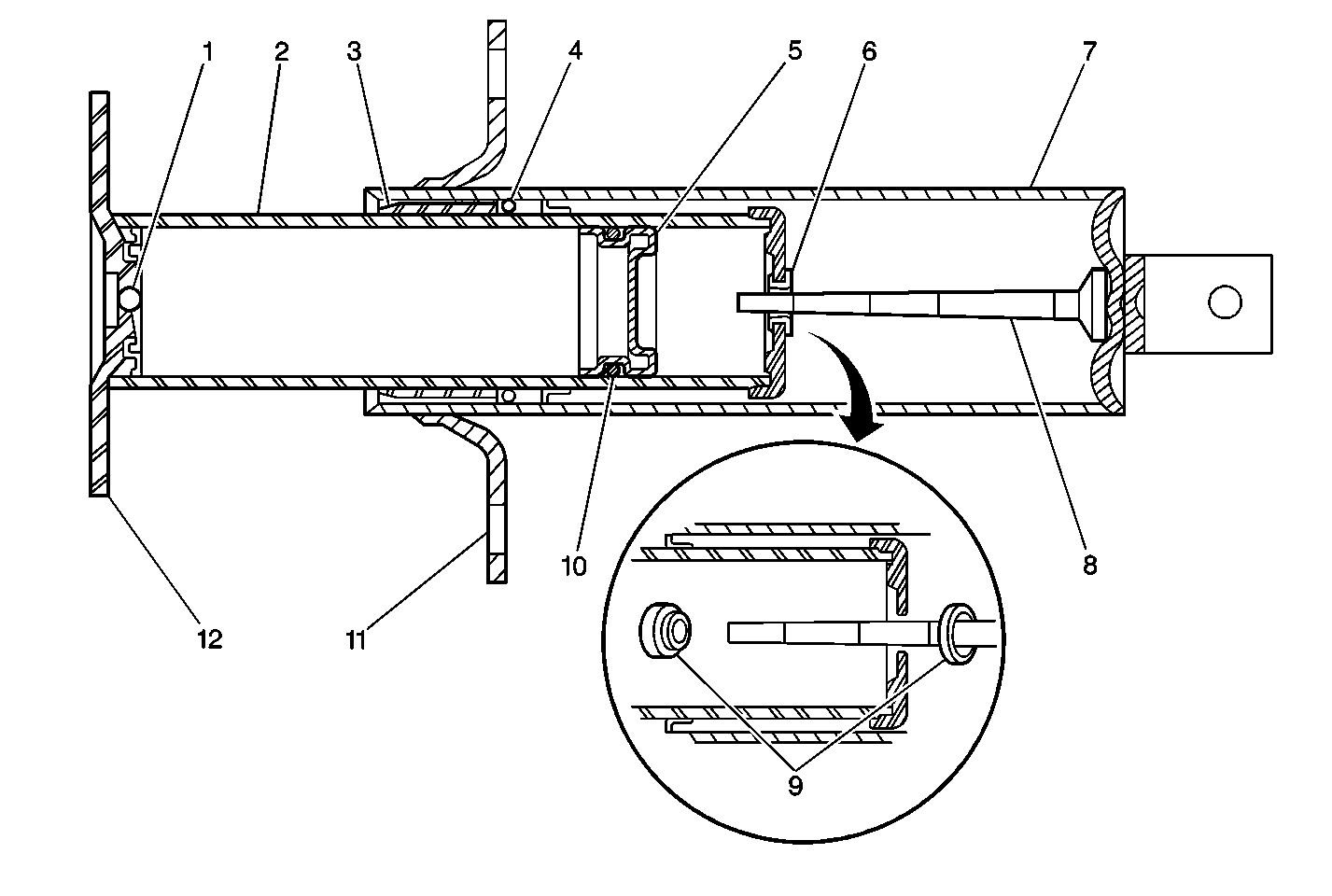
The EA device consists of the following 2 main sub-assemblies:
| • | The cylinder tube assembly |
| • | The piston tube assembly |
The cylinder tube assembly is filled with a hydraulic fluid. The cylinder
tube assembly consists of the following components:
| • | A rear mounting bracket |
The piston tube assembly is filled with an inert gas under pressure
. The piston tube assembly consists of the following components:
| • | A breakaway orifice (9) |
The orifice (9) replaces the calibrated orifice that is used
in conventional single-stage energy absorbers. This plug provides the 2-stage
action.
In vehicle impacts below 8 km/h (5 mph), the 2-stage
energy absorber acts like a conventional single-stage absorber. As the energy
absorber collapses, the hydraulic fluid in the cylinder tube (7)
is forced into the piston tube (2) through an orifice in the brass
blowout plug. The metering pin (8) controls the rate at which the
hydraulic fluid passes through the brass plug into the piston tube (2).
The controlled movement of the hydraulic fluid provides the energy absorbing
action.
In vehicle impacts from 8 km/h (5 mph) to
48.2 km/h (30 mph), the brass plug is designed to blow off of
the bras plug seat. This provides the second-stage action. With the plug
dislodged, the hydraulic fluid passageway becomes greatly enlarged. The
larger opening allows the fluid to move rapidly from the cylinder tube (7)
to the piston tube (2). This provides the energy absorption at
greater impulses. Due to the one time (non-repeatable) nature of the 2-stage
action, examine the energy absorber after a collision in order to verify
the 2-stage operation. Replace the unit after a high-speed impact.
In either stage of absorber action, the hydraulic fluid
that is forced from the cylinder tube (7) into the piston tube (2)
displaces the floating piston (5). This compresses the inert gas
behind the floating piston (5). After impact, the pressure of the
compressed gas behind the floating piston (5) forces the hydraulic
fluid back into the cylinder tube (7) assembly. This extends the
energy absorber to the normal position.
