Removal Procedure
- Open the hood.
- Disconnect the negative battery cable from the battery. Refer to Battery Negative Cable Disconnection and Connection in Engine Electrical.
- Disconnect the washer solvent hose.
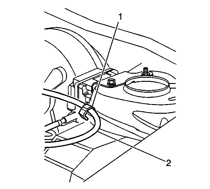
- Unclip the retention clip (1) on the strut tower securing the cruise control cable (2).
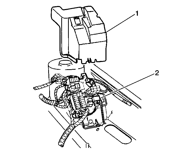
- Disconnect the upper and lower snap tabs from the multi-use relay and fuse bracket cover.
- Remove the multi-use relay and fuse bracket cover (1).
- Remove the positive battery cable fastener from the underhood multi-use relay and fuse center bracket.
- Position the positive battery cable away from the multi-use relay and fuse center bracket.
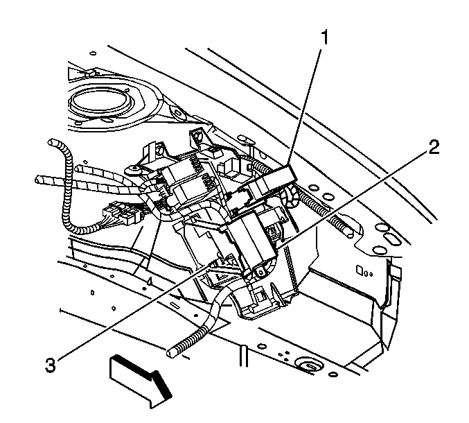
- Unclip the cover retaining clips from the 8-way maxi fuse (2) and 8-way relay centers (1) and remove.
- Unclip the cover retaining clips from the 12-way mini fuse and 2-way micro relay centers and remove.
- Unclip the cover retaining the 6-way maxi fuse center and remove.
- Remove the following components from the multi-use relay and fuse bracket assembly:
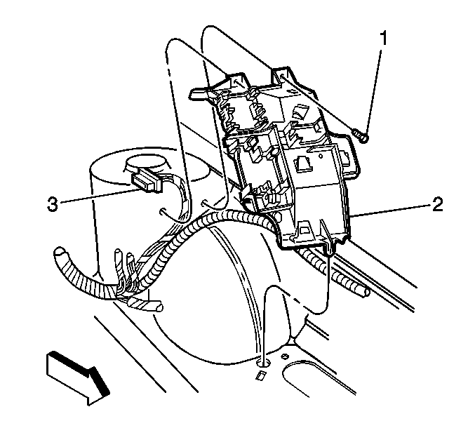
- Remove the two fasteners (1) from the multi-use relay and fuse center bracket (2).
- Remove the multi-use relay and fuse center bracket (2) from the vehicle.
Notice: Note the correct routing of the electrical wiring. Failure to reinstall the wiring properly could result in damage to the wiring.
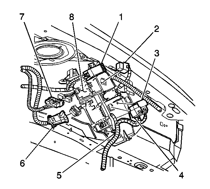
| • | The 6-way micro fuse center (1) |
| • | The inadvertent power relay (2) |
| • | The starter enable relay (3) |
| • | The ignition relay (4) |
| • | Disconnect the retainer for the electrical harness (5) |
Installation Procedure
- Snap the lower rosebud on the bracket into the hole in the rail.
- Position the multi-use relay and fuse center bracket (2) to the strut tower.
- Install the multi-use relay and fuse center bracket fasteners (1).
- Install the following components to the multi-use relay and fuse bracket assembly:
- Install the cover for the 6-way maxi fuse center .
- Install the cover for the 12-way mini fuse and 2-way micro relay centers
- Install the cover for the 8-way maxi fuse (2) and 8-way relay centers (1).
- Position the positive battery cable to the stud (3) on the multi-use relay and fuse center bracket.
- Install the positive battery cable fastener.
- Tuck the engine harness body main electrical connections under the multi-use relay and fuse bracket.
- Position the multi-use relay and fuse bracket cover (1) to the bracket.
- Install the upper and lower retainer tabs into the bracket in order to secure the cover. Press into place until fully seated.
- Connect the washer solvent hose connector.
- Secure the cruise control cable (2) to the retention clip (1) located on the left strut tower.
- Connect the negative battery cable. Refer to Battery Negative Cable Disconnection and Connection in Engine Electrical.
- Close the hood.

Important: Ensure the body main electrical harness connector (3) is located between the two mounting holes in the strut tower and above the multi-use relay and fuse center bracket.
Notice: Use the correct fastener in the correct location. Replacement fasteners must be the correct part number for that application. Fasteners requiring replacement or fasteners requiring the use of thread locking compound or sealant are identified in the service procedure. Do not use paints, lubricants, or corrosion inhibitors on fasteners or fastener joint surfaces unless specified. These coatings affect fastener torque and joint clamping force and may damage the fastener. Use the correct tightening sequence and specifications when installing fasteners in order to avoid damage to parts and systems.
Tighten
Tighten the 2 fasteners (1) to 9 N·m (80 lb in).

| • | Secure the retainer for the electrical harness (5) |
| • | Install the ignition relay (4) |
| • | Install the starter enable relay (3) |
| • | Install the inadvertent power relay (2) |
| • | Install the 6-way micro fuse center (1) |

Tighten
Tighten the fastener to 11 N·m (97 lb in).


