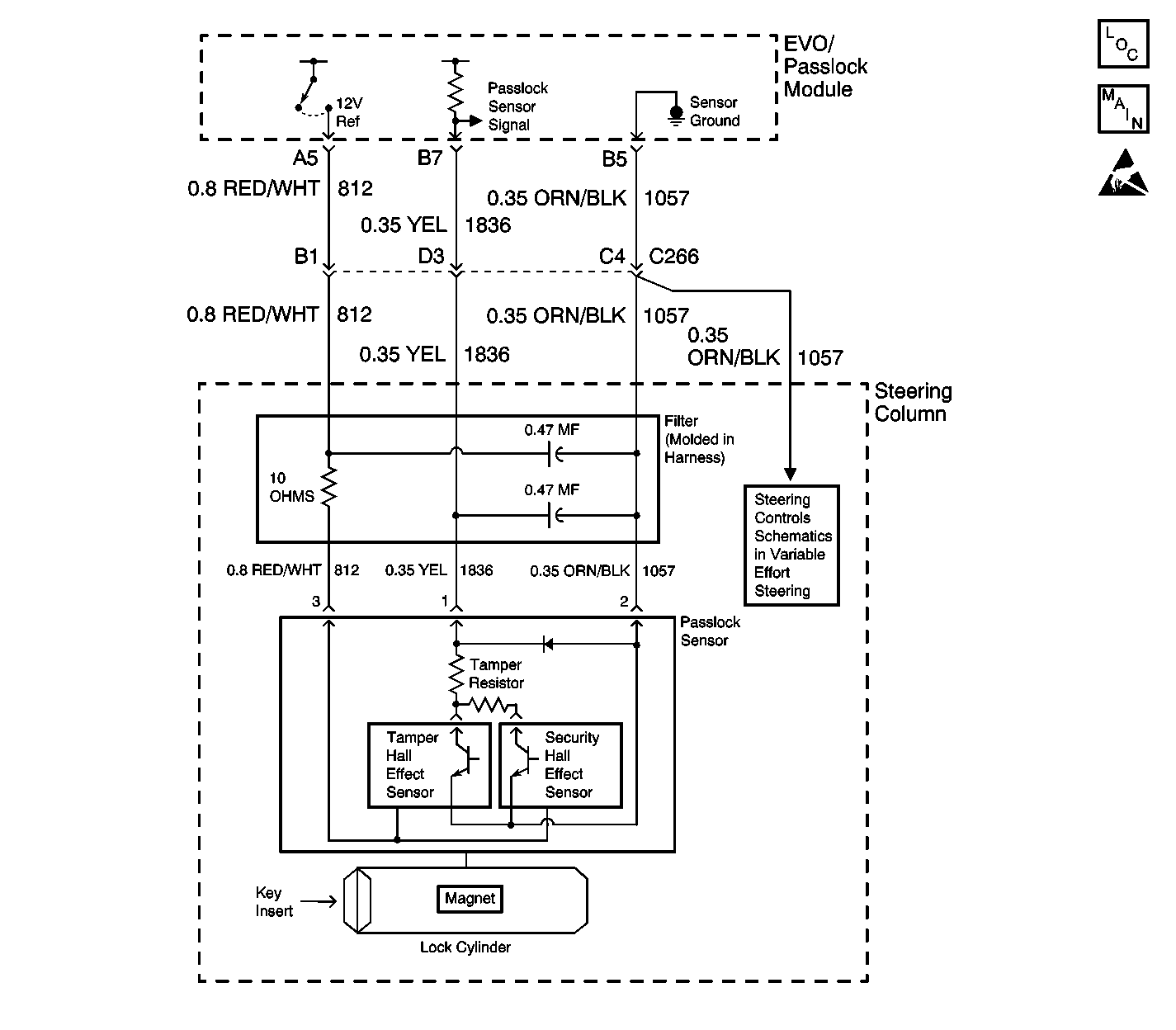
Circuit Description
The EVO/Passlock™ module supplies power to the Passlock™ sensor on CKT 812.
When the Passlock™ sensor is powered and the ignition switch is rotated to the crank position, the hall effect security sensor will latch holding an internal code value. The EVO/Passlock™ module will compare this code to the value the EVO/Passlock™ module measured in the last ignition cycle. If the latched value is the same as the last ignition cycle value the test has passed. When the ignition switch is switched to the OFF position, the sensor is no longer powered and resets the sensor latch circuit.
In the next ignition cycle, the Passlock™ sensor waits for an ignition switch crank input and verifies the sensor code. The Passlock™ sensor compares the input to the last recognized code.
If the Passlock™ sensor power is shorted to battery voltage, the sensor will not reset. This renders the Passlock™ system ineffective.
Conditions for Setting the DTC
| • | The ignition switch is OFF. |
| • | The EVO/Passlock™ module turns the sensor power, approximately 12 volts, OFF when the ignition switch is turned OFF. If the Passlock™ sensor power has 12 volts applied after the ignition switch is turned OFF, DTC B2948 is set. |
Action Taken When the DTC Sets
The vehicle will continue to start and run with the security telltale ON.
Conditions for Clearing the DTC
| • | The DTC will clear after an ignition cycle has occurred without the fault. |
| • | EVO/Passlock™ module history codes will be cleared after 100 ignition cycles with no current codes active. |
| • | Using a scan tool. |
Diagnostic Aids
| • | When replacing the Passlock™ sensor, all the sensor components lock, sensor, filter, and harness are included as a replacement part and must be replaced. |
| • | Use the scan tool in order to inspect the Passlock™ data voltage and the Passlock™ code. |
| • | Perform a visual inspection of the wiring and the connectors. |
| • | Inspect the Passlock™ sensor harness for an intermittent or a short to battery. Refer to Testing for Intermittent Conditions and Poor Connections in Wiring Systems. |
Test Description
The numbers below refer to the numbers on the diagnostic table.
-
This step isolates the short to battery between the EVO/Passlock™ module and the harness.
-
This step isolates the short to battery between the Passlock sensor and the harness.
Step | Action | Value(s) | Yes | No | ||||||||||||||||||||||||
|---|---|---|---|---|---|---|---|---|---|---|---|---|---|---|---|---|---|---|---|---|---|---|---|---|---|---|---|---|
1 | Did you perform the VTD Diagnostic System Check? | -- | Go to Step 2 | |||||||||||||||||||||||||
Is the voltage within the specified range? | 9-16 volts | Go to Step 3 | Go to Step 6 | |||||||||||||||||||||||||
Is the voltage within the specified range? | 9-16 volts | Go to Step 4 | Go to Step 5 | |||||||||||||||||||||||||
4 | Repair the short to battery in CKT 812. Is the repair complete? | -- | -- | |||||||||||||||||||||||||
5 | Replace the Passlock™ sensor in the electronic column lock module assembly.
Is the repair complete? | -- | Go to Step 7 | -- | ||||||||||||||||||||||||
6 | Replace the EVO/Passlock™ module. Refer to Theft Deterrent Module Replacement . Is the repair complete? | -- | Go to Step 7 | -- | ||||||||||||||||||||||||
7 |
Is the repair complete? | -- | -- |
