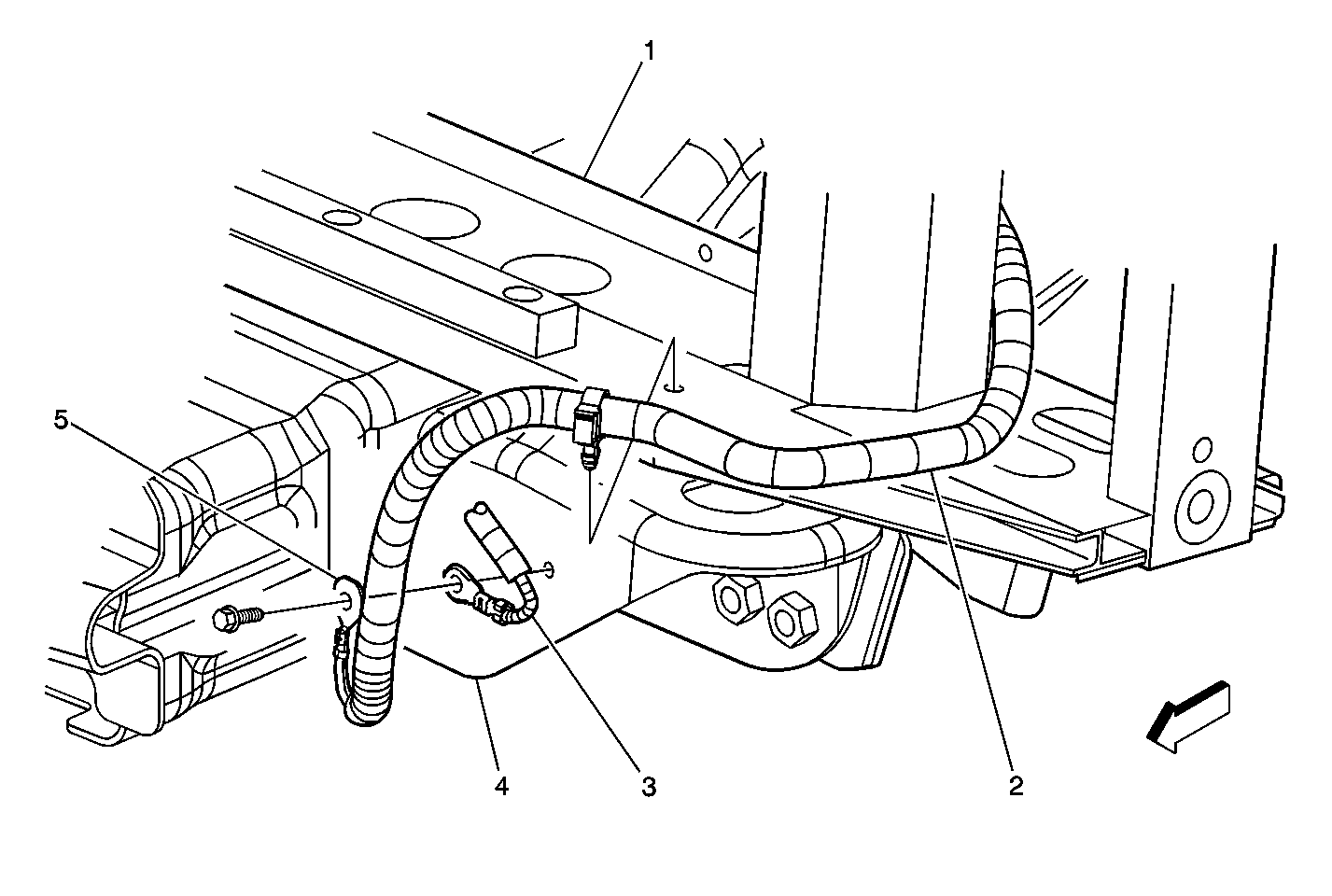
| Figure 1: |
Lower LF of the Radiator Support Components
|
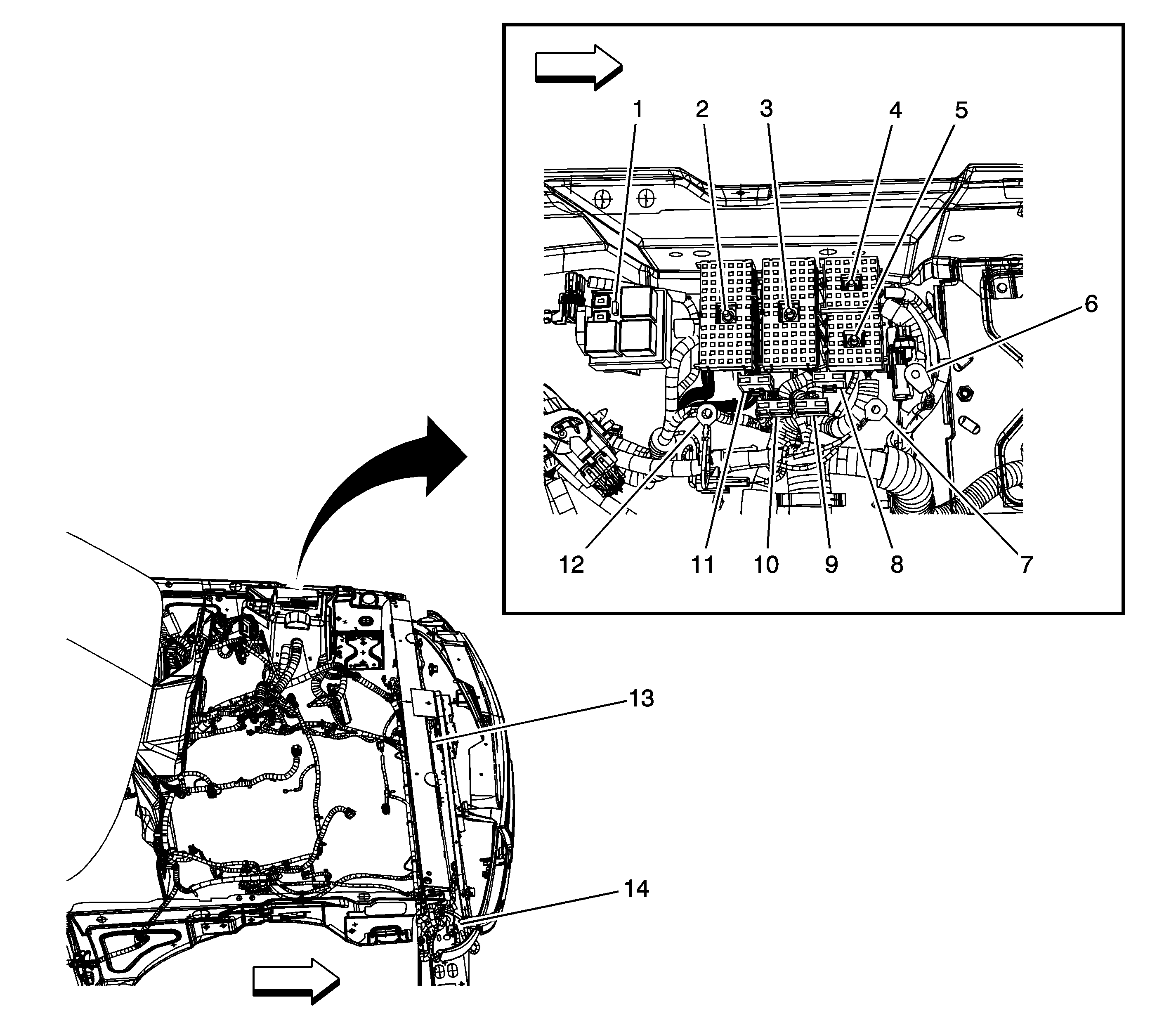
| Figure 2: |
LF of Engine Compartment
|
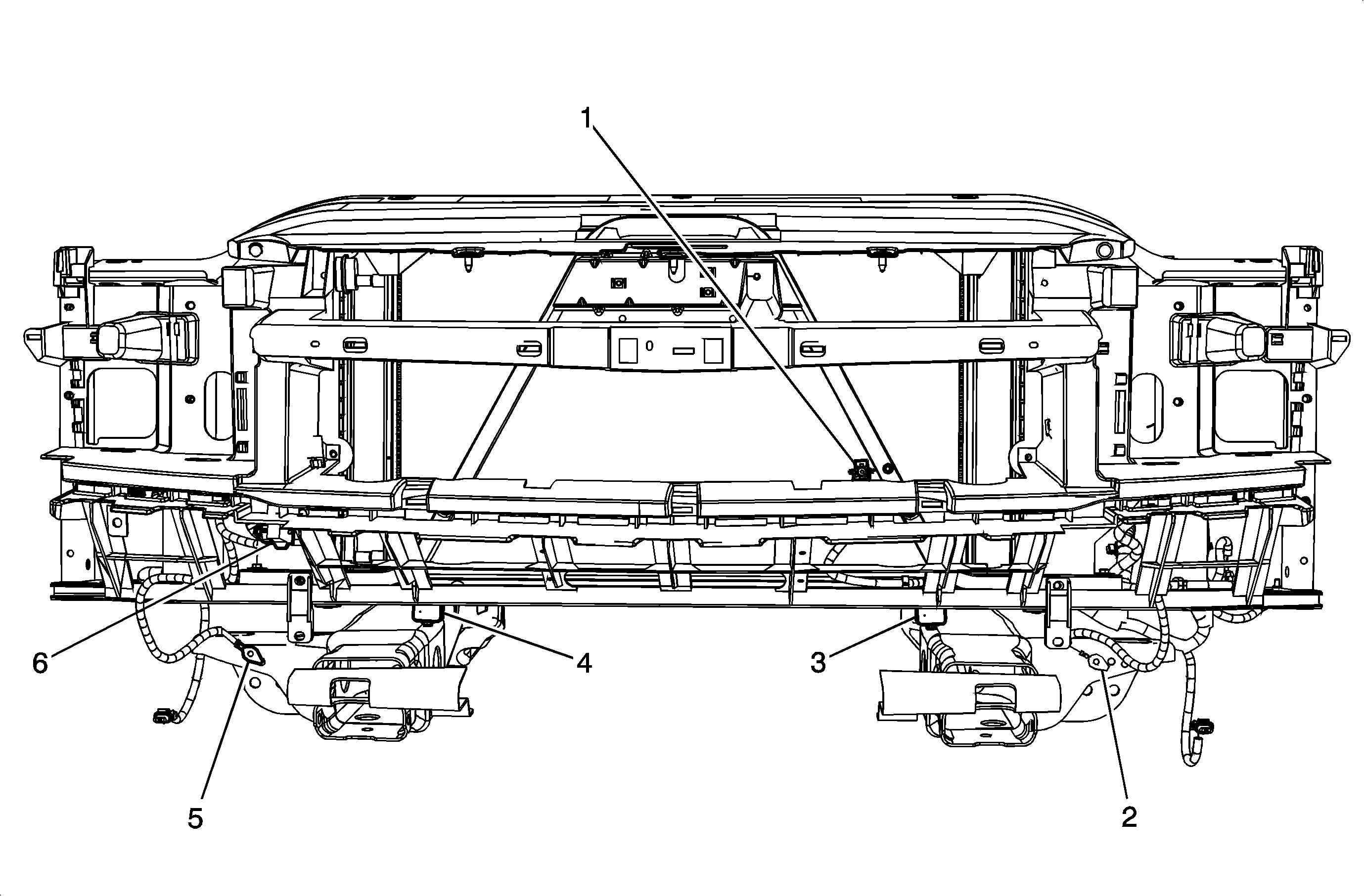
| Figure 3: |
Front of Radiator
|
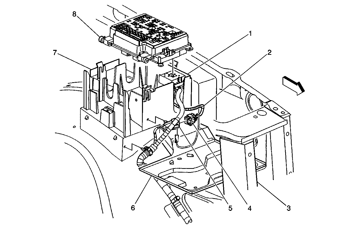
| Figure 4: |
Fuse Block-Underhood
|
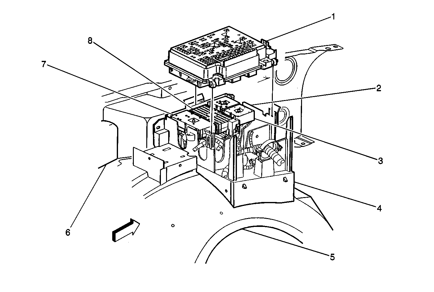
| Figure 5: |
Fuse Block-Underhood Connectors
|
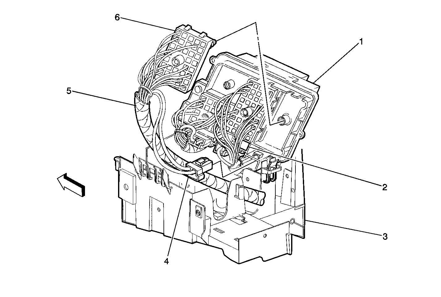
| Figure 6: |
Fuse Block-Underhood-C1 (LT GRY) and C6 (BRN)
|
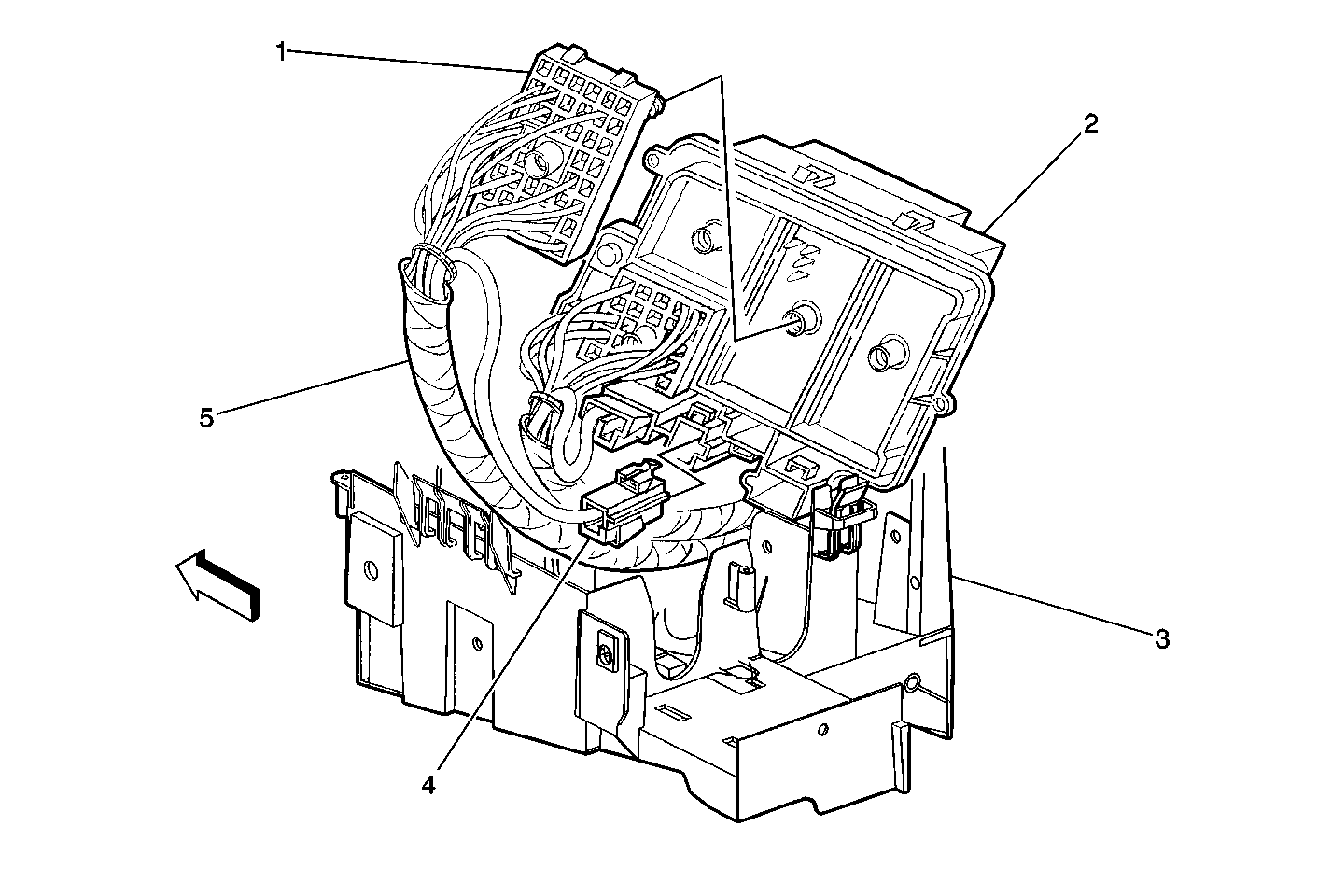
| Figure 7: |
Fuse Block-Underhood-C2 (BLK) and C5 (BLK)
|
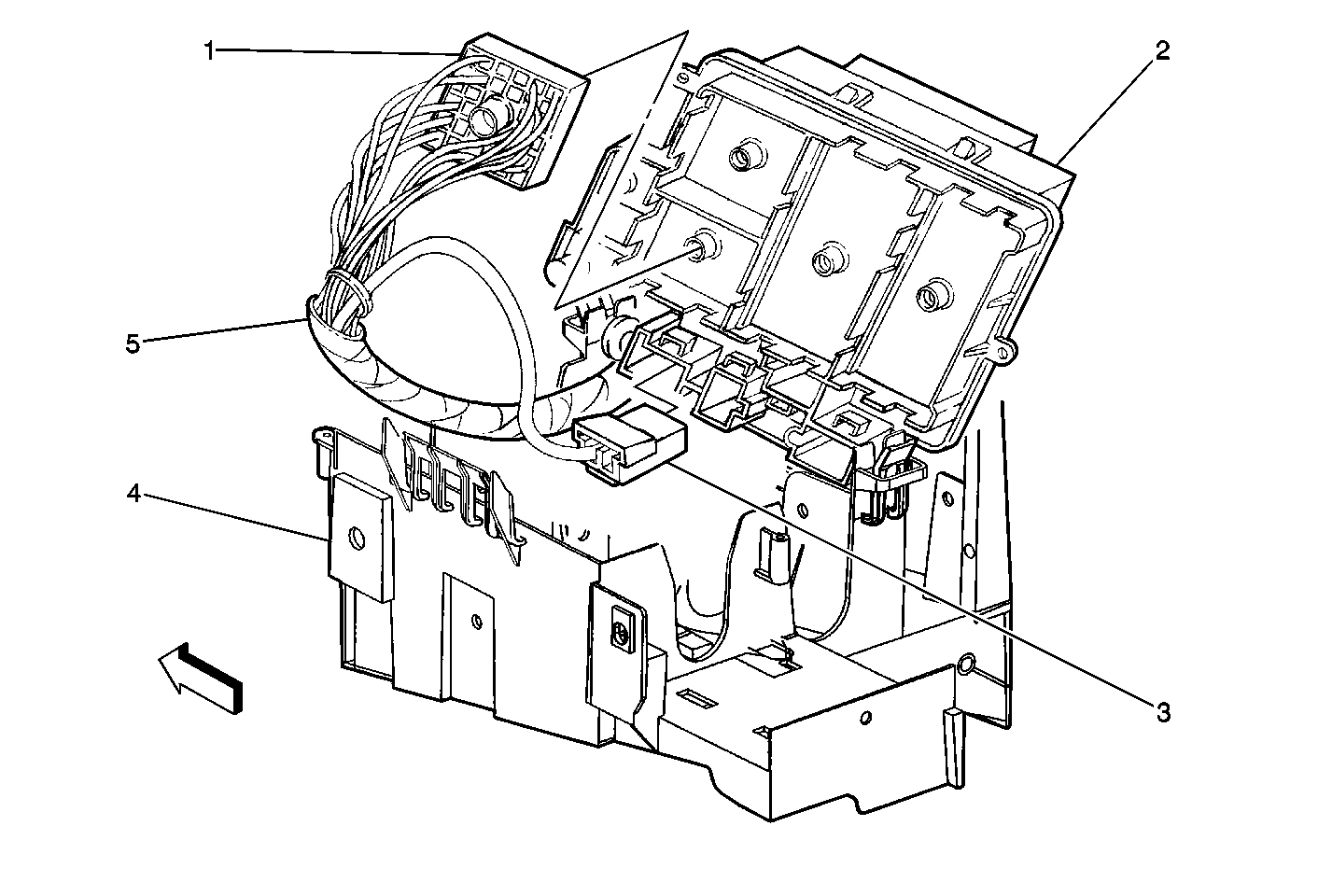
| Figure 8: |
Fuse Block-Underhood-C3 (RED) and C8 (LT GRY)
|
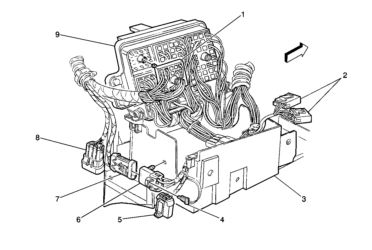
| Figure 9: |
Fuse Block-Underhood-C4 and Inlines
|
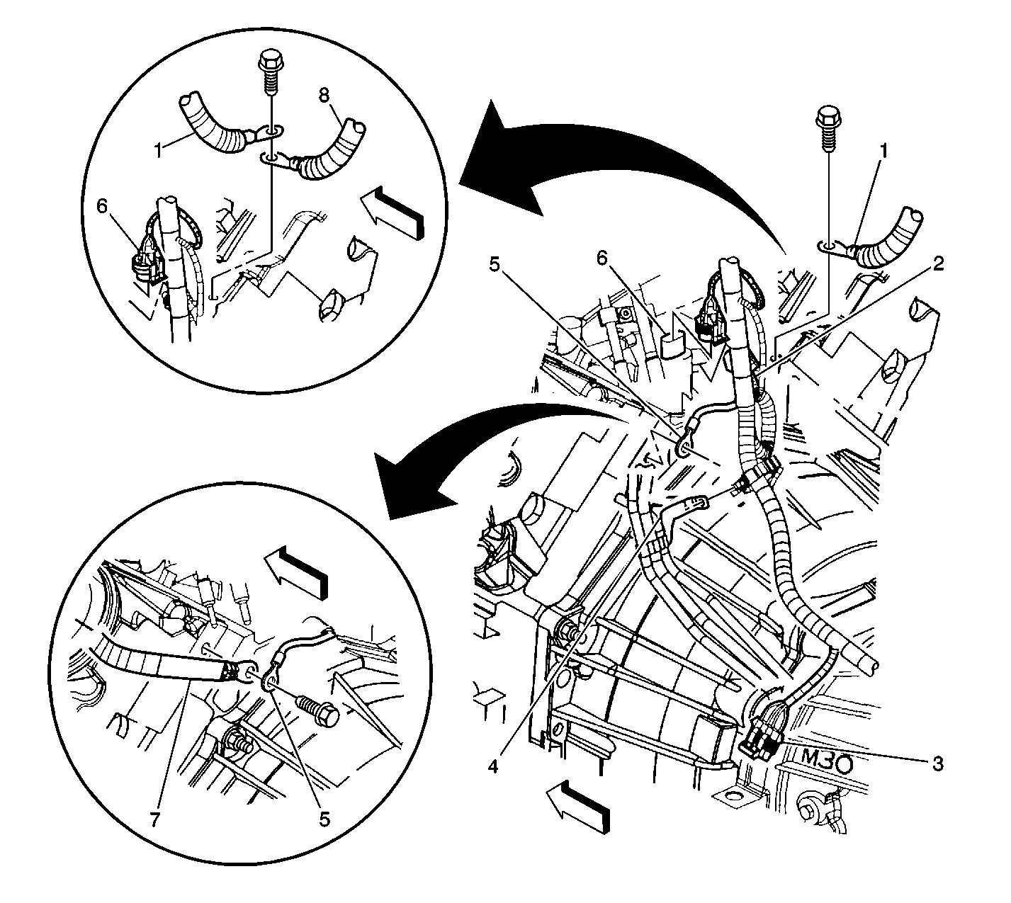
| Figure 10: |
Lower LR of the Engine Components (4.8L/5.3L/6.0L)
|
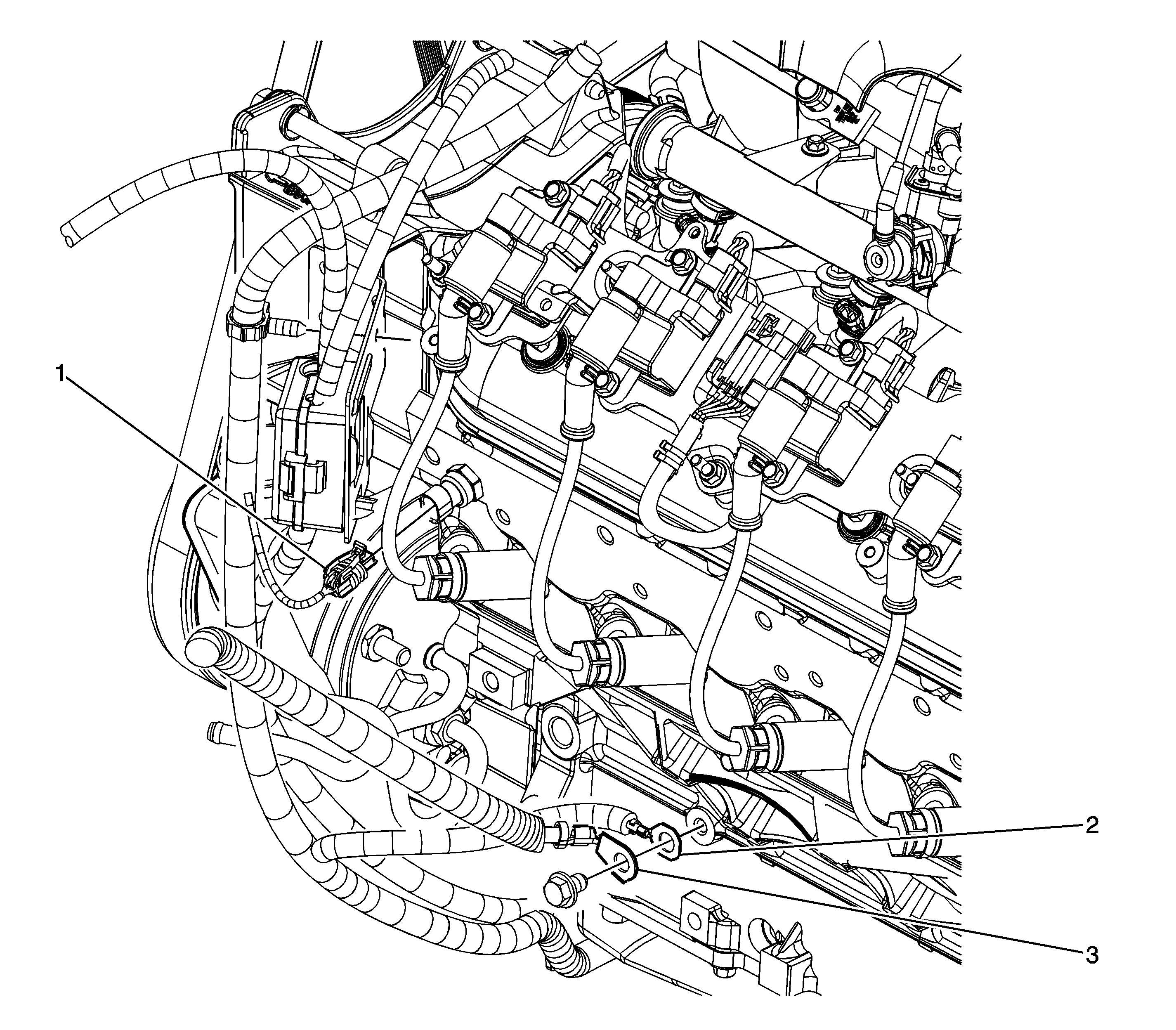
| Figure 11: |
G102 (4.8L, 5.3L, and 6.0L)
|
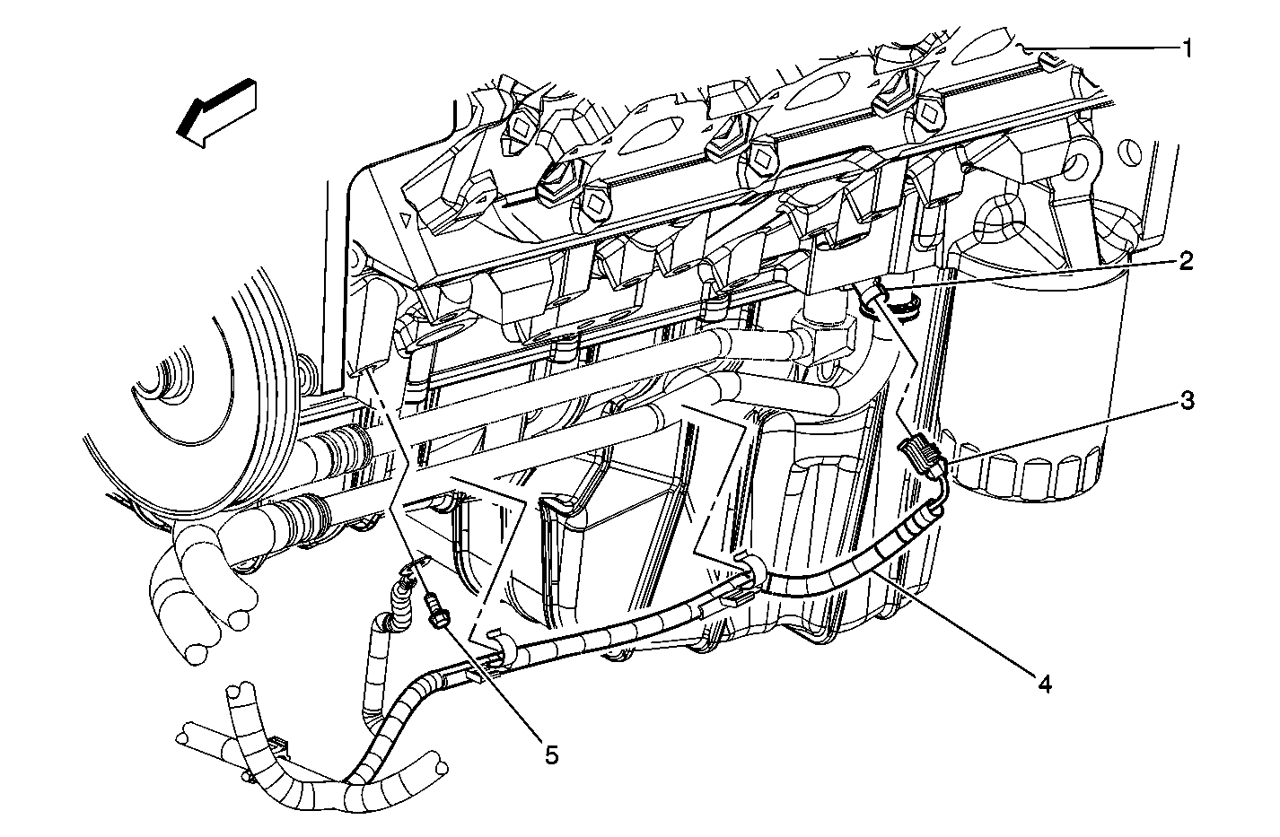
| Figure 12: |
G102 - 8.1L
|
| Figure 13: |
G104-8.1L
|
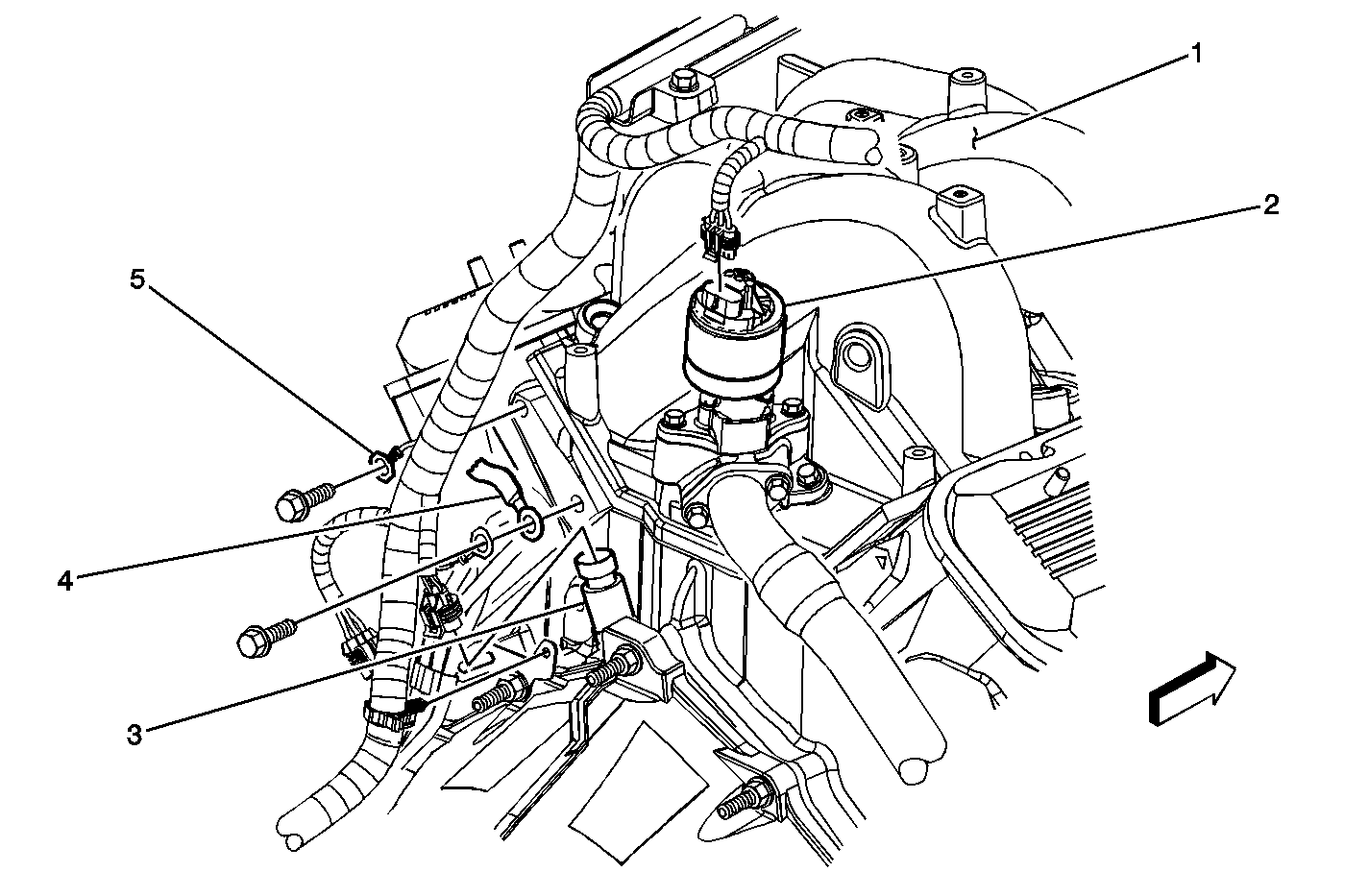
| Figure 14: |
LR of Engine Compartment
|
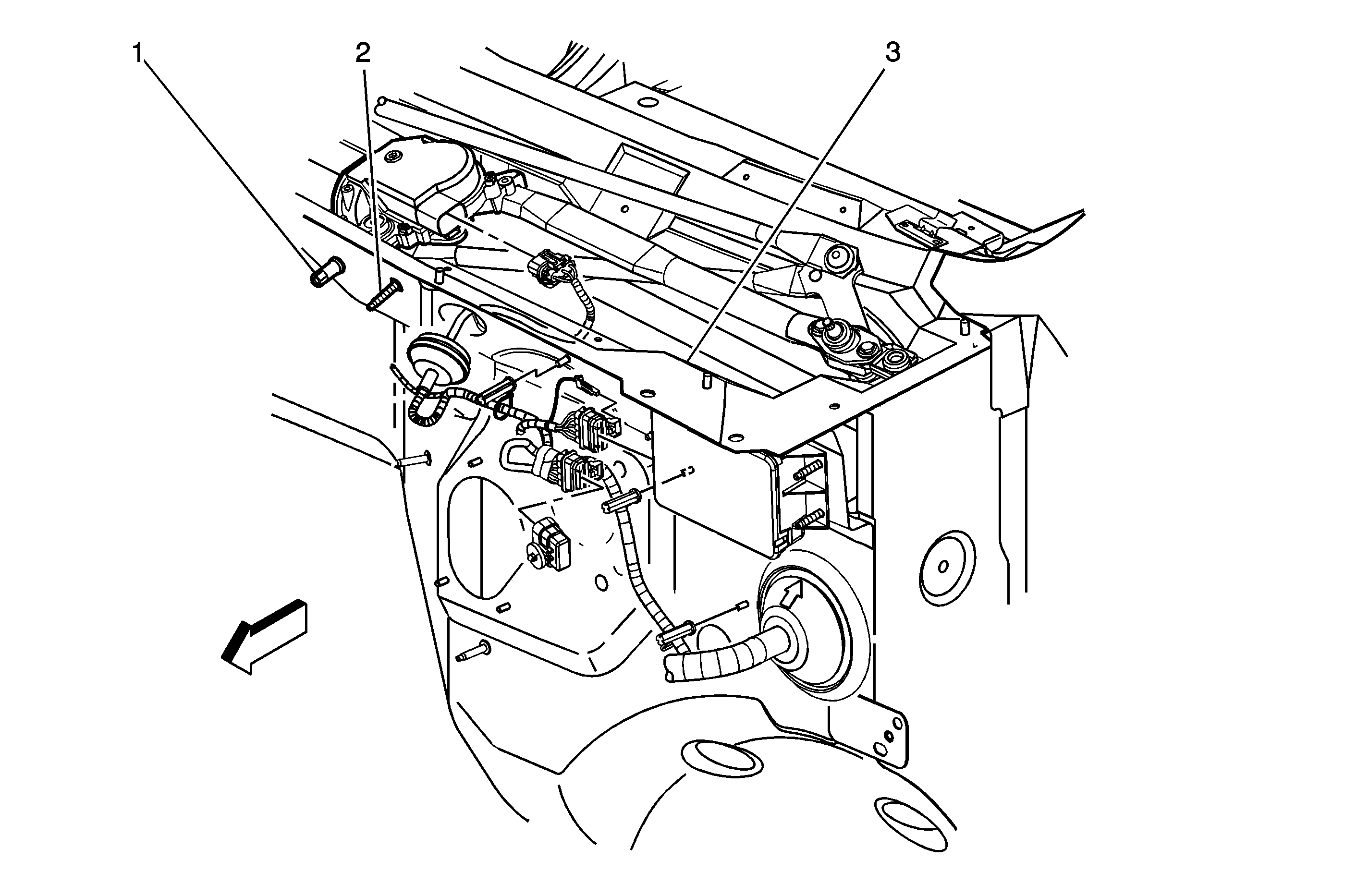
| Figure 15: |
G110 and G302
|
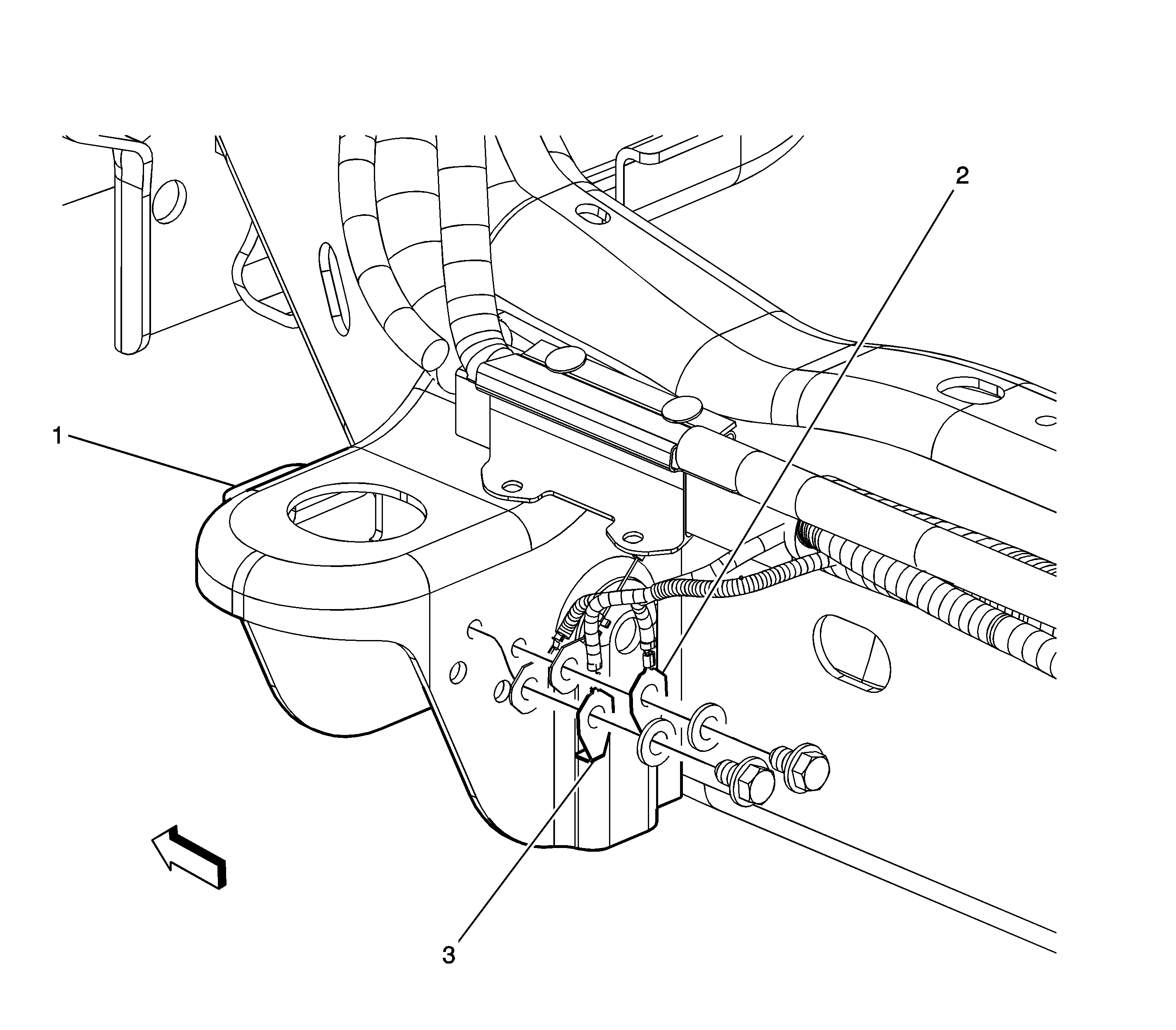
| Figure 16: |
Transfer Case Harness Routing (1500 Series)
|
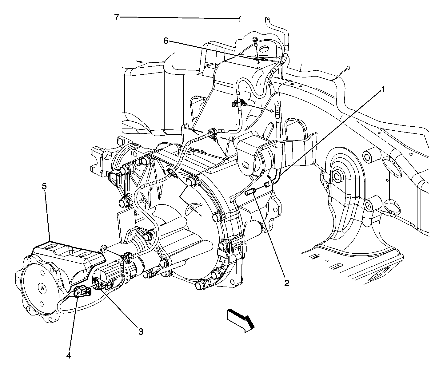
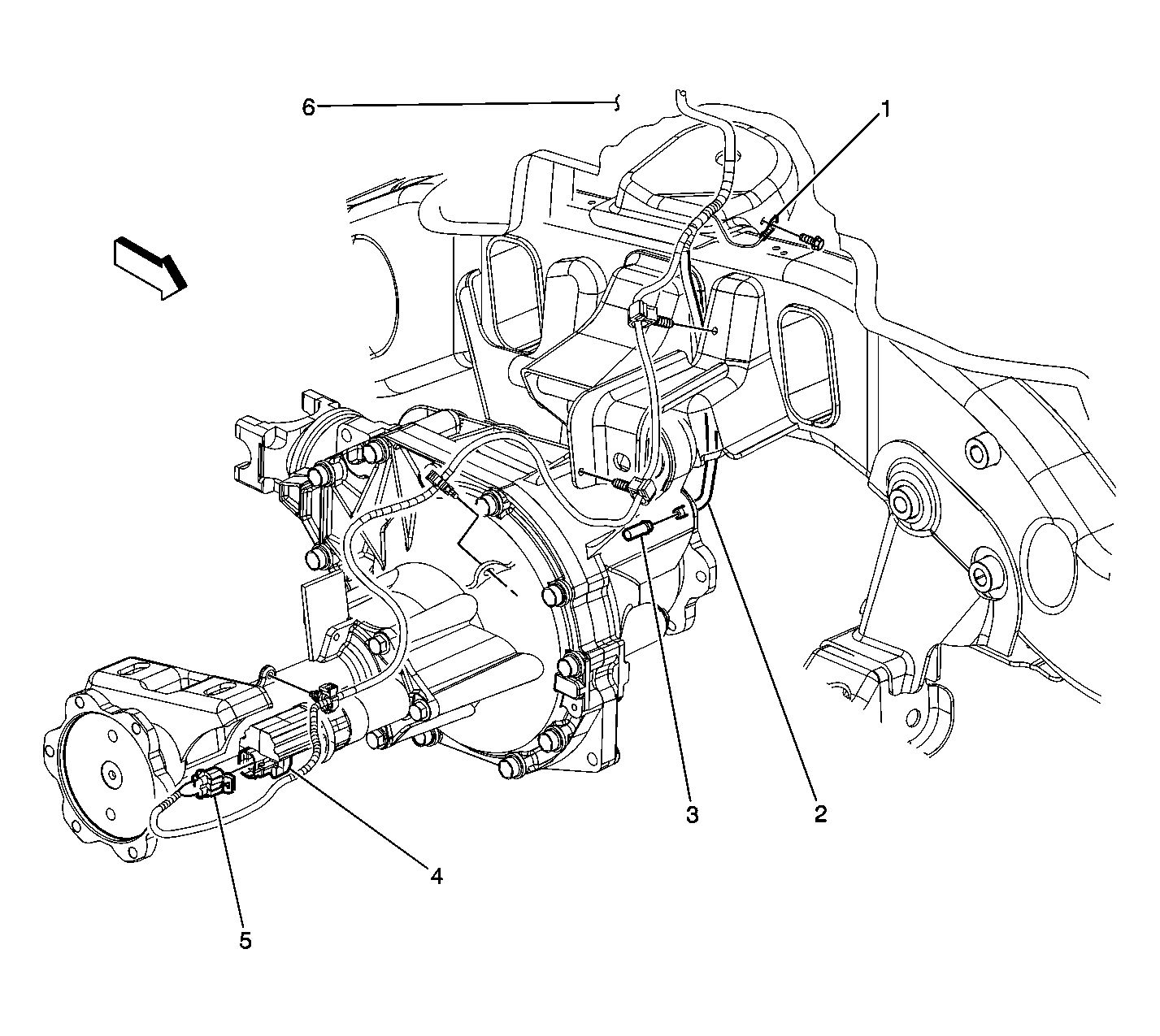
| Figure 17: |
Transfer Case Harness Routing (2500 Series)
|
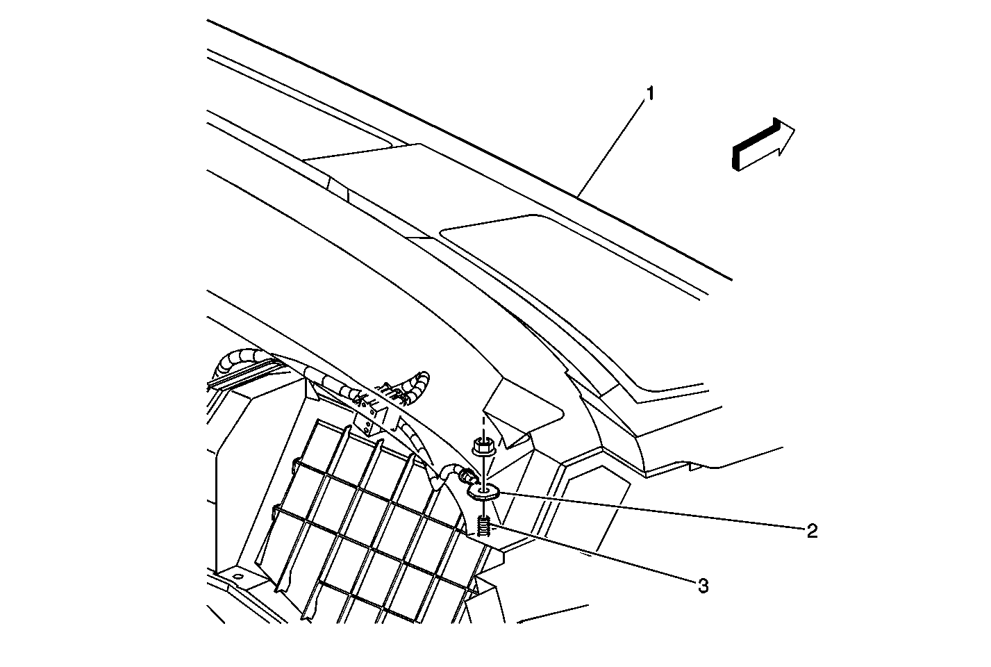
| Figure 18: |
RH Upper Instrument Panel
|
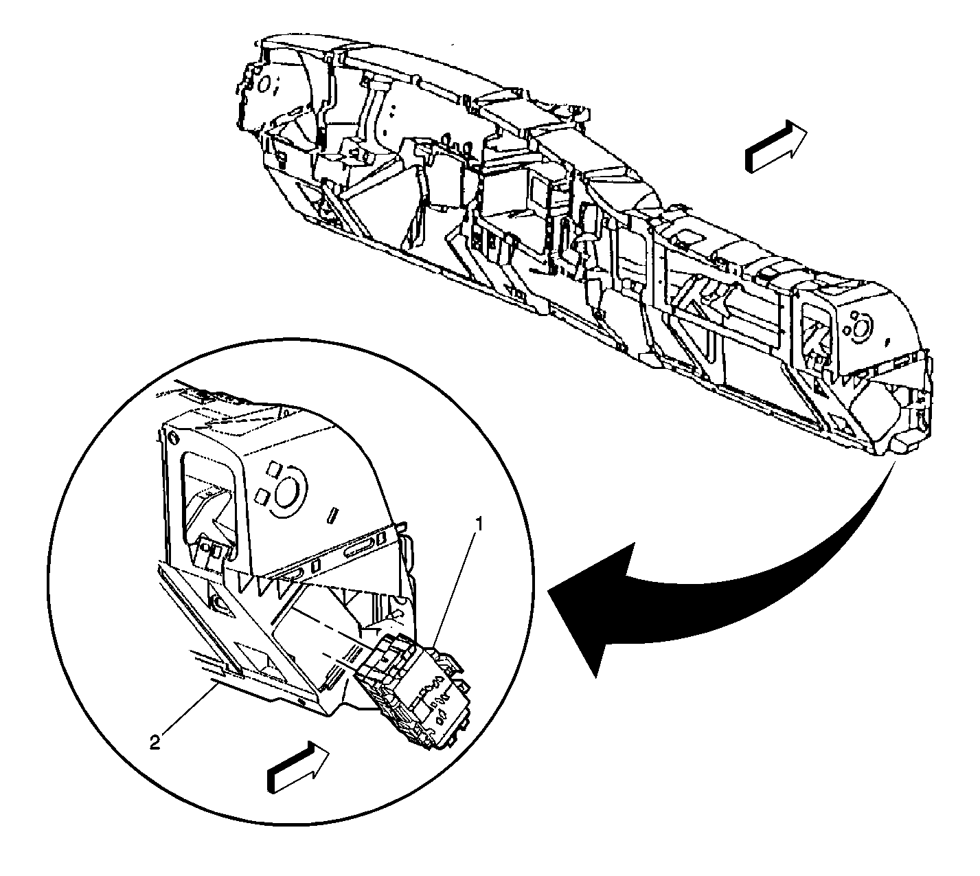
| Figure 19: |
Junction Block- I/P
|
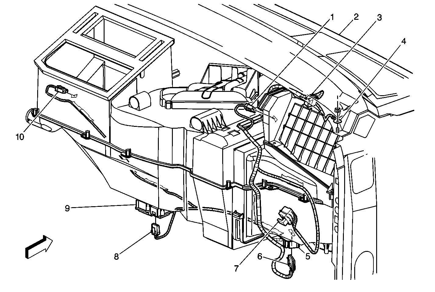
| Figure 20: |
HVAC Module Assembly (Connections)
|
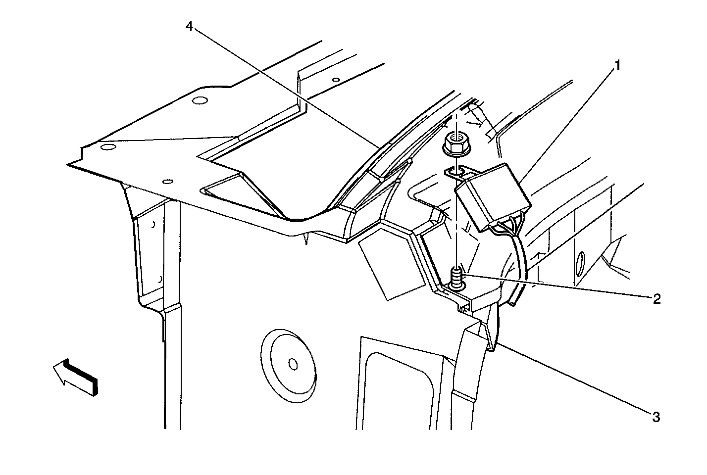
| Figure 21: |
Upper Left of the I/P Components
|
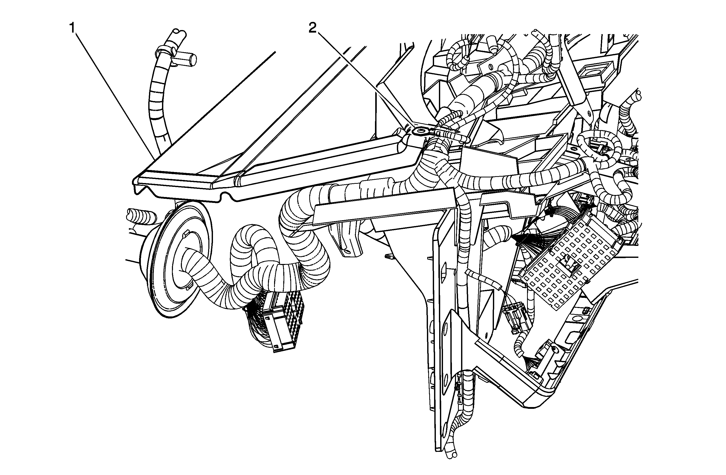
| Figure 22: |
Upper Left of I/P - G203
(w/ULT)
|
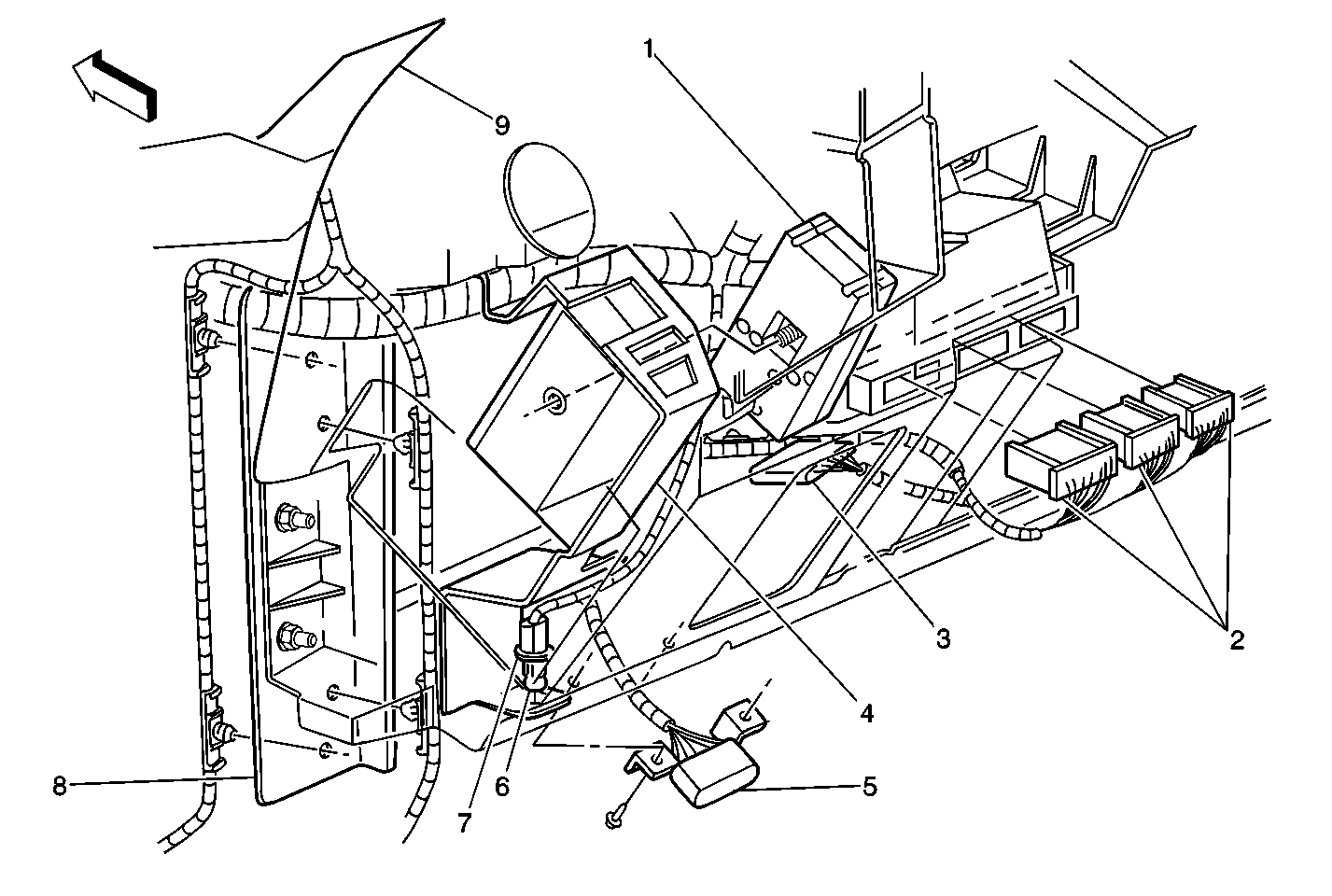
| Figure 23: |
Left Hand Lower Dash
|
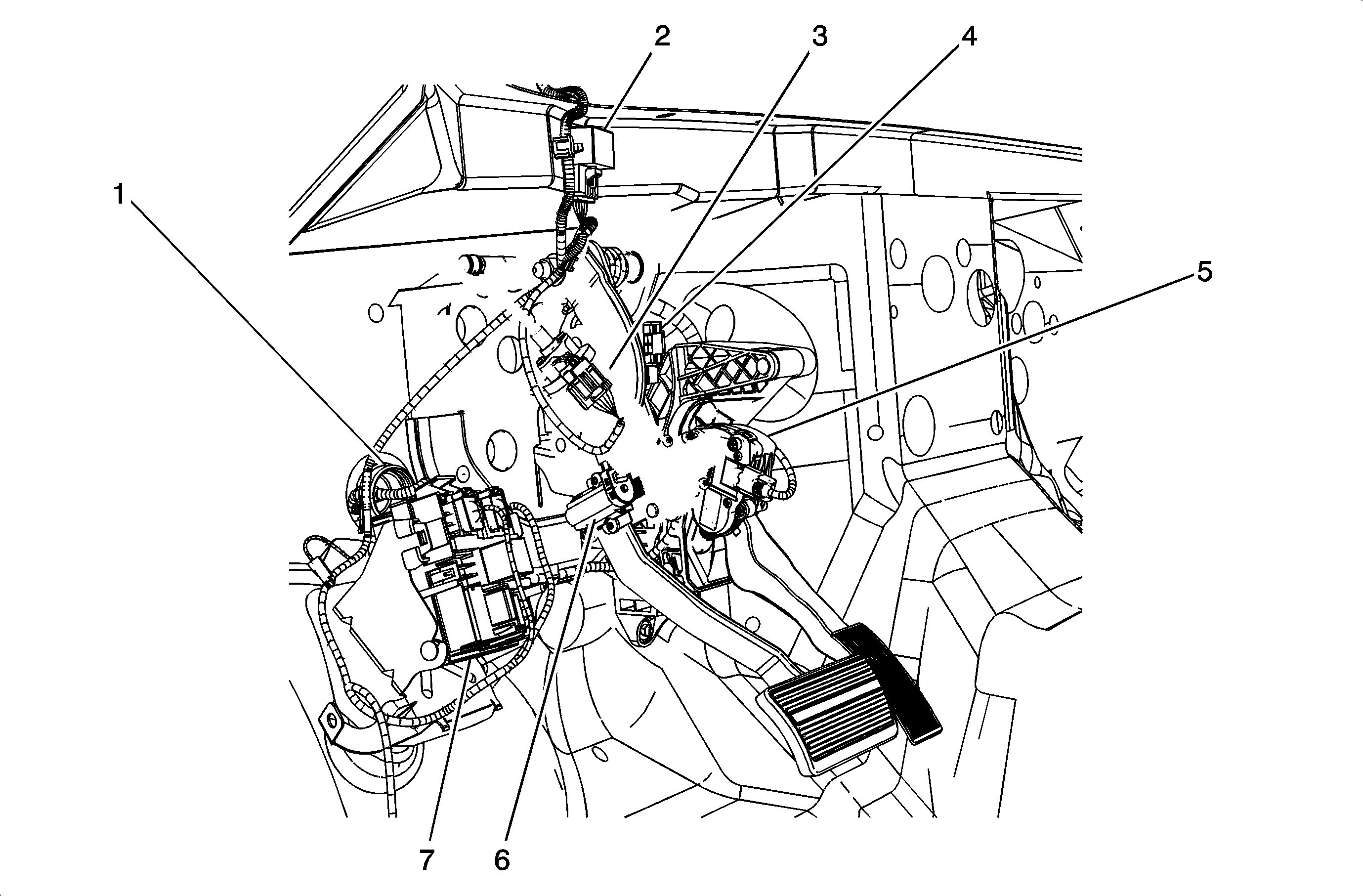
| Figure 24: |
Under I/P - Left Side
|
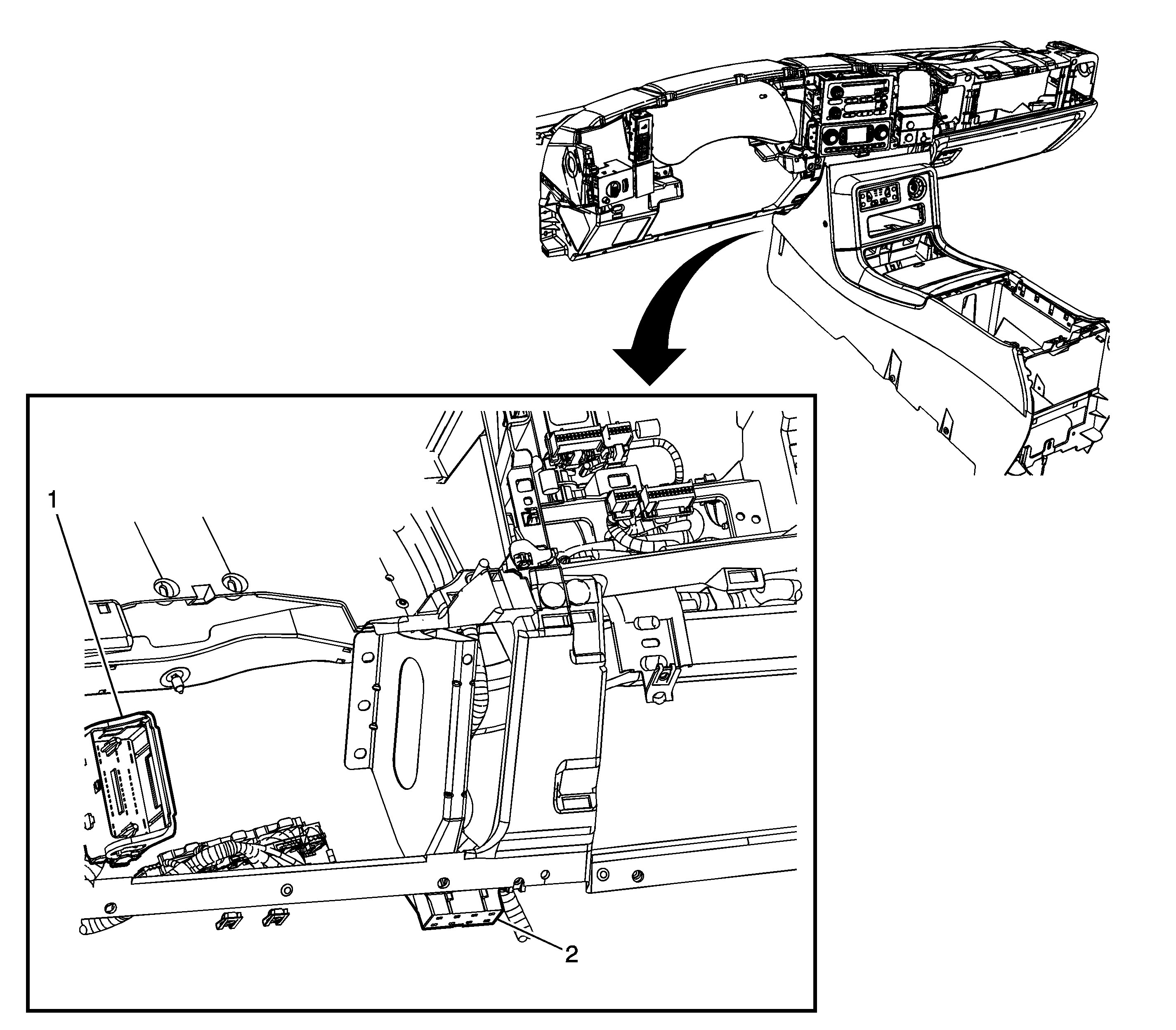
| Figure 25: |
Below the Left Side of the I/P, Near the Base of the Steering Column (Escalade ULT)
|
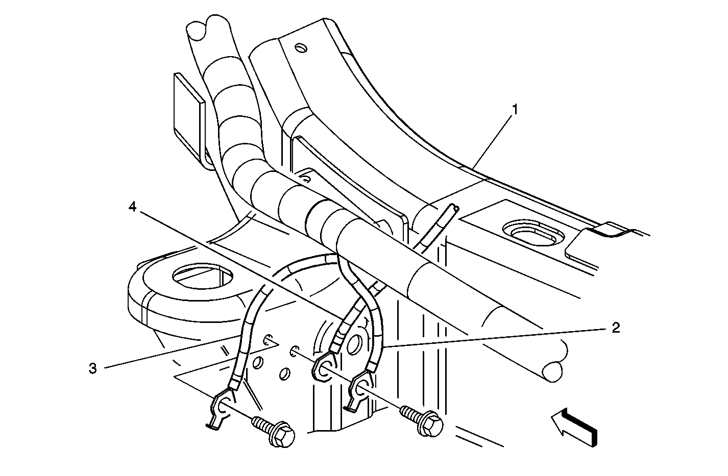
| Figure 26: |
Left Side Frame Rail -- Grounds
|
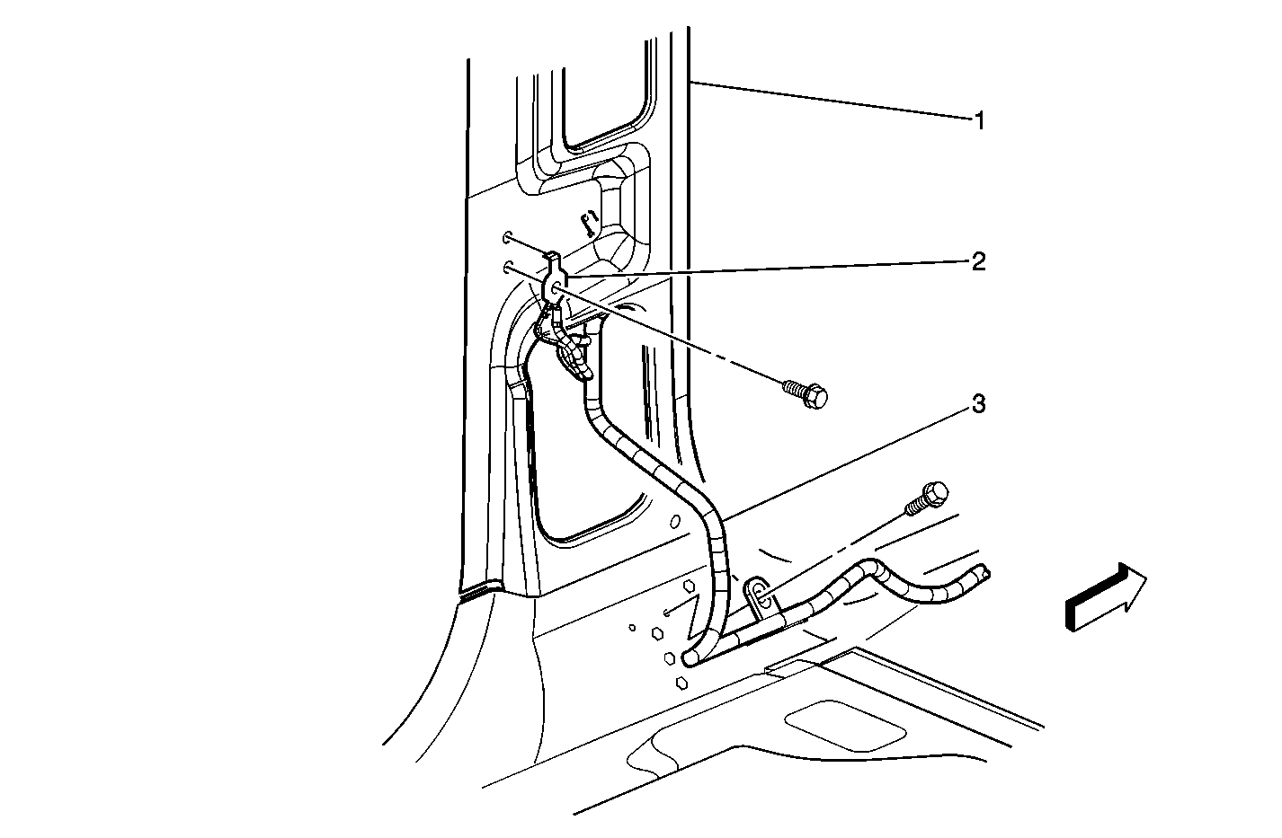
| Figure 27: |
Driver Side B-Pillar Wiring
|
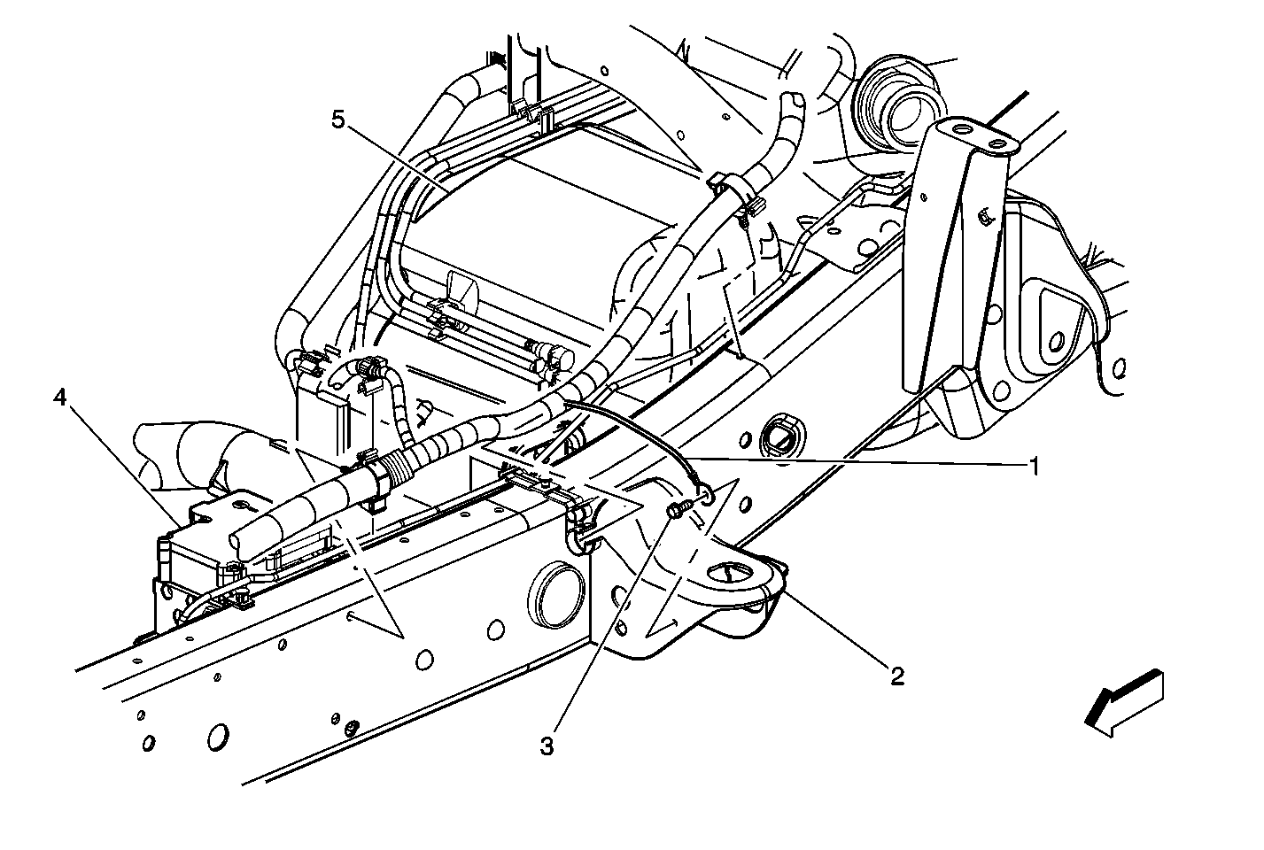
| Figure 28: |
Left Side Frame Rail -- Brake Components
|
| Figure 29: |
RH B-Pillar
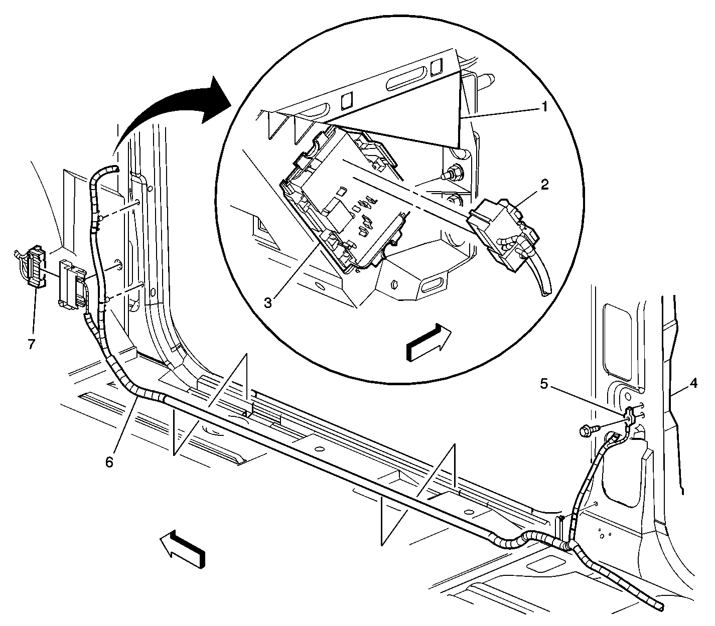
|
| Figure 30: |
G305
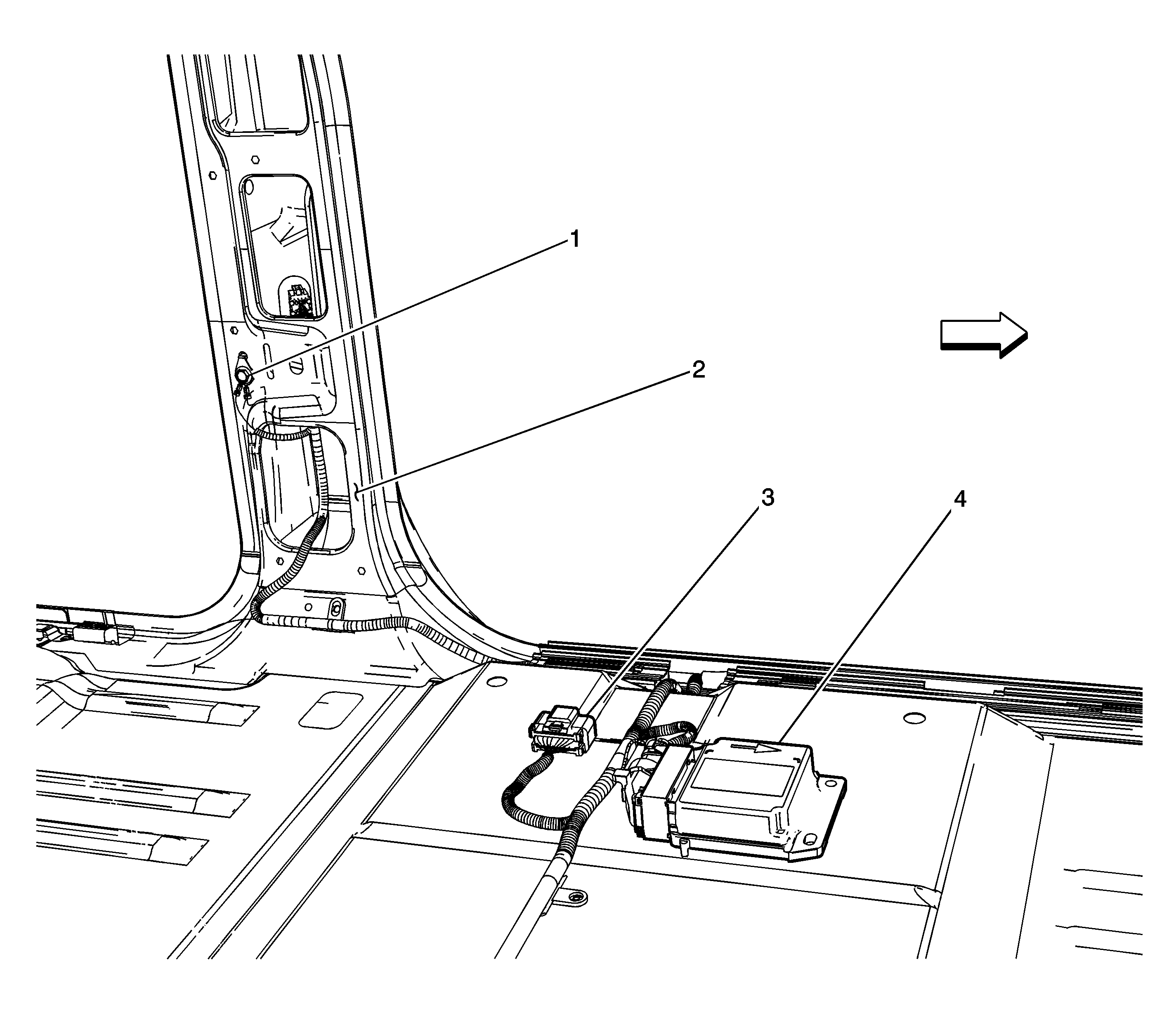
|
| Figure 31: |
G304 and G306
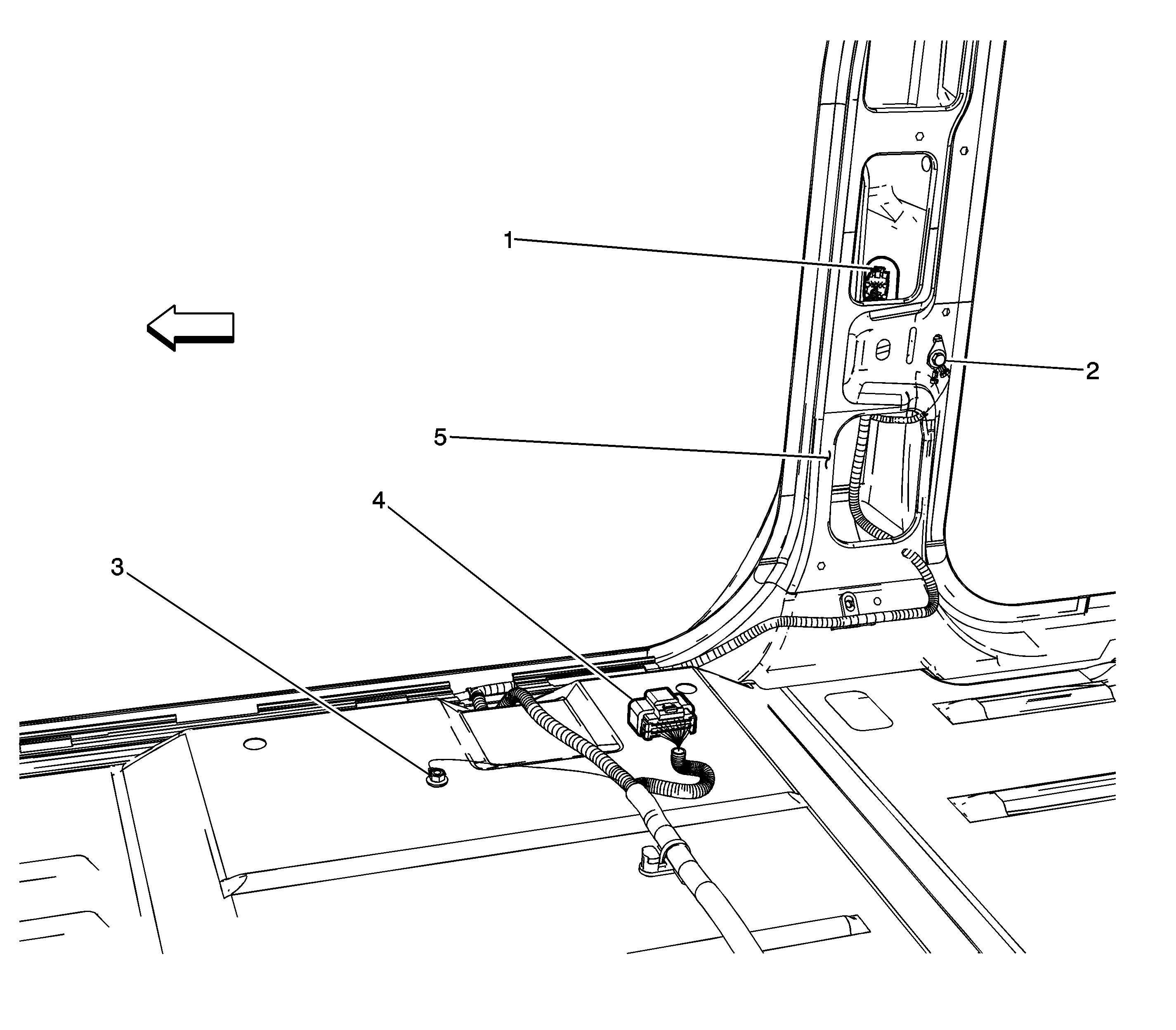
|
| Figure 32: |
Emergency Light Relay and G305-Utility/Crewcab
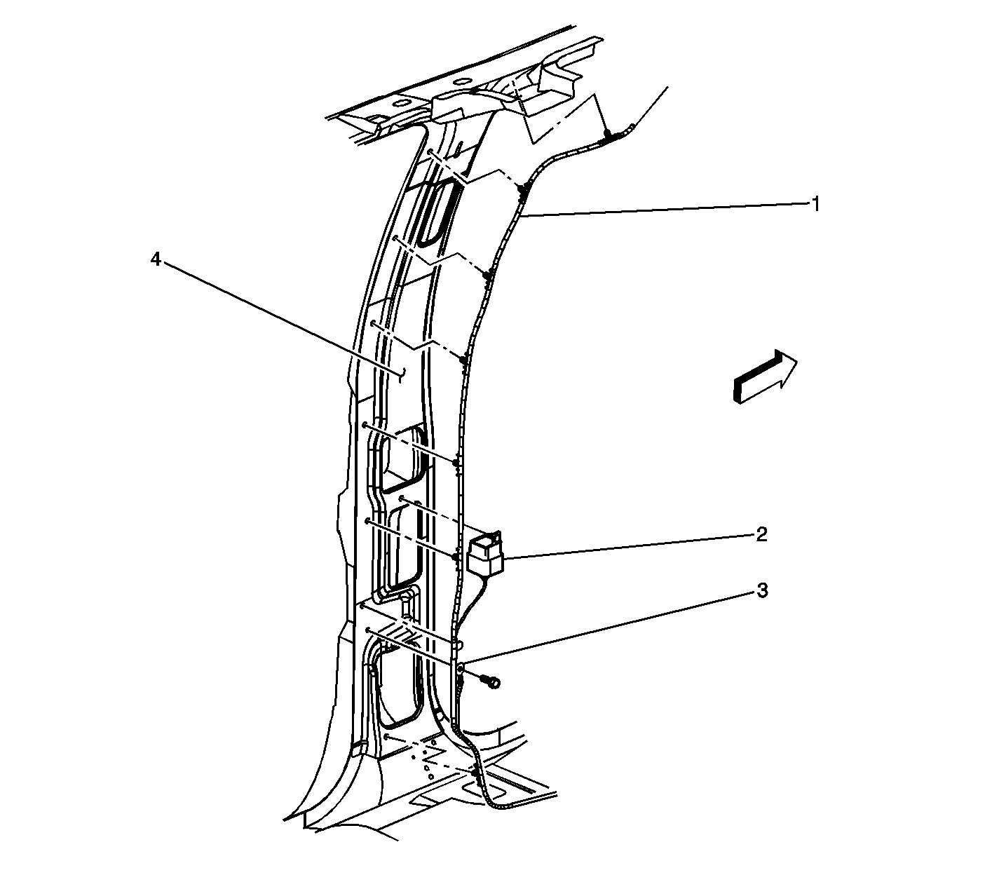
|
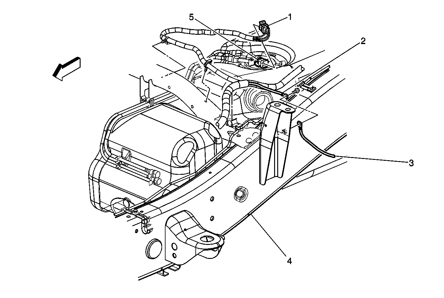
| Figure 33: |
Fuel Tank and Sensor (Typical)
|
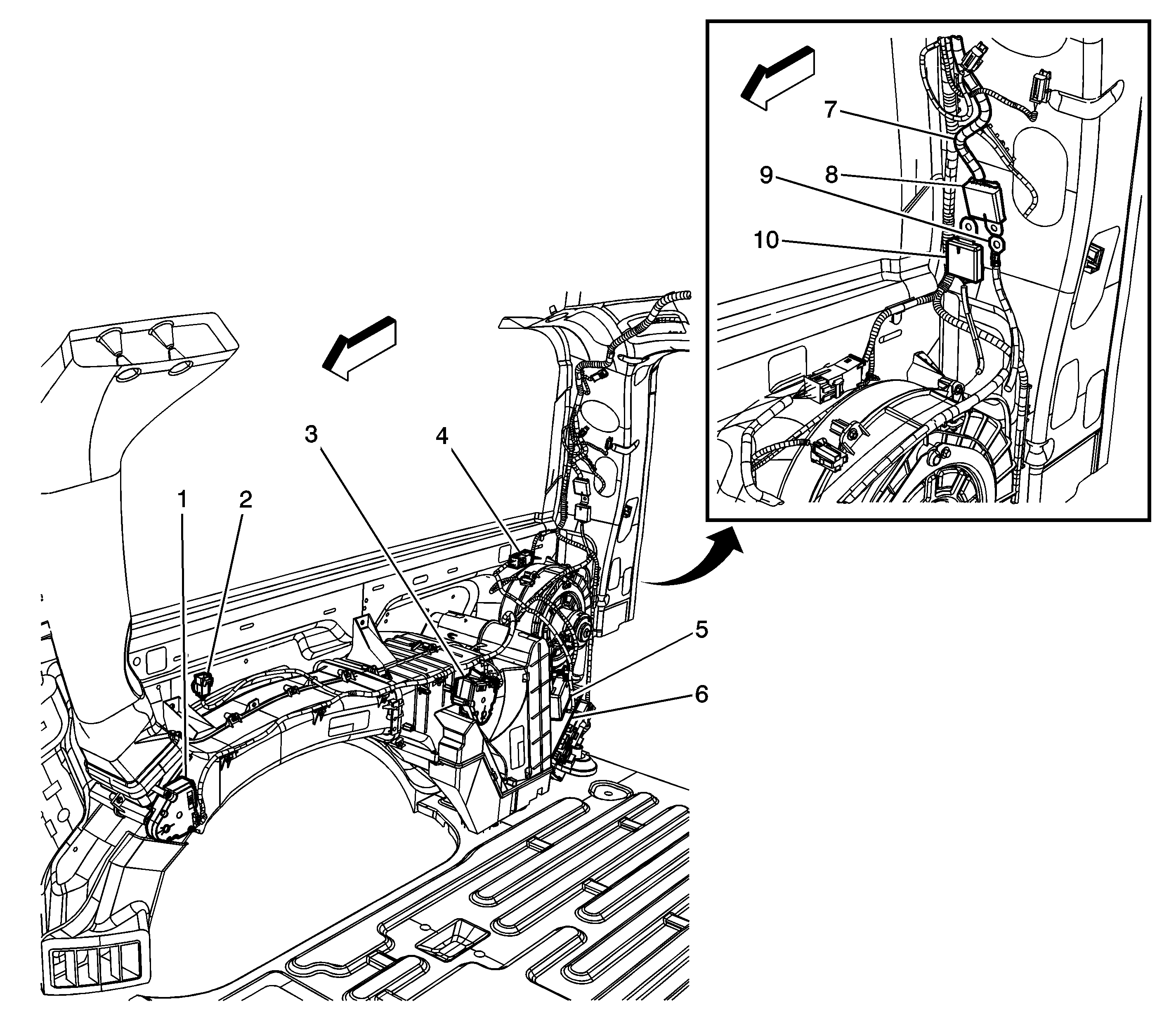
| Figure 34: |
Right Rear of Cargo Area
|