GM Service Manual Online
For 1990-2009 cars only

Schematic Reference: Radio/Audio System Schematics

Diagnostic System Check - Entertainment System

Always perform the Diagnostic System Check before proceeding with these diagnostic procedures. Refer to Diagnostic System Check - Vehicle in Vehicle DTC Information .

Antenna System Test

Important: Always zero out the DMM before taking a resistance measurement in order to ensure an accurate reading.

  1. Disconnect the negative battery cable.
  2. Disconnect the antenna lead-in connector from the radio receiver.
  3. Measure the resistance from the negative battery cable to the coax outer conductor connector.
  4. The resistance measured should be 0.2 ohms or less.
  5. Test the following when the resistance is greater than 0.2 ohms.
  6. • Base of the antenna for a poor connection to body ground
    • The coaxial cable interconnects for a poor connection or corrosion.
    • Test for an open or high resistance from the battery negative cable to the body. Refer to Circuit Testing and Wiring Repairs in Wiring Systems.
  7. After finding and correcting the condition, operate the system in order to verify the repair.

Perform the Antenna Checking Procedures after confirming the integrity of the antenna ground.

Antenna Checking Procedures

Perform the following tests for the type of antenna on the vehicle.

Mast Antennas

Unplug the antenna lead-in connector from the radio receiver and plug a test antenna into the radio. Ensure the antenna base is grounded to the vehicle chassis and keep your hands off the mast.

Important: Always zero out the DMM before taking a resistance measurement in order to ensure an accurate reading.

Check the radio reception in an area away from electrical interferences. Tune to several weak and strong AM and FM stations. If the radio reception improved, the problem exists with the antenna and/or lead-in cable. If the reception is still poor, refer to Audio System Troubleshooting Hints .

Mast Antenna System
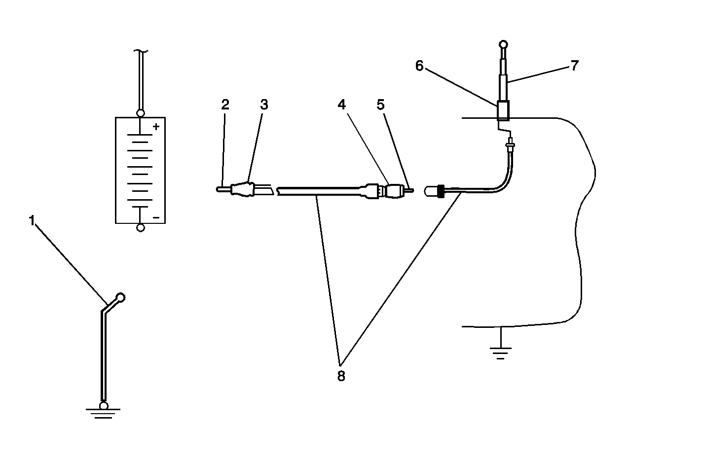

Object Number: 782084  Size: MF
(1)Negative Battery Cable
(2)Coaxial Cable Conductor - Radio End
(3)Coaxial Cable Metal Outer Shield - Radio End
(4)Coaxial Cable Metal Outer Shield - Antenna End
(5)Coaxial Cable Conductor - Antenna End
(6)Antenna Base
(7)Antenna Mast
(8)Antenna Coaxial Cable

Ohmmeter Probes At Points

Resistance Measured In Ohms

1 and 3

Less than 0.2

1 and 4

Less than 0.2

1 and 6

Less than 0.2

1 and 2

Infinite

1 and 5

Infinite

1 and 7

Infinite

2 and 3

Infinite

2 and 4

Infinite

2 and 6

Infinite

3 and 4

Less than 0.2

3 and 6

Less than 0.2

3 and 5

Infinite

3 and 7

Infinite

Refer to the table when testing the antenna and/or lead-in cable.

  1. Measure the resistance from the coax center conductor to antenna mast.
  2. Total resistance from end to end of center conductor:
  3. • RG-58/RG-59 type cable--Less than 0.2 ohms
    • RG-62/RG-62M type cable--Less than 3.5 ohms
  4. When checking the resistance, cautiously wiggle the lead-in tip and cable. Refer to Testing for Intermittent Conditions and Poor Connections in Wiring Systems.
  5. Measure the resistance from the cable center conductor to metal case.
  6. Replace the antenna and/or lead-in cable when the above readings are not obtained.

Diversity Antenna System

Important: This diversity antenna system is comprised of 3 glass mounted antennas, a radio antenna module, and an FM impedance matching module. The primary AM and FM antennas are an integral part of the left rear quarter glass and are connected to the radio antenna module. The secondary FM antenna is an integral part of the right rear quarter glass and is connected to the FM impedance matching module. The radio antenna module processes the antenna reception signals and phase aligns them to create one strong signal. The FM impedance matching module boosts the secondary antenna signal and transmits it to the radio antenna module.

The following information lists the most probable cause of the concern to the least probable cause followed by the appropriate test for that condition. If the test leads to the replacement of a component, always inspect for a poor connection before proceeding with the replacement. If the test leads to the replacement of a component, always inspect for a poor connection before proceeding with the replacement. Refer to Testing for Intermittent Conditions and Poor Connections and Connector Repairs in Wiring Systems.

Perform the Antenna System Test and test the antenna coax cable prior to performing any of the following tests.

Poor Reception on Both AM and FM Bands

    • The radio antenna module is not grounded properly. The module grounding screws should be clean and tight. The antenna module ground is either a chassis ground or a ground strap. Measure the resistance from the antenna module base plate to a good ground. Resistance should be 0.2 ohms or less. Find and correct the condition if the resistance is out of specification.
    • The antenna enable signal is not present at the radio antenna module. This could be caused by an output failure of the radio or an open/shorted antenna enable signal circuit. In order to test the antenna enable signal circuit, the radio must be ON and tuned to the FM band. Disconnect the radio antenna module. Measure the voltage from the antenna enable signal circuit of the radio antenna module to a good ground. Voltage measured should be near 12 volts. If the specified voltage is measured, test the antenna enable signal circuit for an open or short to ground. Refer to Circuit Testing and Wiring Repairs in Wiring Systems. If no failures were found, replace the radio. Refer to Control Module References in Computer/Integrating Systems for replacement, setup, and programming.
    • The FM composite signal circuit to the radio antenna module is open or shorted to ground. Test the FM composite signal circuit for an open or short to ground. Refer to Circuit Testing and Wiring Repairs in Wiring Systems.
    • The feed coax at the radio antenna module has been inadvertently swapped with the FM impedance matching module crossover coax. Ensure that the feed coax, marked with a yellow band, is in the correct socket on the radio antenna.
    • Improper retention of the antenna cable in the floating retainer--Poor or no connection with the radio will result when the radio is installed if the antenna cable is not properly attached in the floating retainer. Inspect the antenna cable for movement in the floating retainer. Replace the antenna cable if movement is found.
    • Defective radio control module--Replace the radio control module. Refer to Control Module References in Computer/Integrating Systems for replacement, setup, and programming.

Poor Reception on AM Band Only

    • Defective AM antenna
    • Defective radio control module--Replace the radio control module. Refer to Control Module References in Computer/Integrating Systems for replacement, setup, and programming.

Poor Reception on FM Band Only

    • Defective primary or secondary FM antenna
    • Defective radio control module--Replace the radio control module. Refer to Control Module References in Computer/Integrating Systems for replacement, setup, and programming.
    • Defective radio antenna module--Replace the radio antenna module. Refer to Control Module References in Computer/Integrating Systems for replacement, setup, and programming.