Exhaust Muffler Replacement 4.8L,5.3L
Tools Required
J 38185
Hose Clamp Pliers
Removal Procedure
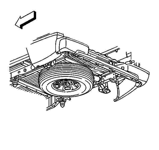
- Remove the spare tire wheel stowage lock cylinder.
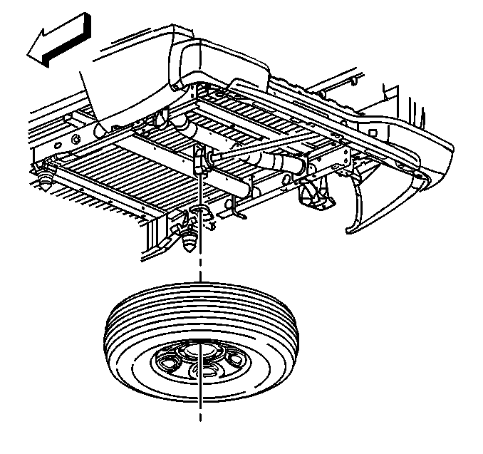
- Remove the spare tire from the hoist.
- Remove the rear tires and wheels. Refer to
Tire and Wheel Removal and Installation
.
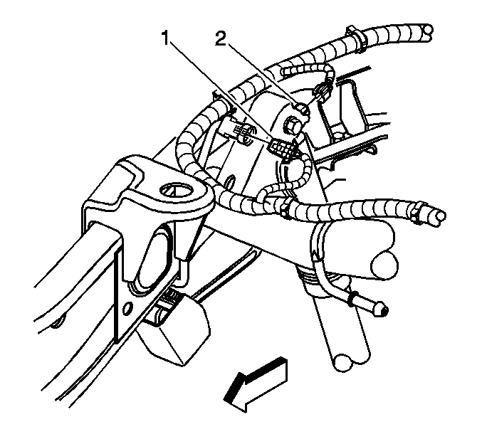
- If vehicle is equipped with regular production option (RPO) Z55, disconnect
the following right side chassis harness electrical connectors:
| • | Electronic suspension rear position sensor (1) |
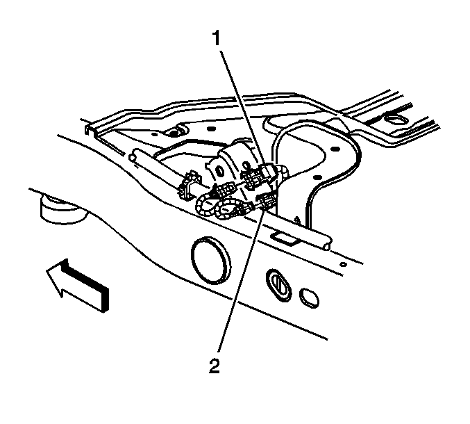
- If vehicle is equipped with RPO Z55, disconnect the following left side chassis
harness electrical connectors:
| • | Electronic suspension rear position sensor (1) |
Important: Do not attempt to pry the rear suspension sensor link rod from the rear position sensor ball stud.
- Remove the left and right sensor link rods from the sensors, perform the following:
| 6.1. | Support the sensor lever with your hand |
| 6.2. | Twist the link rod in order to remove it from the ball stud |
- Install adjustable jack stands under the rear axle.
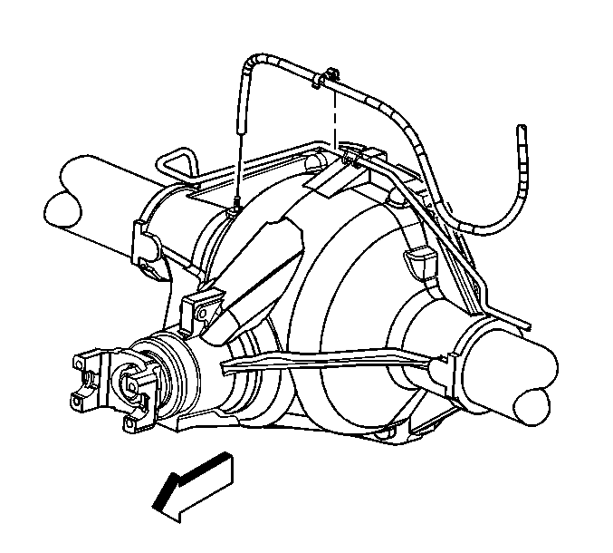
- Remove the rear axle vent hose from the rear axle, if necessary.
- Remove the vent hose swivel clip from the rear brake crossover pipe.
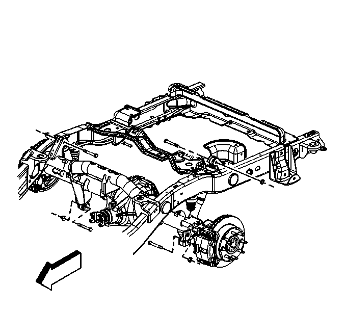
- Remove the rear shock absorbers lower bolts and nuts.
- Lower the rear axle slightly, using the adjustable jack stands, in order to remove the muffler.
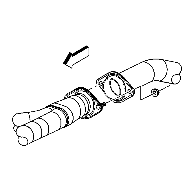
- Remove the exhaust muffler nuts.
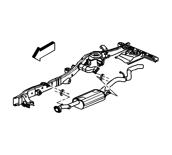
- Remove the muffler from the insulators.
Installation Procedure

- Apply lubricant to the exhaust insulators in order to aid in installation.
- Install the muffler to the insulators.

Notice: Use the correct fastener in the correct location. Replacement fasteners
must be the correct part number for that application. Fasteners requiring
replacement or fasteners requiring the use of thread locking compound or sealant
are identified in the service procedure. Do not use paints, lubricants, or
corrosion inhibitors on fasteners or fastener joint surfaces unless specified.
These coatings affect fastener torque and joint clamping force and may damage
the fastener. Use the correct tightening sequence and specifications when
installing fasteners in order to avoid damage to parts and systems.
- Install the exhaust muffler nuts.
Tighten
Tighten the nuts to 40 N·m (30 lb ft).

- Raise the rear axle, using the adjustable jackstands.
- Install the lower bolts and nuts to the rear shock absorbers.
Tighten
Tighten the bolts to 95 N·m (70 lb ft).
- Remove the adjustable jack stands from under the rear axle.

- Install the vent hose swivel clip to the rear brake crossover pipe.
- Install the rear axle vent hose to the rear axle, if necessary.
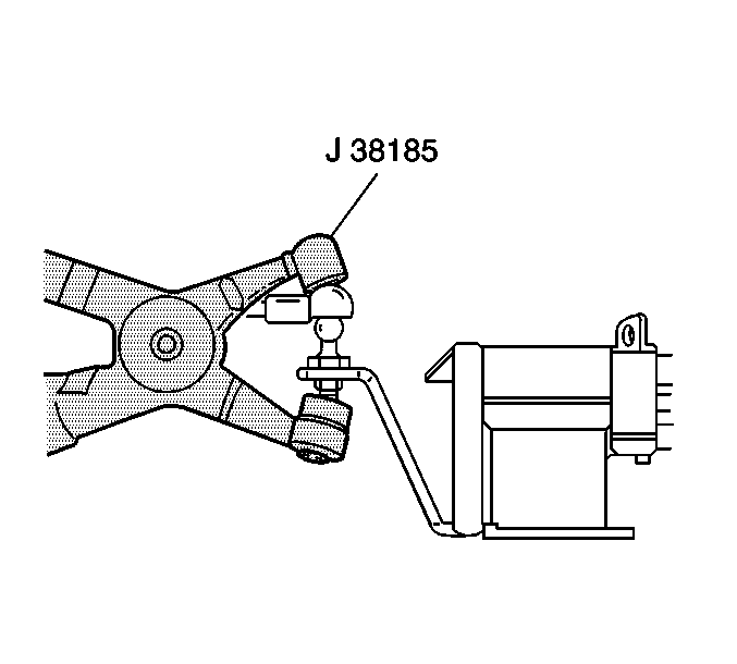
- If vehicle is equipped with RPO Z55, install the left and right sensor link rods to the sensors.
- Using
J 38185
install the link rods to the ball studs on the sensor levers.

- If vehicle is equipped with RPO Z55, connect the following left side chassis
harness electrical connectors:
| • | Electronic suspension rear position sensor (1) |

- If vehicle is equipped with RPO Z55, connect the following right side chassis
harness electrical connectors:
| • | Electronic suspension rear position sensor (1) |
- Install the rear tires and wheels. Refer to
Tire and Wheel Removal and Installation
.

- Install the spare tire to the hoist.

- Install the spare tire wheel stowage lock cylinder.
Exhaust Muffler Replacement 6.0L and 8.1L Engines
Removal Procedure
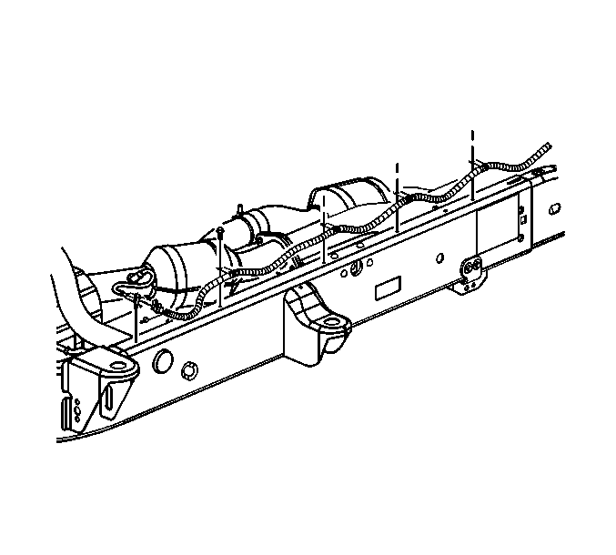
- Raise and suitably support the vehicle.
Refer to
Lifting and Jacking the Vehicle
in General Information.
- Unclip the oxygen sensor connector from the frame.
- Disconnect the connector position assurance (CPA) retainer.
- Disconnect the oxygen sensor electrical connector.
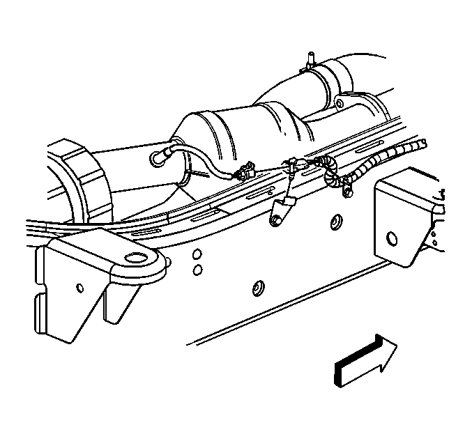
- Unclip the oxygen sensor connector from
the support.
- Disconnect the CPA retainer.
- Disconnect the oxygen sensor electrical connector.
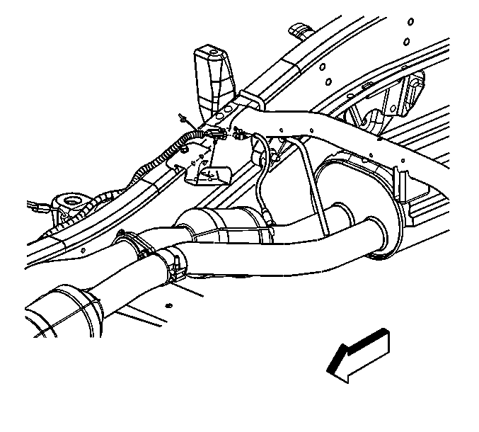
- Unclip the oxygen sensor connector from
the support.
- Disconnect the CPA retainer.
- Disconnect the oxygen sensor electrical connector.
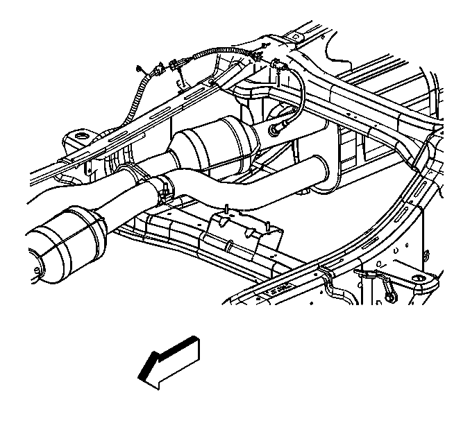
- If equipped with a 6.0L engine, perform
the following:
| • | Unclip the oxygen sensor connector from the frame. |
| • | Disconnect the CPA retainer. |
| • | Disconnect the oxygen sensor electrical connector. |
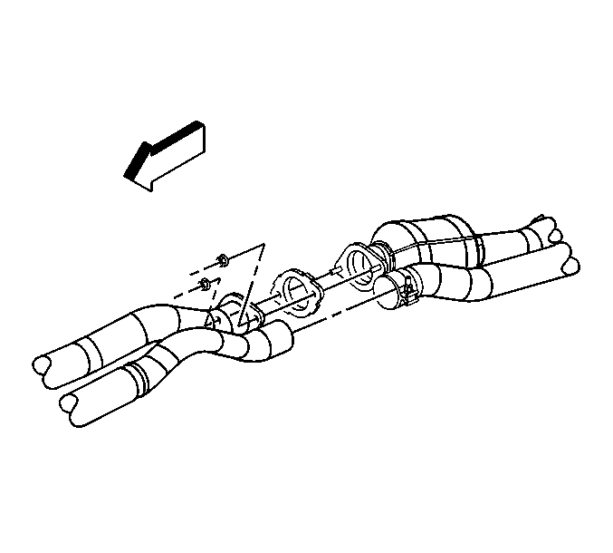
- Remove the exhaust muffler nuts.
- Loosen the exhaust pipe clamp.
- With the aid of an assistant, support the exhaust muffler.
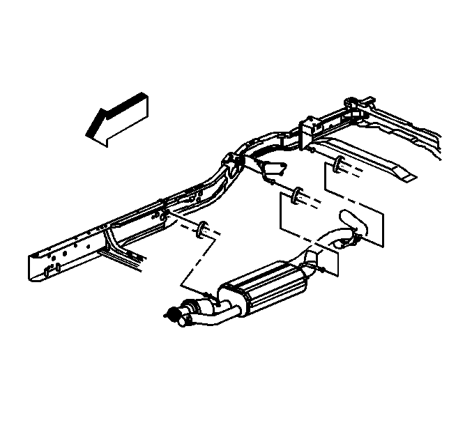
- Remove the insulators from the frame hangers.
- With the aid of an assistant, slide the muffler rearward in order to
remove the muffler from the catalytic converter.
- Remove the insulators from the muffler hangers.
- Remove the exhaust manifold pipe gasket.
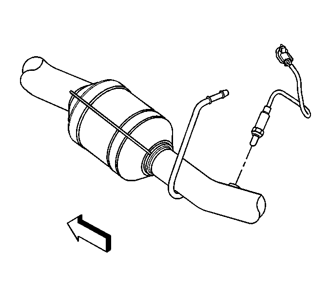
- Remove the oxygen sensor if the muffler is being replaced.
- If the muffler is NOT being replaced as an assembly, the band clamp MUST
be replaced. Perform the following:
| 20.1. | Mark the position of the band clamp on the intermediate exhaust pipe. |
| 20.2. | Remove the band clamp from the exhaust pipe by grinding the weld. |
| 20.3. | Install a NEW band clamp onto the exhaust pipe. |
Installation Procedure

- If the muffler was replaced reinstall the old oxygen sensor.
- Apply anti-seize compound GM P/N 12377953 or equivalent
to the threads of the old oxygen sensor.
Notice: Use the correct fastener in the correct location. Replacement fasteners
must be the correct part number for that application. Fasteners requiring
replacement or fasteners requiring the use of thread locking compound or sealant
are identified in the service procedure. Do not use paints, lubricants, or
corrosion inhibitors on fasteners or fastener joint surfaces unless specified.
These coatings affect fastener torque and joint clamping force and may damage
the fastener. Use the correct tightening sequence and specifications when
installing fasteners in order to avoid damage to parts and systems.
- Install the oxygen sensor.
Tighten
Tighten the oxygen sensor to 42 N·m
(31 lb ft).

Important: Apply lubricant to the insulators to aid
in installation.
- Install the insulators to the muffler hangers.
- Install a new exhaust manifold pipe gasket.
- With the aid of an assistant, slide the muffler forward in order to
install the muffler to the catalytic converter.
- Install the insulators to the frame hangers.
- Lower the vehicle.

- Position the NEW band clamp on the intermediate
exhaust pipe, using the alignment mark created previously. The band clamp bolt must
NOT be positioned below the exhaust pipe.
- Install the exhaust muffler nuts, until snug.
- Tighten the exhaust pipe clamp bolt and muffler nuts.
Tighten
| • | Tighten the nuts to 40 N·m (30 lb ft). |
| • | Tighten the clamp to 44 N·m (33 lb ft). |

- If equipped with a 6.0L engine, perform
the following:
| • | Connect the oxygen sensor electrical connector. |
| • | Connect the CPA retainer. |
| • | Clip the oxygen sensor connector to the frame. |

- Connect the oxygen sensor electrical connector.
- Connect the CPA retainer.
- Clip the oxygen sensor connector to the support.

- Connect the oxygen sensor electrical connector.
- Connect the CPA retainer.
- Clip the oxygen sensor connector to the support.

- Connect the oxygen sensor electrical connector.
- Connect the CPA retainer.
- Clip the oxygen sensor connector to the frame.


