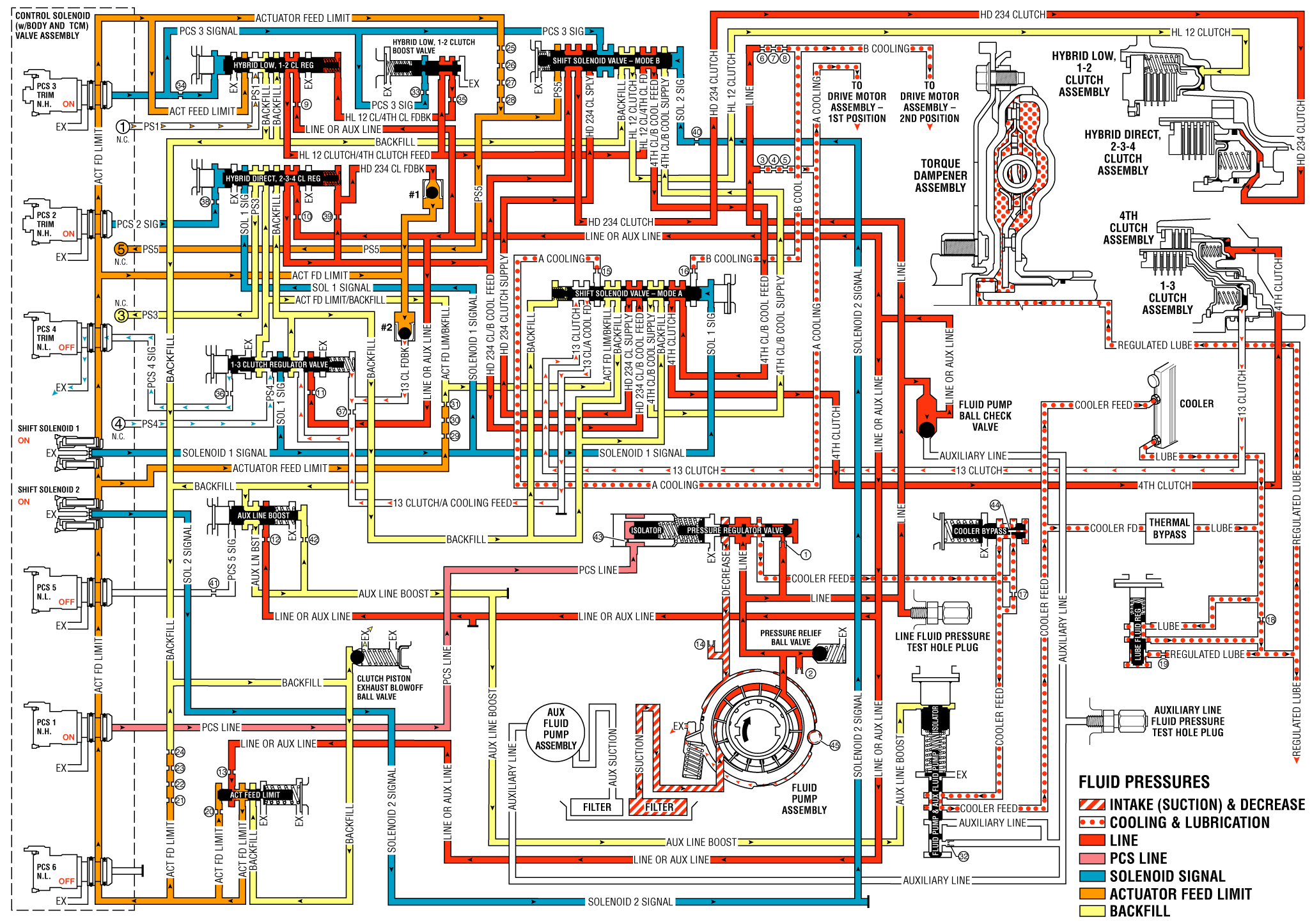
As vehicle speed increases, the TCM processes input signals from the input and output speed sensors, the TP sensor and other vehicle sensors to determine the precise moment to command ON the normally high pressure control solenoid 3 trim to regulate 4th clutch apply. At the same time, the normally low pressure control solenoid 4 trim is commanded OFF and the transmission shifts into Fourth gear.
4th Clutch Applies
Pressure Control (PC) Solenoid 3 Trim
The PC solenoid 3 trim is energized (ON) allowing actuator feed limit fluid to enter the PCS 3 signal circuit. PCS 3 signal fluid is then routed through orifice #34 to the hybrid low, 1-2 clutch regulator valve; through orifice #33 to the hybrid low, 1-2 clutch boost valve; and to the shift solenoid valve - mode B.
Hybrid Low, 1-2 Clutch Regulator Valve
PCS 3 signal fluid, at the hybrid low, 1-2 clutch regulator valve, opposes hybrid low, 1-2 clutch regulator valve spring force and HL 12 clutch/4th clutch feedback fluid pressure to regulate line or auxiliary line pressure into the HL 12 clutch/4th clutch feed circuit.
Hybrid Low, 1-2 Clutch Boost Valve
PCS 3 signal fluid pressure acts on a differential area of the hybrid low, 1-2 clutch boost valve, moving the valve against hybrid low, 1-2 clutch boost valve spring force to regulate HL 12 clutch/4th clutch feed fluid into the HL 12 clutch/4th clutch feedback circuit. As PCS 3 signal fluid pressure is increased to a given value, the hybrid low, 1-2 clutch boost valve opens the HL 1-2 clutch/4th clutch feedback circuit to exhaust. This results in the hybrid low, 1-2 clutch regulator valve moving to the full feed position, sending full HL 12 clutch/4th clutch feed pressure (full line pressure) to the hybrid low, 1-2 clutch.
Shift Solenoid - Mode B
HL 12 clutch/4th clutch feed fluid is routed to the shift solenoid valve - mode B, where it passes through the valve into the 4th clutch/B cooling feed circuit.
Shift Solenoid Valve - Mode A
4th clutch/B cooling feed fluid is routed to the shift solenoid valve - mode A, where it passes through the valve into the 4th clutch circuit.
4th Clutch Assembly
4th clutch fluid pressure enters the case assembly behind the 4th clutch piston and moves the piston against spring force to apply the 4th clutch plates.
1-3 Clutch Releases
Pressure Control (PC) Solenoid 4 Trim
The PC solenoid 4 trim is commanded OFF, allowing PCS 4 signal fluid to exhaust from the 1-3 clutch regulator valve.
1-3 Clutch Assembly
13 clutch fluid pressure is exhausted from the center support assembly, allowing 1-3 clutch spring force to move the 1-3 clutch piston and release the 1-3 clutch plates.
Shift Solenoid Valve - Mode A
Exhausting 13 clutch fluid pressure passes through the shift solenoid valve - mode A into the 13 clutch/A cooling feed circuit.
#2 Encapsulated Ball Check Valve
13 clutch feedback fluid pressure exhausts into the 13 clutch/A cooling feed circuit, allowing actuator feed limit fluid to seat the ball.
1-3 Clutch Regulator Valve
1-3 clutch regulator valve spring force moves the 1-3 clutch regulator valve to the released position, allowing 13 clutch/A cooling feed fluid pressure to exhaust through the valve in the backfill circuit.
Clutch Piston Exhaust Blowoff Ball Valve
Excess fluid pressure in the backfill circuit exhausts at the clutch piston exhaust blowoff ball valve in order to maintain a constant backfill fluid pressure of 2 psi.
Drive Range - Fourth Gear

