Removal Procedure
Warning: Refer to Brake Fluid Irritant Warning in the Preface section.
Caution: Refer to Brake Fluid Effects on Paint and Electrical Components Caution in the Preface section.
- Turn the ignition to OFF, without pausing at ACCESSORY, and remove the ignition key.
- Wait approximately 1 to 3 minutes until the brake modulator and HPA pressure relief is complete.
- Remove the brake fluid from the brake master cylinder reservoir until the level is below the reservoir supply hose fitting and discard into an approved container.
- Disconnect the brake fluid level sensor electrical connector.
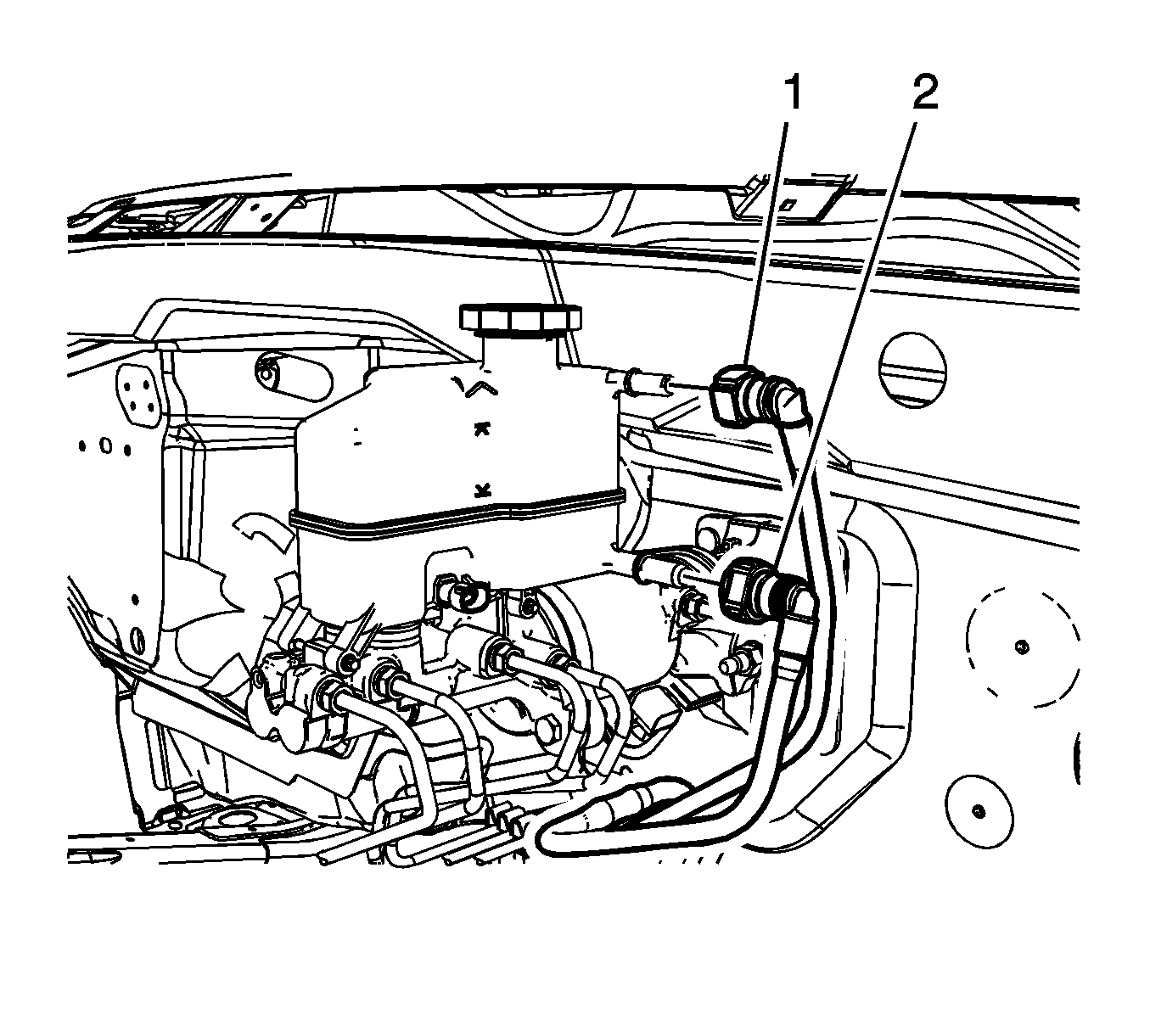
- Disconnect the brake master cylinder reservoir return hose quick connect (1).
- Disconnect the brake master cylinder reservoir supply hose quick connect (2).
- Raise and support the vehicle. Refer to Lifting and Jacking the Vehicle.
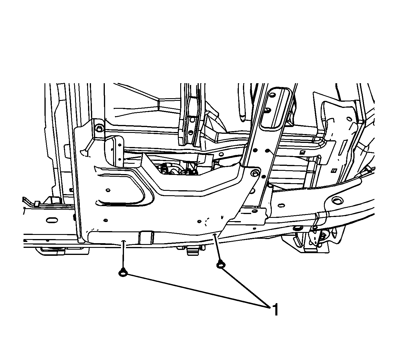
- Remove the antilock brake system (ABS) module splash shield retainers (1).
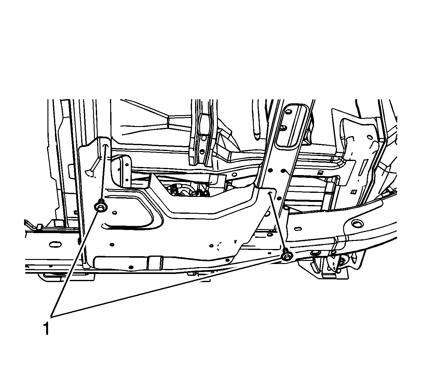
- Remove the ABS module splash shield bolts (1).
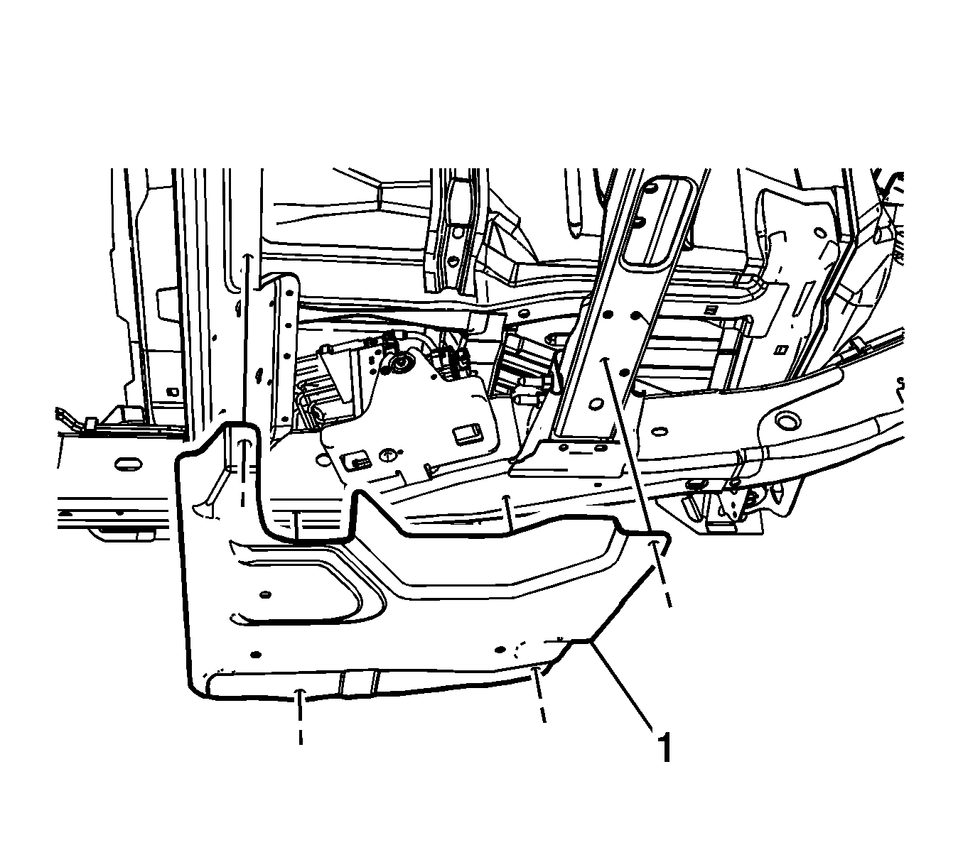
- Remove the ABS module splash shield (1).
- Clean all dirt and debris from the brake pressure modulator valve (BPMV) assembly and the brake hose fittings.
- Disconnect the BPMV supply hose quick connect (1).
- Disconnect the BPMV return hose quick connect (1).
- Release the supply and return hoses from the retainers and remove the hoses from the vehicle.
Note: The ignition must be in the OFF position, without pausing at ACCESSORY, and without applying the brake pedal to ensure the brake modulator and high pressure accumulator (HPA) pressure relief occurs. This process will take approximately 1 to 3 minutes.
Note: During the pressure relief process, the fluid level in the master cylinder reservoir will rise. Do not remove the master cylinder reservoir cap during the pressure relief process.
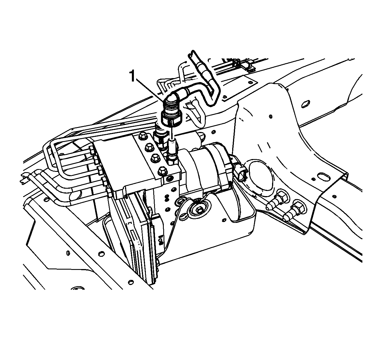
Cap the BPMV inlet port and plug the supply hose to prevent brake fluid loss and contamination.
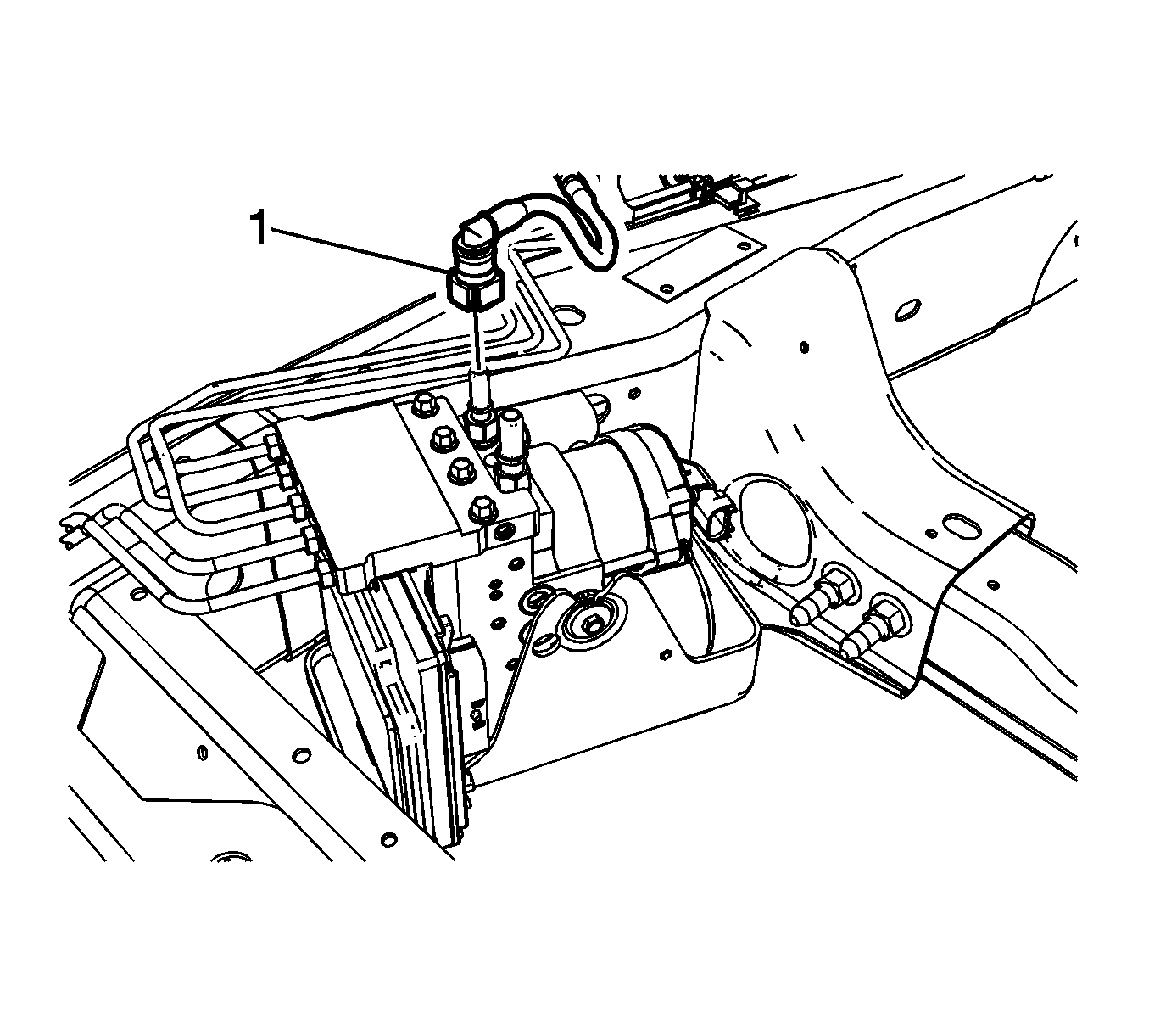
Cap the BPMV outlet port and plug the return hose to prevent brake fluid loss and contamination.
Installation Procedure
- Install the supply and return hoses to the vehicle and the retainers.
- Connect the BPMV return hose quick connect (1).
- Connect the BPMV supply hose quick connect (1).
- Install the ABS module splash shield (1).
- Install the ABS module splash shield bolts (1) and tighten to 20 N·m (15 lb ft).
- Install the ABS module splash shield retainers (1).
- Lower the vehicle.
- Connect the brake master cylinder reservoir return hose quick connect (1).
- Connect the brake master cylinder reservoir supply hose quick connect (2).
- Fill the brake master cylinder reservoir. Refer to Master Cylinder Reservoir Filling.

Ensure the return hose quick connect is fully engaged by attempting to pull the return hose from the outlet fitting.

Ensure the supply hose quick connect is fully engaged by attempting to pull the supply hose from the inlet fitting.

Caution: Refer to Fastener Caution in the Preface section.


