For 1990-2009 cars only
Removal Procedure
Note: The following service procedure includes the removal of the front park brake cable. The front park brake cable is NOT serviced separately, but serviced with the park brake pedal assembly.
- Remove the left side hinge pillar trim panel. Refer to Body Hinge Pillar Trim Panel Replacement.
- Disconnect the park brake warning lamp electrical connector.
- Disable the park brake cable automatic adjuster. Refer to Parking Brake Cable Adjuster Disabling.
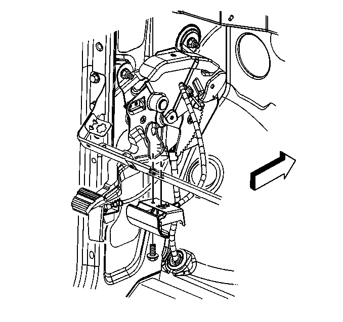
- Remove the bolt and disconnect the park brake pedal release handle from the instrument panel.
- Without disconnecting the electrical connectors, remove the left side instrument panel electrical center/junction block and position aside. Refer to Instrument Panel Electrical Center or Junction Block Replacement - Left Side.
- Raise and support the vehicle. Refer to Lifting and Jacking the Vehicle.
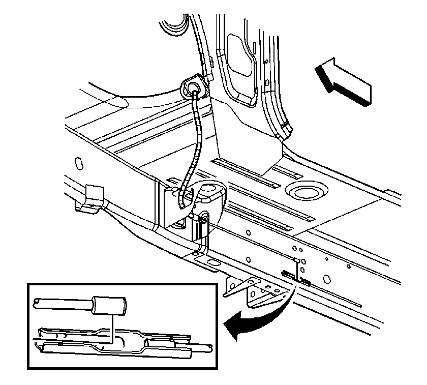
- Disconnect the front park brake cable from the intermediate cable connector by drilling a 3 mm (1/8 in) hole through the dimple in the front to intermediate park brake cable connector.
- Release the front park brake cable from the frame by depressing the locking tabs.
- Lower the vehicle.
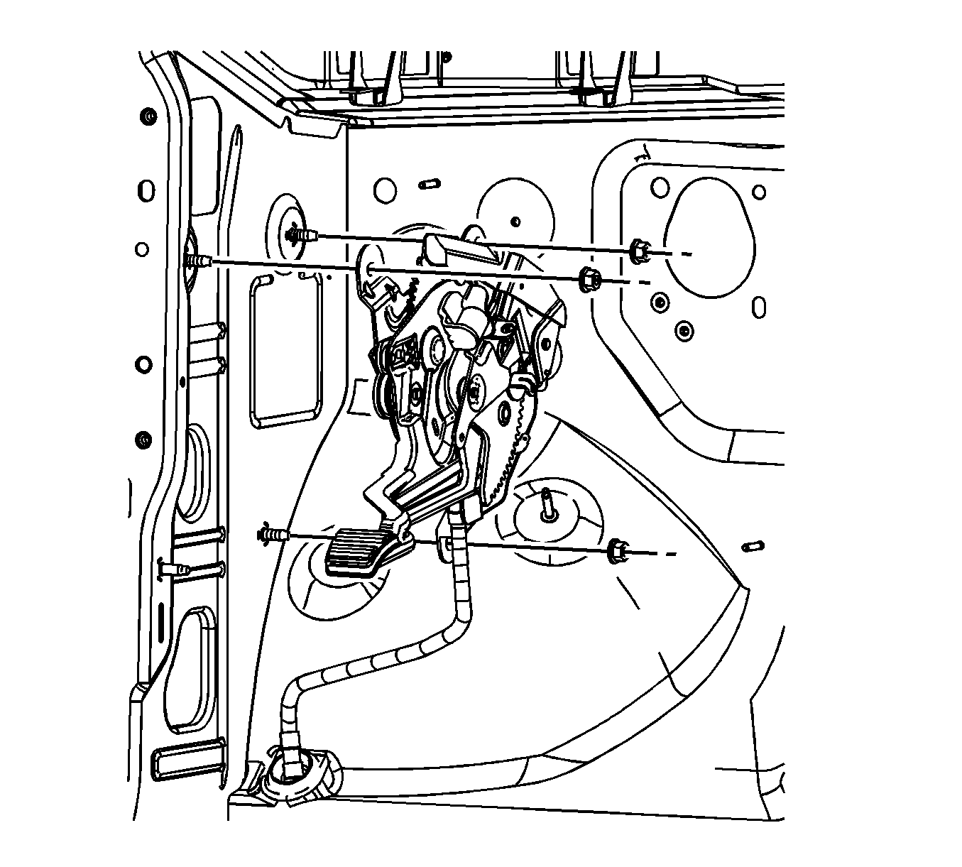
- Remove the park brake lever mounting nuts.
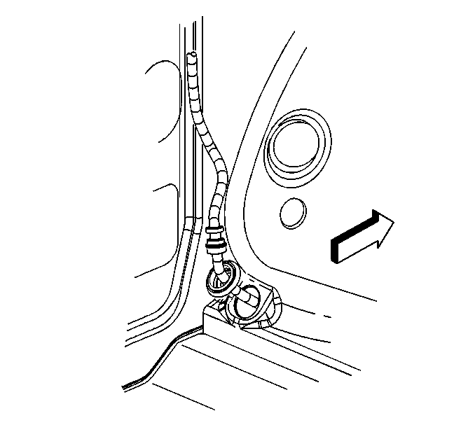
- Position the floor carpet to expose the park brake cable pass-through grommet.
- Release the park brake cable pass-through grommet from the vehicle floor.
- Remove the park brake lever and front cable from the vehicle.


Installation Procedure
- Insert the front brake cable through the hole in the front floor panel and seat the pass-through grommet.
- Position the floor carpet to the floor pan.
- Position the park brake pedal assembly on the side panel.
- Install and finger tighten the mounting nuts. Tighten the nuts to 25 N·m (18 lb ft).
- Connect the park brake warning lamp connection.
- Install the park brake release handle to the instrument panel.
- Install the park brake release handle bolt and tighten to 9 N·m (80 lb in).
- Install the hinge pillar trim panel. Refer to Body Hinge Pillar Trim Panel Replacement.
- Install the left side instrument panel electrical center/junction block. Refer to Instrument Panel Electrical Center or Junction Block Replacement - Left Side.
- Raise the vehicle.
- Install the front park brake cable to the frame and press the retainer into place.
- Connect the front park brake cable to the front to intermediate park brake cable connector.
- Lower the vehicle.
- Enable the park brake cable automatic adjuster. Refer to Parking Brake Cable Adjuster Enabling.
- Adjust the park brake. Refer to Park Brake Adjustment.

Note: Ensure the grommet for the front park brake cable is properly seated in the front floor panel.

Caution: Refer to Fastener Caution in the Preface section.


