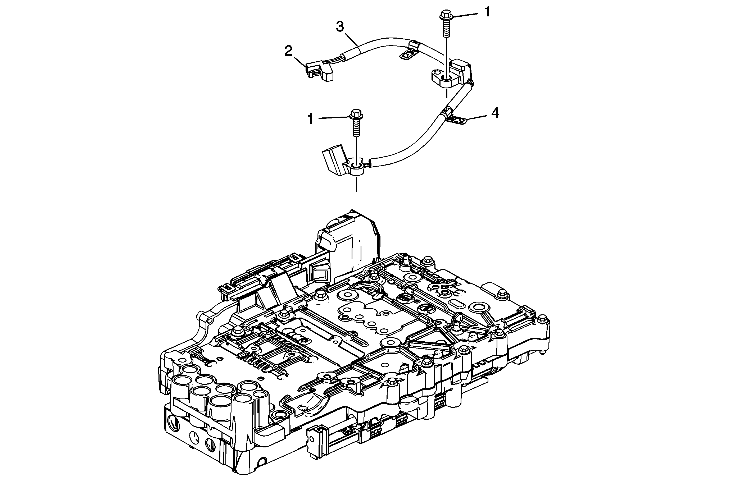
Input and Output Speed Sensor Assembly Removal

Callout | Component Name |
|---|---|
1 | Bolt M6 x 20 (Qty: 2) |
2 | Speed Sensor Electrical Connector Tip |
3 | A/Trans Input and Output Speed Sensor Assembly |
4 | A/Trans Input and Output Speed Sensor Wiring Harness Clip (Qty: 2) Tip |
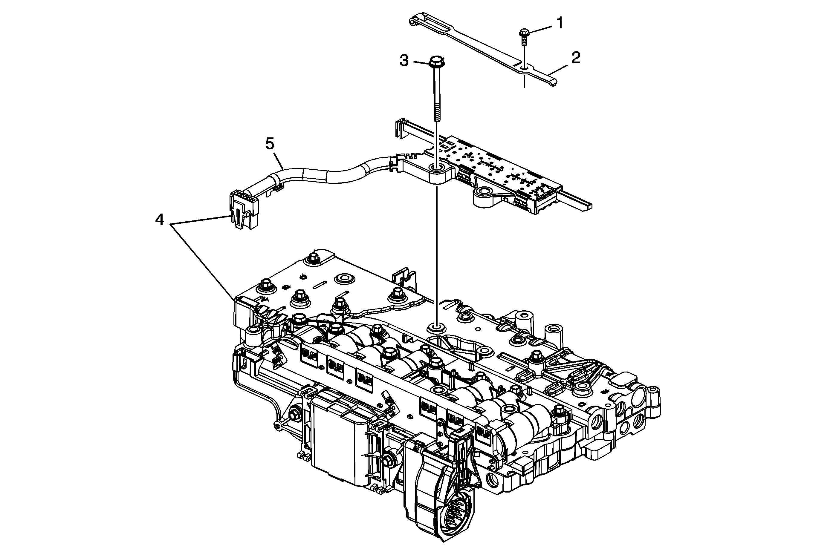
Manual Shaft Detent Assembly and Manual Shift Shaft Position Switch Removal

Callout | Component Name |
|---|---|
1 | Bolt M6 x 14.5 |
2 | Manual Shaft Detent Assembly |
3 | Bolt M5 x 55 |
4 | A/Trans Manual Shift Shaft Position Switch Assembly Electrical Connector Tip |
5 | A/Trans Manual Shift Shaft Position Switch Assembly |
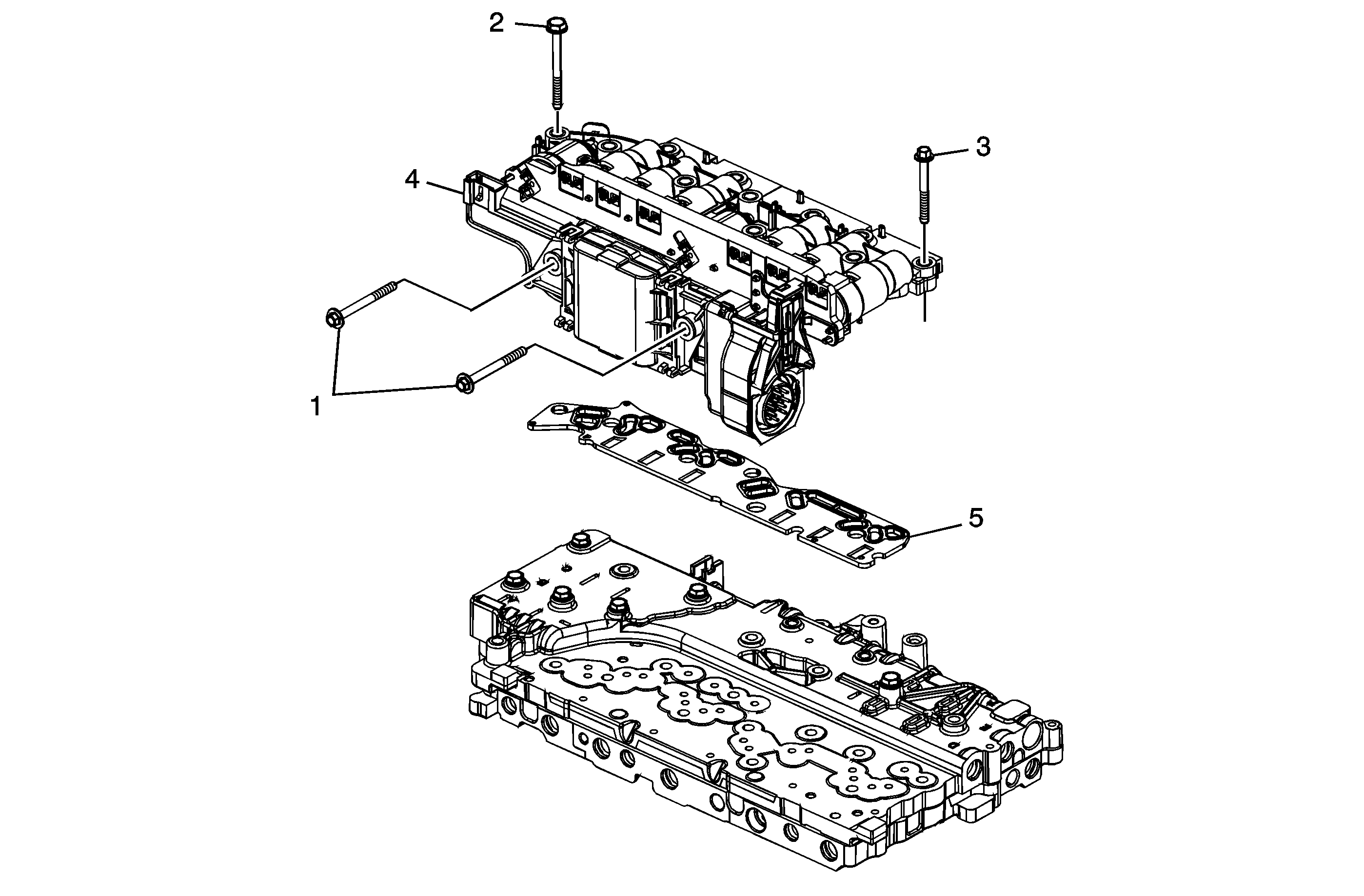
Control Solenoid Valve Assembly Removal

Callout | Component Name |
|---|---|
1 | Bolt M5 x 53 (Qty: 2) |
2 | Bolt M5 x 55 (Qty: 4) |
3 | Bolt M5 x 45 (Qty: 5) |
4 | Control Solenoid (w/Body and TCM) Valve Assembly Caution: Use care when handling the control valve body assembly. If dropped, damage to the control solenoid valve body assembly internal components, including the transmission control module (TCM), may result. |
5 | Filter Plate Assembly Caution: Use care when removing or installing the filter plate assembly. A broken or missing retaining tab may not adequately secure the filter plate to the control solenoid valve assembly, resulting in possible damage or contamination. Caution: Discard the filter plate. Replace with a NEW filter plate. Reusing an old filter plate may cause damage to the control solenoid valve assembly. |
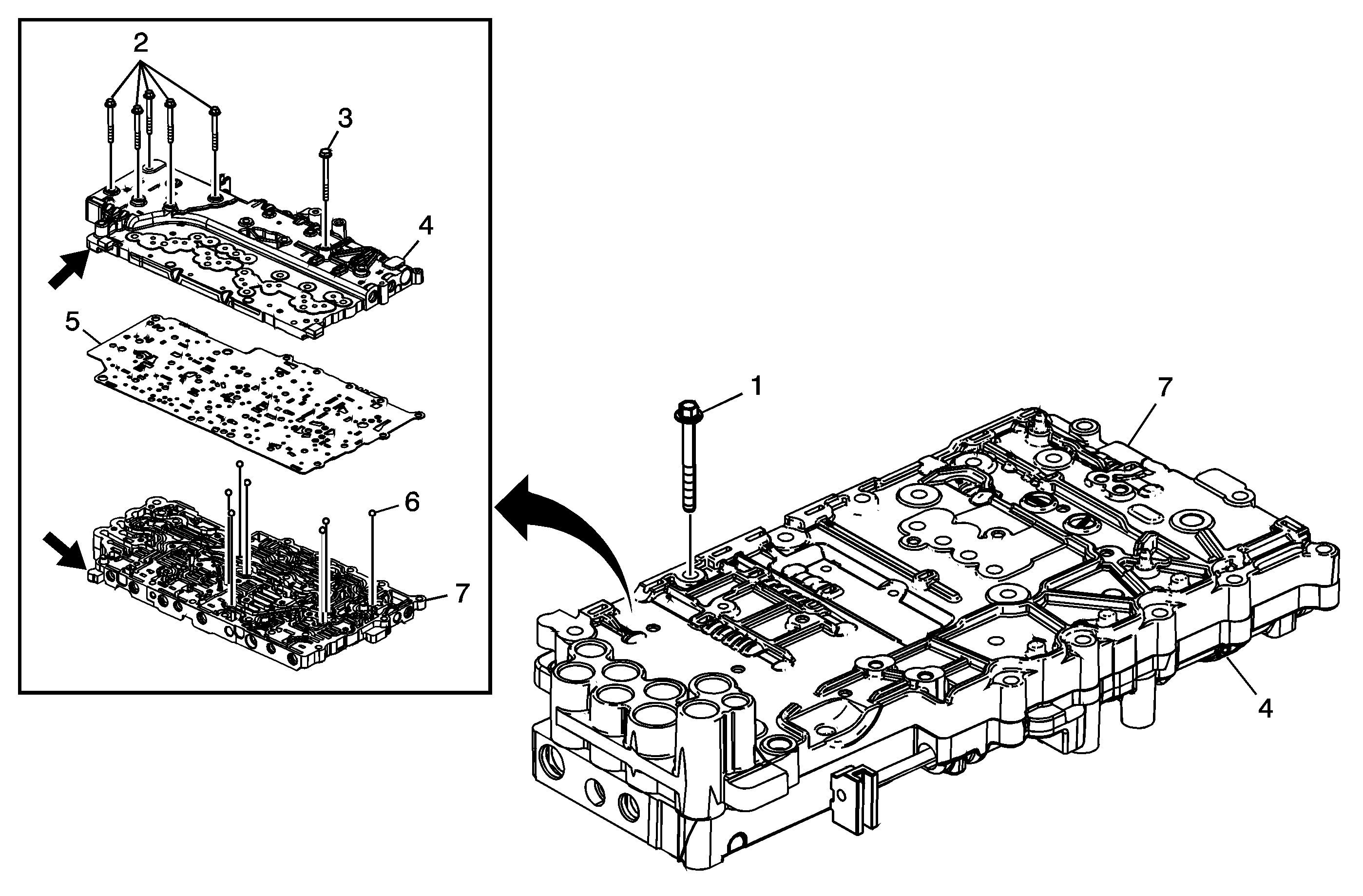
Upper and Lower Valve Bodies Disassemble

Callout | Component Name | ||
|---|---|---|---|
1 | Bolt M5 x 36 (Qty: 12) | ||
2 | Bolt M5 x 45 (Qty: 5) | ||
3 | Bolt M5 x 55 | ||
4 | Control Valve Lower Body Assembly Tip
| ||
5 | Control Valve Body Spacer (w/Gasket) Plate Assembly Caution: Do not use the old spacer plate. Install a NEW spacer plate. Reusing an old spacer plate may cause internal transmission leaks and transmission damage. | ||
6 | Control Valve Body Ball Check Valve (Qty: 7) Tip | ||
7 | Control Valve Upper Body Assembly Tip |
