For 1990-2009 cars only
Tools Required
J 26900-5 Vernier Caliper
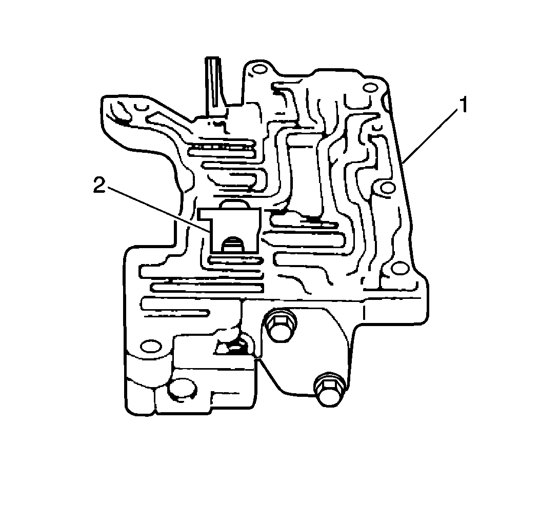
- Remove the throttle valve keep plate (2) from the valve body (1).
- Perform the following steps in order to remove the cut back valve and components:
- Remove one of the front valve body end cover pressure relief valve bolts.
- Loosen the other front valve body end cover bolt.
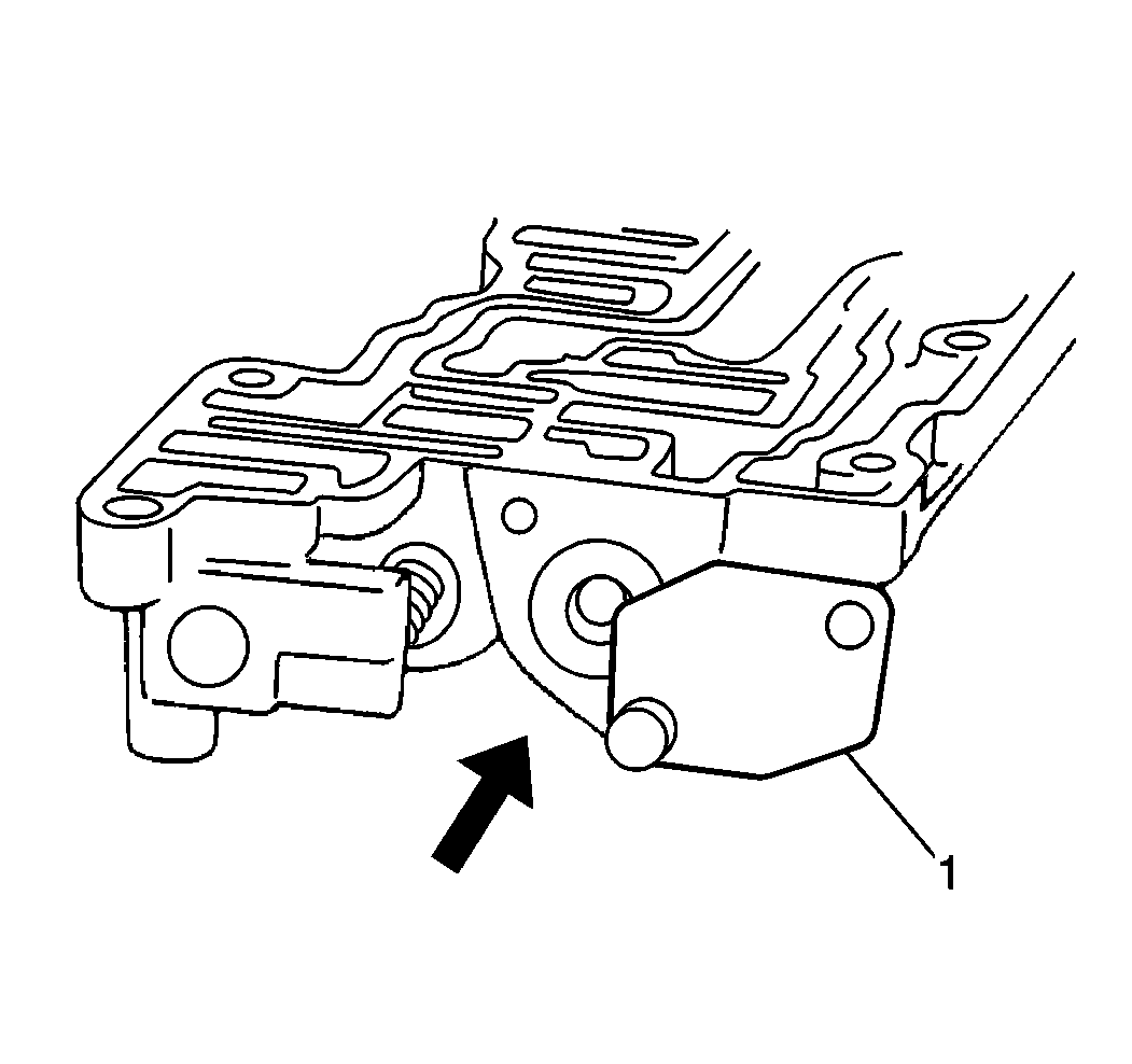
- Move the end cover away (1).
- Remove the secondary regulator valve sub assembly.
- Remove the secondary regulator valve spring.
- Remove the second front valve body end cover pressure relief valve bolt.
- Remove the end cover.
- Remove the following TV cable cam components:
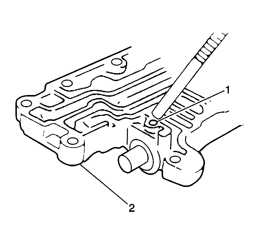
- Slightly push in the throttle valve while removing the locating pin from the down shift plug using a magnet (1).
- Remove the following throttle valve components from the valve body:
- Clean all of the upper valve body components.
- Allow the components to air dry.
- Inspect all of the valves for cracks, scoring, or other damage. Replace as necessary.
- Inspect all of the valve springs for distortion or other damage. Replace as necessary.
- Inspect the valve bores for scoring or cracks. Replace as necessary.
- Inspect the free length and outer coil diameter of all of the front upper valve body springs using the J 26900-5 .
- If the measurements do not fall within specifications, replace the springs as necessary. Refer to the General Specifications for Front Upper Valve Body Spring Specifications.
Important: When disassembling the valve body halves, keep all valve springs, spring seats and plugs within their respective valves. Most valve springs are of different sizes and CANNOT be interchanged. Verify that all parts are clean and dry before assembly.
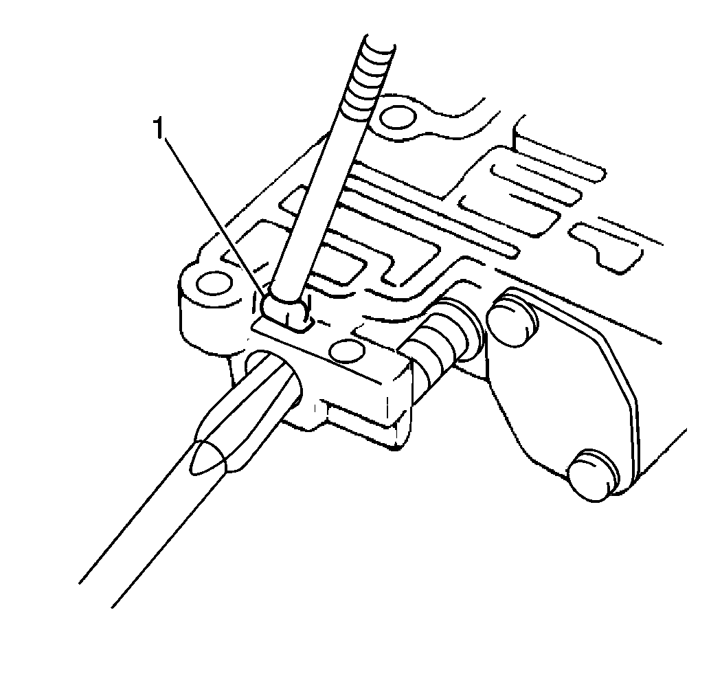
| 2.1. | Hold the cut back valve plug using a flathead screwdriver. |
| 2.2. | Remove the cut back retainer using a magnet (1). |
| 2.3. | Remove the cut back plug. |
| 2.4. | Remove the cut back valve. |
| 2.5. | Remove the cut back valve spring. |
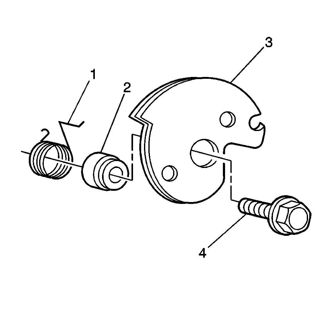
| • | The bolt (4) |
| • | The cam (3) |
| • | The return spring (1) |
| • | The spacer (2) |
Important: Note the number of throttle valve compensating rings before removal. The number of rings determines the transmission line pressure. Install the same number of rings that are removed in order to ensure the proper transmission line pressure. Some valve bodies do not require these rings.
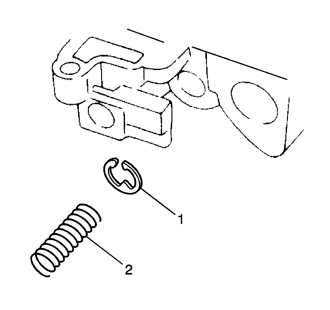
| • | The down shift plug |
| • | The throttle valve primary spring (2) |
| • | The throttle valve |
| • | The secondary valve spring |
| • | The throttle valve compensating ring(s) (1) |
