For 1990-2009 cars only
Removal Procedure
Caution: Refer to Brake Fluid Irritant Caution in the Preface section.
Notice: Refer to Brake Fluid Effects on Paint and Electrical Components Notice in the Preface section.
- Turn the ignition to OFF, without pausing at ACCESSORY, and remove the ignition key.
- Raise and support the vehicle. Refer to Lifting and Jacking the Vehicle.
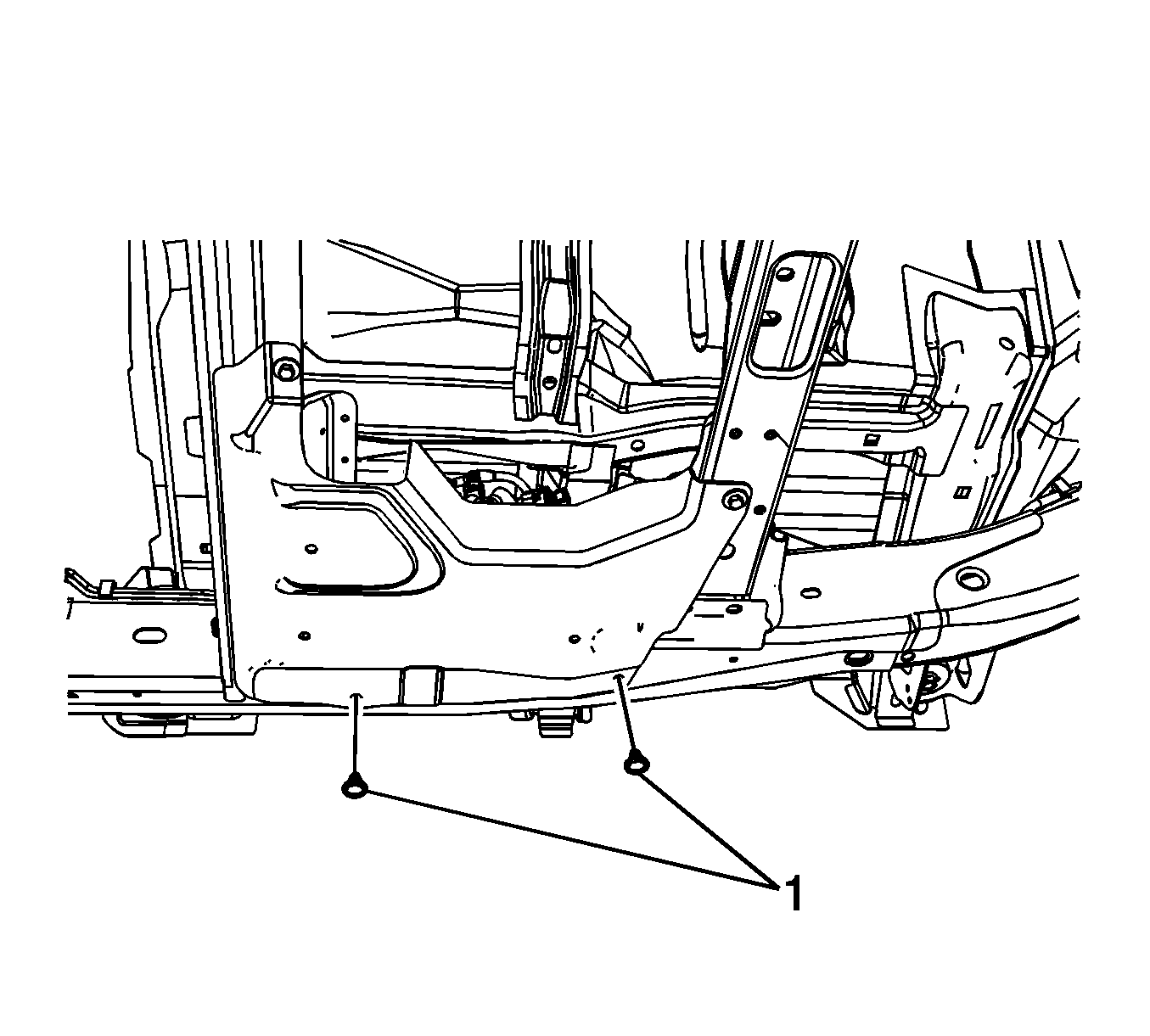
- Remove the antilock brake system (ABS) module splash shield retainers (1).
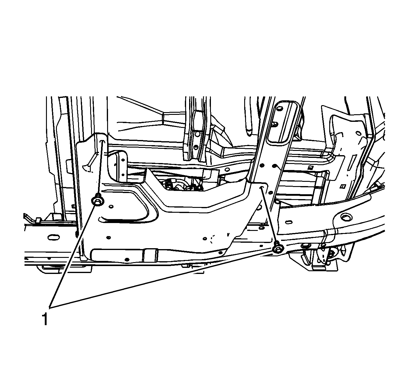
- Remove the ABS module splash shield bolts (1).
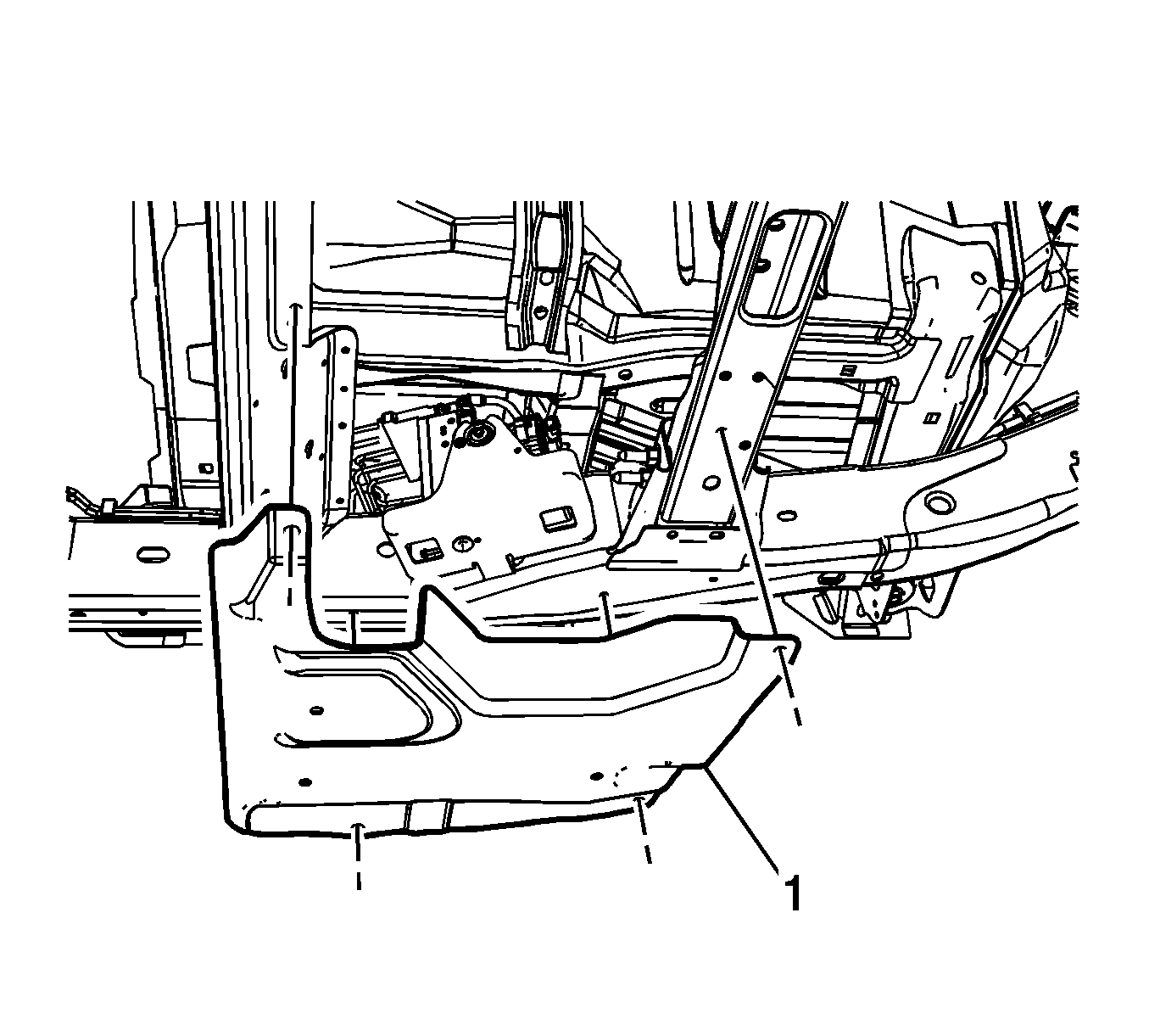
- Remove the ABS module splash shield (1).
- Clean any dirt and debris from the area around the electronic brake control position sensor.
- Disconnect the electronic brake control position sensor electrical connector.
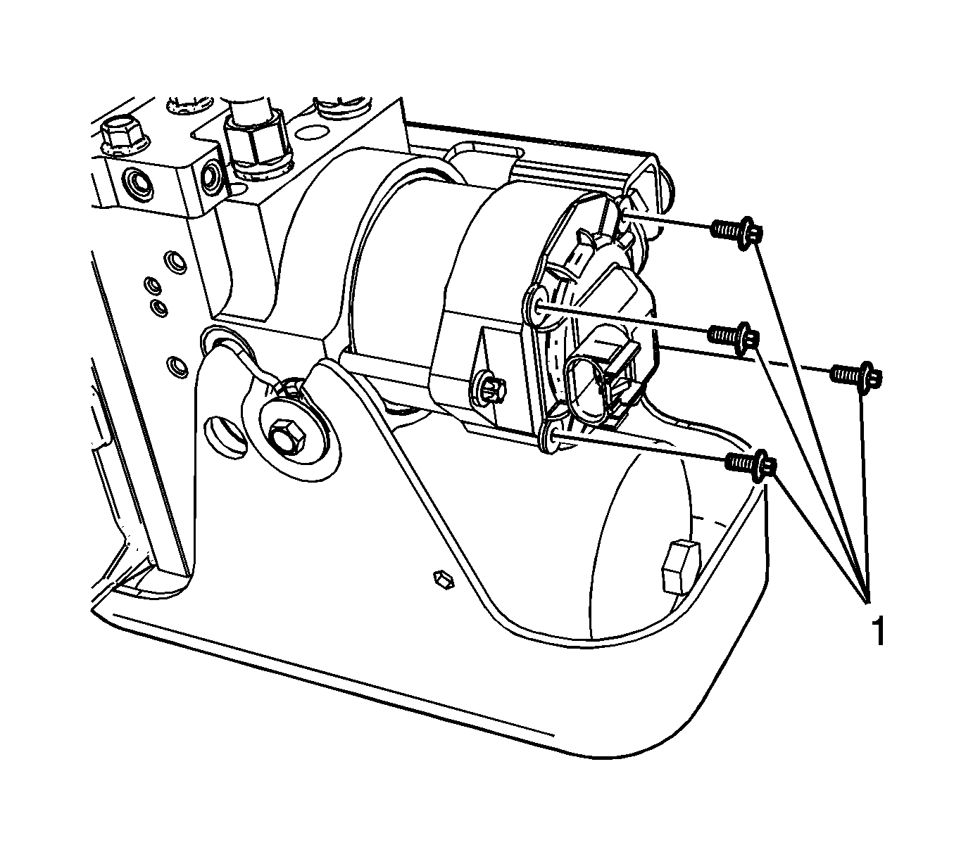
- Remove the electronic brake control position sensor bolts (1).
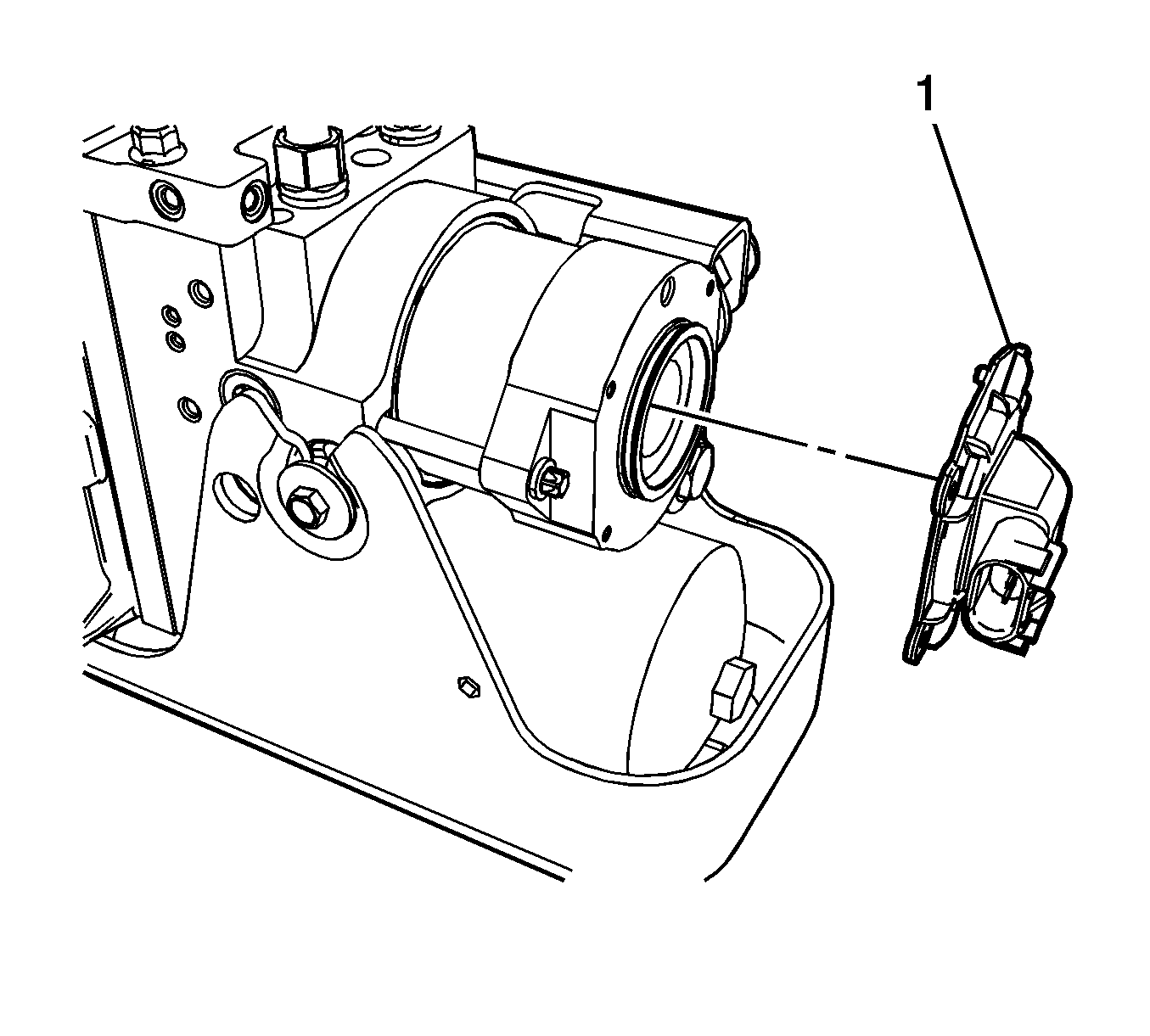
- Remove the electronic brake control position sensor (1).
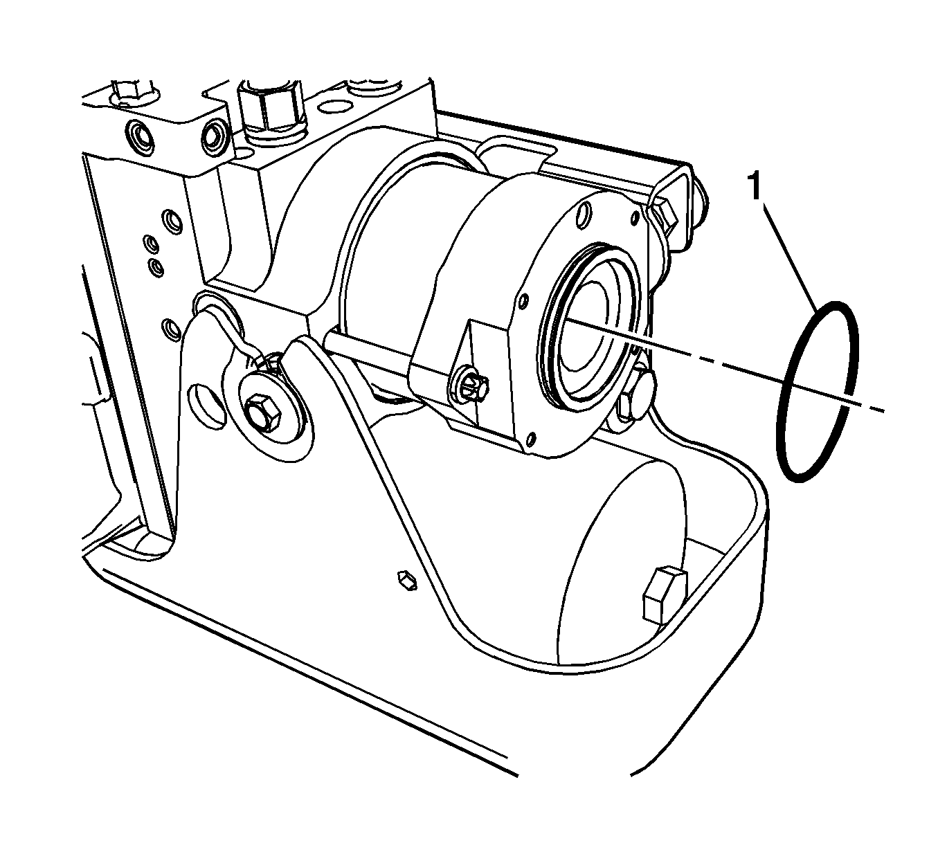
- Remove and discard the electronic brake control position sensor O-ring seal (1).
- Remove any debris from the O-ring seal groove in the brake modulator assembly motor with a clean, lint-free shop cloth.
Important: The ignition must be in the OFF position, without pausing at ACCESSORY, and without applying the brake pedal to ensure the brake modulator and high pressure accumulator (HPA) pressure relief occurs. This process will take approximately 1 to 3 minutes.
Installation Procedure
- Install a new O-ring seal (1) to the brake modulator assembly motor. Ensure the seal is fully seated in the groove of the brake modulator assembly motor and is not twisted.
- Install the electronic brake control position sensor (1).
- Install the electronic brake control position sensor bolts (1). Tighten the bolts in a cross pattern.
- Connect the electronic brake control position sensor electrical connector.
- Install the ABS module splash shield (1).
- Install the ABS module splash shield bolts (1).
- Install the ABS module splash shield retainers (1).
- Install a scan tool to the vehicle.
- Using the special functions menu on the scan tool, perform the electronic brake control sensor learn procedure.
- Perform the Diagnostic System Check - Vehicle.
Important: Do not lubricate the O-ring seal prior to installation to the brake modulator assembly motor.


Notice: Refer to Fastener Notice in the Preface section.

Tighten
Tighten the bolts to 2 N·m (18 lb in).


Tighten
Tighten the bolts to 20 N·m (15 lb ft).

