CODE 39 DIAGNOSIS PROCEDURE INFORMATION

MODELS AFFECTED: 1982-1984 WITH HT4100 ENGINES
This bulletin provides service information to aid in diagnosing and in repairing Torque Converter Clutch (TCC) related conditions (commonly reported as Code 39) on 1982-1984 model Cadillacs equipped with HT4100 engines.
Section I lists the names and functions of all Torque Converter Clutch Components.
Section II covers vehicle operating conditions required to Enable (allow the operation of) TCC.
Section III describes the events that take place when the TCC Applies.
Section IV describes the conditions required for the Electronic Control Module (ECM) to test for Code 39.
Section V covers Electrical and Hydraulic Diagnosis of the TCC system.
The information provided in this bulletin is intended to supplement the information that is provided in the appropriate model year Service Information Manuals.
I. Torque Converter Clutch Controls
Torque Converter Clutch engagement is controlled by several components. Some of these components are inputs to the ECM while others function from output signals to activate the converter clutch. All of these components, their locations and functions are listed below:
A. Inputs to ECM - These switches and sensors provide the ECM with current vehicle operating conditions so that it may determine when to apply the Torque Converter Clutch.
1. Throtttle Position Sensor (TPS) - Provides throttle position information (degrees of throttle angle) to the Electronic Control Module. TCC is disengaged at low throttle angles to avoid a shudder during coastdown. It is located on the right side of the throttle body.
2. Barometric Pressure Sensor (BARO) - Provides barometric (atmospheric) pressure information (measured in Kilopascals - KPA) to the Electronic Control Module. TCC is disengaged at high altitudes for improved driveability. It is located under the right side of the instrument panel.
3. Coolant Temperature Sensor (CTS) - Provides engine coolant temperature information (in degrees Celsius - C) to the Electronic Control Module. TCC engagement is delayed until the engine warms up for better cold driveability. It is located in the left front corner of the intake manifold.
4. Vehicle Speed Sensor (VSS) - Provides vehicle speed information (in Miles Per Hour - MPH) to the Electronic Control Module. TCC is only engaged at higher vehicle speeds to eliminate a chuggle that would be felt during low speed driving. It is located on the back of the speedometer.
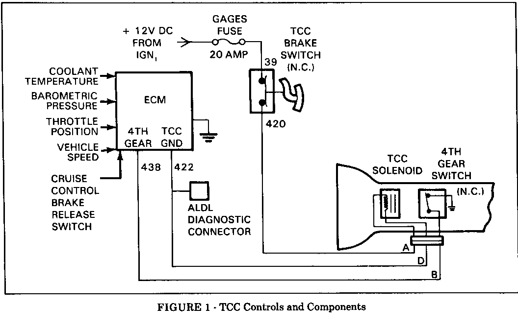
5. Fourth Gear Switch - This normally closed switch opens when in fourth gear to provide an input signal to the ECM indicating fourth gear operation. It is located near the control valve assembly.
6. TCC Brake Release Switch - This normally closed switch, located on the brake pedal bracket, opens when the brake is applied to disengage TCC. The Cruise Control brake release switch, also on the brake pedal bracket, provides an input signal to the ECM of brake operation. The switches must be adjusted so that they open at the same time.
B. Electronie Control Module (ECM) - Receives input signals and provides the ground circuit for the TCC solenoid when proper operating conditions are met. It is located under the right side of the instrument panel.
C. Outputs from ECM - These components react as a result of a command issued by the ECM.
1. TCC Solenoid -Controls the exhaust passage for converter clutch signal oil. When energized, it directs signal oil to the converter clutch apply valve causing the valve to shift and apply the TCC. It is located near the control valve assembly.
II. TCC Enable Conditions
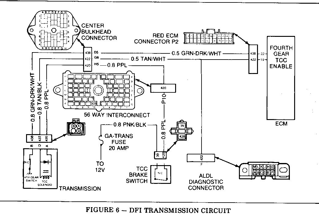
Enable conditions are those vehicle operating conditions that must be present before the ECM wiill provide the ground for the TCC solenoid. The ECM controls the apply of TCC by grounding circuit #422 (see Figure 1) which energizes the TCC solenoid, shifts the apply valve, and thereby supplies oil pressure to the Torque Converter Clutch.
ENABLE CONDITIONS
1982 1983
Throttle Angle C,E,K 6 DEG C,E,K 6-23 DEG (Parameter .0.1)* Minimum Calif. C,E,K 6-18 DEG Service PROM
BARO Above C,E,K 82 KPA C,E,K 92 KPA (Parameter .0.3)* Alt. & 2nd Gen. 79 KPA Calif. C,E,K Coolant Temp. Above C,E,K 85 DEG C Fed C,E,K 80 DEG C (Parameter .0.4 )* Calif. E,K Calif.C 74 DEG C Vehicle Speed Above C 48 MPH C 48 MPH (Parameter.1.2)* Calif.C 55 MPH Service PROM
1st Gen E,K 48 MPH E,K 53 MPH 2nd Gen E,K 53 MPH
Transmission in 4th Status Light On Status Light Gear (Hi Mode Led)* On
Time Delay After C,E,K 12 Sec. C,E,K 5 Sec. 3-4 Shift Calif. C,E,K 20 Sec. Service PROM
1984
Throttle Angle C,E,K 6-23 DEG (Parameter .0.1)* Calif. 2nd Gen. D & Calif. D,E,K 6-18 DEG Service PROM BARO Above C,E,K 92 KPA (Parameter .0.3)*
Coolant Temp. Above Fed C,E,K (Parameter .0.4 )* Calif. E,K 80 DEGC Calif. D 74 DEGC Vehicle Speed Above D 48 MPH (Parameter.1.2)* Calif. 2nd Gen. D 55 MPH
E,K 53 MPH
Transmission in 4th Status Light On Gear (Hi Mode Led)*
Time Delay After D,E,K 5 Sec. 3-4 Shift Calif. 2nd Gen. D & Calif. D,E,K 20 Sec. Service PROM
*Refer to Section 8D1 of appropriate model year Service Information Manual for information on "How To Enter Diagnostic Mode" and "Engine Data Display Procedure."
If one or more of the conditions are not met, the ECM will interrupt the ground path for the circuit causing the Torque Converter Clutch to disengage. In addition, for 1983 and 1984, if hard codes 21, 22, 24, 28, 29, 33, 35 or 36 are present, TCC will be disabled. In 1982, these codes did not disable TCC. If any of these codes are stored in memory, they must be repaired before attempting to repair a code 39.
III. TCC Operation
A. Converter Cluteh Apply Valve - Determines the method of oil feed to the torque converter to engage or disengage the clutch mechanism. The apply valve is located in the pump assembly on THM 200-4R transmissions and in the case assembly on THM 325-4L transmissions.
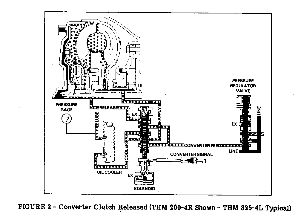
B. Converter Clutch in Released Position (refer to Figure 2) - When the TCC solenoid is not energized, converter signal oil is exhausted allowing the converter clutch apply valve spring to hold the apply valve in the release position. The apply valve in this position takes converter feed oil and sends it into the release passage, and into the cavity between the converter clutch pressure plate and the converter cover. This moves the clutch pressure plate away from the converter cover, releasing the converter clutch.
After the oil releases the converter clutch, it flows from behind the pressure plate and through the converter. From the converter, the oil flows backwards through the apply passage to the apply valve. The apply valve then sends oil, returning from the converter, to the transmission cooler in the radiator. Oil, returning from the cooler, is then directed to the transmission lubrication system.
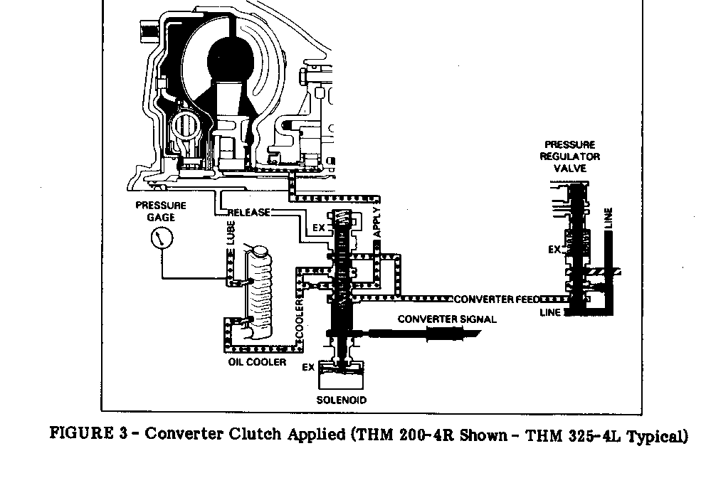
C. Converter Clutch in Applied Position (refer to Figure 3) - When enable conditions are met the ECM grounds circuit 422 and energizes the TCC solenoid. With the solenoid energized signal oil is not allowed to exhaust and overcomes the converter clutch apply valve spring, shifting the valve and changing the direction of the converter feed oil. The converter clutch apply valve will now send converter feed oil into the apply passage. The apply oil will charge the converter with oil and force the converter clutch pressure plate against the converter cover, causing a mechanical link between the engine and transmission. At the same time the converter clutch apply valve will direct some converter feed oil through an orifice to the transmission cooler in the radiator. Oil returning from the cooler, is then directed to the transmission lubrication system.
On early 1982 Cadillacs, a converter clutch shift valve and converter clutch TV valve were also in the control valve assembly. These valves were designed to control the speed at which the TCC would apply. Since TCC apply speed is controlled by the ECM on Cadillacs equipped with HT4100 engines, the converter clutch shift valve and converter clutch TV valve were no longer necessary and, therefore, eliminated. For further information regarding the elimination of these valves, refer to Serviceman Bulletin 84-25, Group 7, No. 91.
IV. Code 39 Test Conditions
Once the ECM has given an enable command to apply the TCC, the ECM will continually check vehicle speed and engine RPM to determine if the TCC is operating properly. To do so, all enable conditions must be met and vehicle speed must be between 50 and 56 MPH at a steady throttle.
When these conditions are met, the ECM will check the engine RPM. If the RPM is greater than the value shown in the table below for a period of seven seconds or more, a Code 39 will set and turn on the "Service Soon" light (for 1982 vehicles, "Check Engine" light will turn on and Cruise Control will disengage because a greater RPM indicates TCC apply has not occurred.
Standard Altitude Axle Axle ---- ---- E/K 1672 1784 C 1768 1928
If the conditions are not met, the ECM will not test for Code 39 even though an inoperative TCC condition may exist. For example, if the vehicle is being driven above 56 MPH, Code 39 will not be set even if the TCC is not able to engage. This can also make a Code 39 appear to be "intermittent" and difficult to reset, even if TCC is completely inoperative. Therefore, when testing the vehicle, it must be driven under the specific test conditions to reset a code. In addition, the ECM will not test for a Code 39 or any other code while in diagnostics.
V. TCC Diagnosis
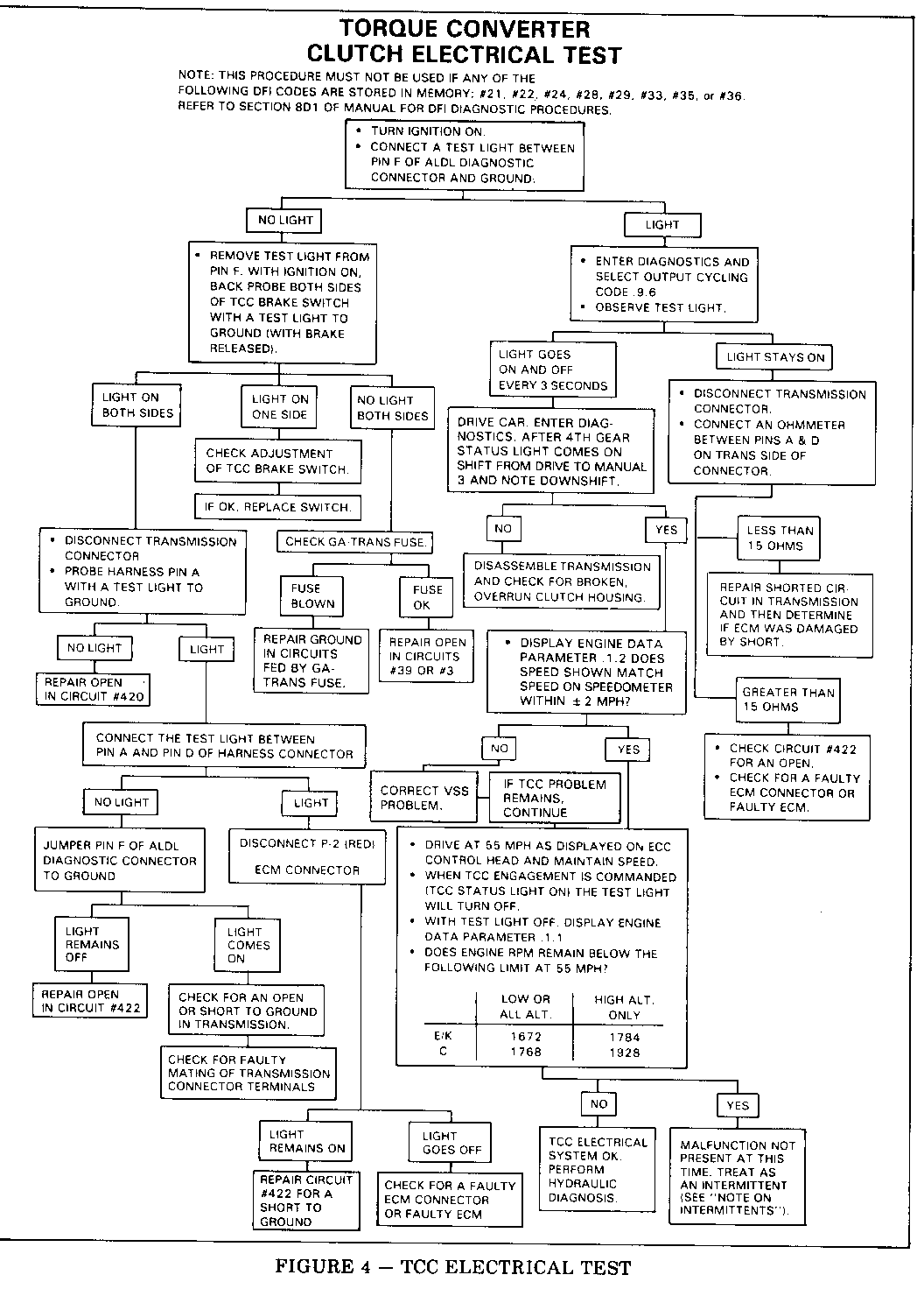
The following procedure was developed to systematically test and diagnose TCC operation and should be followed in the listed sequence to accurately diagnose this system.
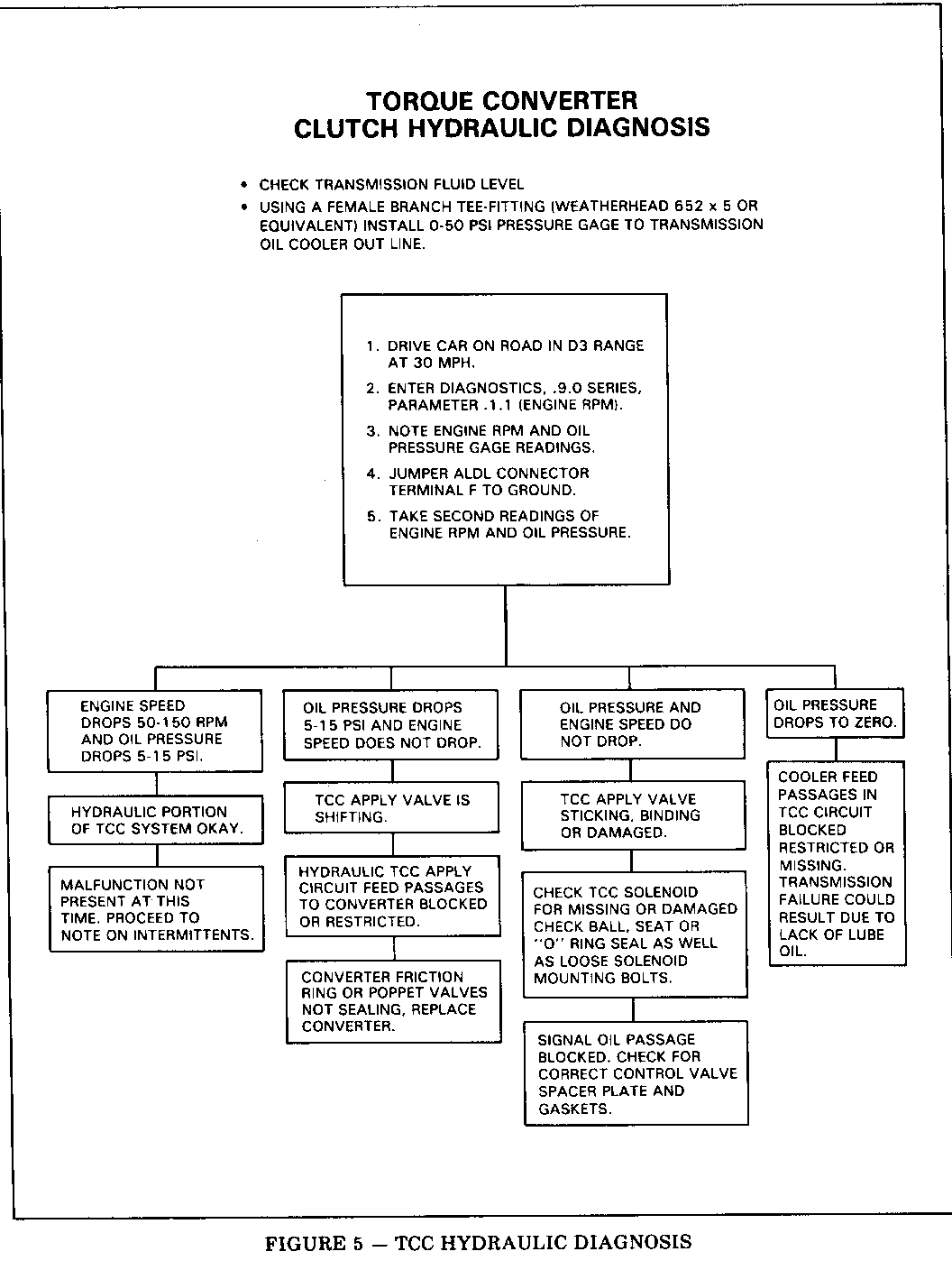
For Torque Converter Clutch diagnosis, proceed to Figure 4, TCC Electrical Test. If TCC problem remains after completing electrical test, perform Hydraulic Diagnosis, Figure 5.
On Figure 6, DFI Transmission Circuit, the center bulkhead connector shown is for 1984 vehicles only. For location of terminals and connector illustration on 1982 or 1983 vehicles, refer to the appropriate model year Service Information Manual.
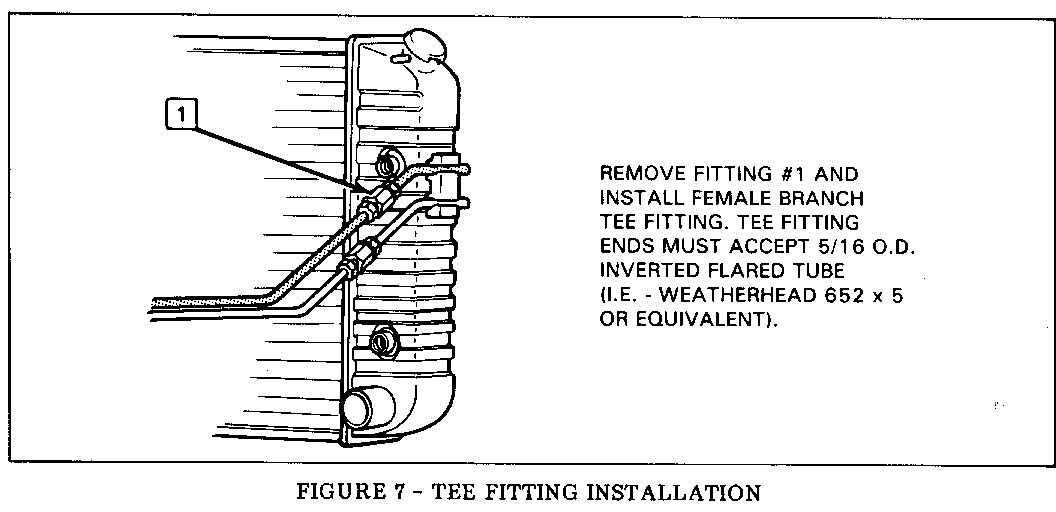
Refer to Figure 7 for Installation of Tee Fitting for hydraulic diagnosis.
NOTE ON INTERMITTENTS: If the electrical and hydraulic test procedures did not define the cause of the code 39, an intermittent electrical or hydraulic condition could exist.
ELECTRICAL INTERMITTENTS: Could be due to the adjustment of the brake switches. The ECM does not test for the TCC code if it sees the brake applied through the Cruise Control brake signal on circuit #86. This is because the TCC brake switch is also open under this condition. If the TCC brake switch is adjusted such that it opens before the Cruise Control brake release switch, a code 39 could be set if the operator were to keep the brake pedal applied just enough to open the TCC switch but not the Cruise Control switch. To check the adjustment of both switches, attach a test light from the purple wire of the TCC brake switch to ground and another test light from the dark green wire of the Cruise Control brake switch to ground. With the ignition on, both test lights should be lit. When the brake pedal is depressed 1/8" to 1/2", the test light on the Cruise Control brake release switch should turn off first followed by the light at the TCC brake switch. Intermittent electrical conditions could also be a result of poor connections or wiring intermittently shorted or open.
HYDRAULIC INTERMITTENTS: Could be due to a malfunction of one or more of the following: converter clutch apply valve, TCC solenoid, or poppet valves on converter clutch plate inside the torque converter.
General Motors bulletins are intended for use by professional technicians, not a "do-it-yourselfer". They are written to inform those technicians of conditions that may occur on some vehicles, or to provide information that could assist in the proper service of a vehicle. Properly trained technicians have the equipment, tools, safety instructions and know-how to do a job properly and safely. If a condition is described, do not assume that the bulletin applies to your vehicle, or that your vehicle will have that condition. See a General Motors dealer servicing your brand of General Motors vehicle for information on whether your vehicle may benefit from the information.
