DIESEL ENGINE SERVICE PISTONS PISTON PINS/RETAINER CHANGE

MODELS AFFECTED: 1984-1985 ELDORADO, SEVILLE, FLEETWOOD, DEVILLE AND BROUGHAM
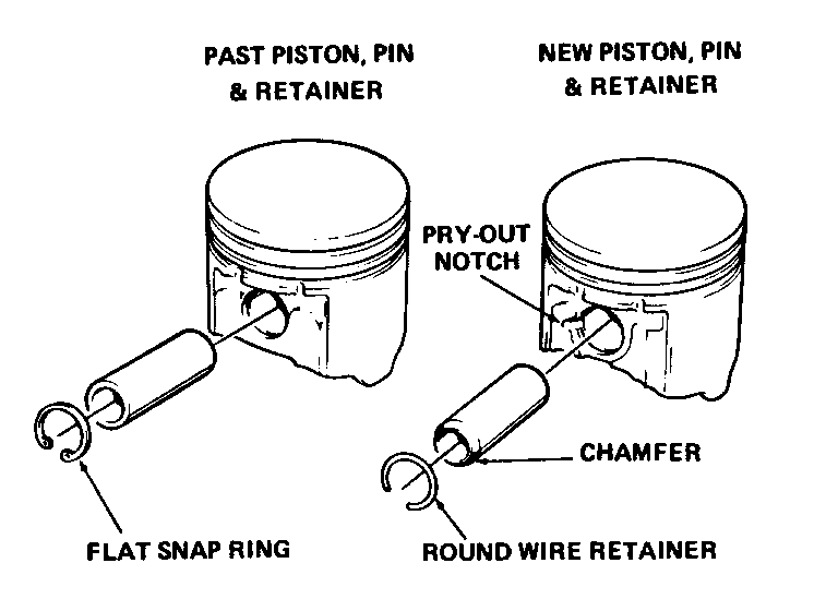
The piston pin and retainer have been changed for 1984 model diesel engines. This change utilizes a longer piston pin which is chamfered on each end, along with a round wire retaining ring. To accommodate the round wire ring, the retainer ring groove in the piston has been changed from a square cut groove to a rounded groove. It also contains a pry-out notch (see Figure 1).
Some service pistons now being used incorporate the round wire retainer. Eventually, all service pistons will. Goodwrench engines being produced now also contain the round wire ring retainer.
The service pistons used in past model engines may contain both designs of retaining rings. It is important to remember that the pistons, piston pins, and piston pin retainers MUST NOT be interchanged. Become familiar with each component. The round wire ring goes with the pin that is chamfered on each end and the piston has a pry-out notch. The flat snap ring goes with a square end piston pin and the piston does not have a pry-out notch. Procedures for removing and installing the round wire ring are as listed below:
Removal
1. Place J-34594-1 installer inside the piston pin's inside diameter. Put a shop towel over the installer; holding the installer and shop towel with one hand will retain the retainer as it is removed.
2. Place a thin bladed screw driver in the notch and carefully pry the retainer out of the piston. Repeat on the other retainer.
REMOVE ALL BURRS ON THE PISTON THAT RESULTED WHEN THE RETAINER WAS REMOVED. DO NOT REUSE THE RETAINERS.
Installation
1. Insert one end of a new retainer into the piston pin retainer bore. Position the retainer so that the gap in the retainer is in the down position (toward the connecting rod).
2. Place installer J-34594-1 into the piston pin. Rotate the installer, so that the pin that protrudes from the installer, pushes the retainer into the piston's groove.
3. Remove the installer and inspect that the retainer is fully seated and that the gap in the ring is in the down position. Correct as necessary.
4. If the retainer is not fully seated, insert tool J-34594-2 into the piston pin. Push down on the tool until the retainer is fully seated.
5. Repeat steps 1 through 4 to install the opposite snap ring.

General Motors bulletins are intended for use by professional technicians, not a "do-it-yourselfer". They are written to inform those technicians of conditions that may occur on some vehicles, or to provide information that could assist in the proper service of a vehicle. Properly trained technicians have the equipment, tools, safety instructions and know-how to do a job properly and safely. If a condition is described, do not assume that the bulletin applies to your vehicle, or that your vehicle will have that condition. See a General Motors dealer servicing your brand of General Motors vehicle for information on whether your vehicle may benefit from the information.
