A.I.R. PIPE CORROSION PRODUCTION CHANGE

MODELS AFFECTED: 1982-1983 DEVILLE, BROUGHAM, ELDORADO AND SEVILLE
Some 1982-1983 Deville, Brougham, Eldorado and Seville vehicles equipped with the HT4100 engine may experience a condition of A.I.R. pipe corrosion. In order to alleviate this corrosion potential, a mid-1983 model year production change to stainless steel pipes was initiated. This change was effective after the following 1983 VIN breakpoints:
A.I.R. Pipe to Left A.I.R. Pipe to Right Exhaust Manifold Exhaust Manifold Model (P/N 1627722) (P/N 1627723) ----- -------------- ------------- Deville/Brougham (C Series) 200639 183062 Eldorado (E Series) 636474 629155 Seville (K Series) 816762 812477
On-car service procedures for all A.I.R. system pipes (including the two mentioned above) were inadvertently not published in the 1982-1984 Service Information Manuals. If replacement of any A.I.R. system pipe is required, refer to the on-car service procedures and warranty information listed below:
WARRANTY INFORMATION HOURS Labor 82-83C 82-84 Operation 84D E/K
A.I.R. Pipe - Check Valve to Exhaust Manifold (Right) J6133 1.3 **1.1 A.I.R. Pipe - Check Valve to Exhaust Manifold (Left) J6134 *1.5 **1.1 A.I.R. Pipe - Check Valve to Exhaust Manifold (Both) J6135 *2.7 **2.0 A.I.R. Pipe - Catalytic Converter (Upper) J6102 0.4 - A.I.R. Pipe - Catalytic Converter (Lower) J6103 0.3 - A.I.R. Pipe - Catalytic Converter (One Piece) J6108 - 0.4 A.I.R. Check Valve J6086 0.2 0.2 *Increased Time **Decreased Time
The A.I.R. pipe is a 5 year/50,000 mile emission warranty item and should be replaced without cost to our customers during the 5 year/50,000 mile period.
82-83 C, E, K; 84 D, E, K ON-CAR SERVICE PROCEDURES
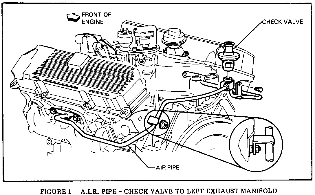
CHECK VALVE TO LEFT EXHAUST MANIFOLD A.I.R. PIPE
Removal (Figure 1)
1. Open hood and cover fenders.
2. Remove air cleaner.
3. Disconnect spark plug wires 2, 3, 4 and 8 from distributor to gain access to air pipe fitting at check valve air.
4. Disconnect pipe from check valve using an 11/16 inch open end wrench.
5. Disconnect the bracket which holds the A.I.R. pipe to the vacuum pipe at the rear of the engine using a 7mm box end wrench. Disconnect the bracket which holds the A.I.R. pipe to the vacuum pipe at the exhaust manifold using a 7mm box end wrench.
6. Remove the six 10mm hex screws which attach the heat stove to the exhaust manifold and remove the heat stove.
7. Disconnect the A.I.R. pipe from the exhaust manifold using a 13mm box end wrench.
8. (C/D SERIES ONLY) Raise vehicle.
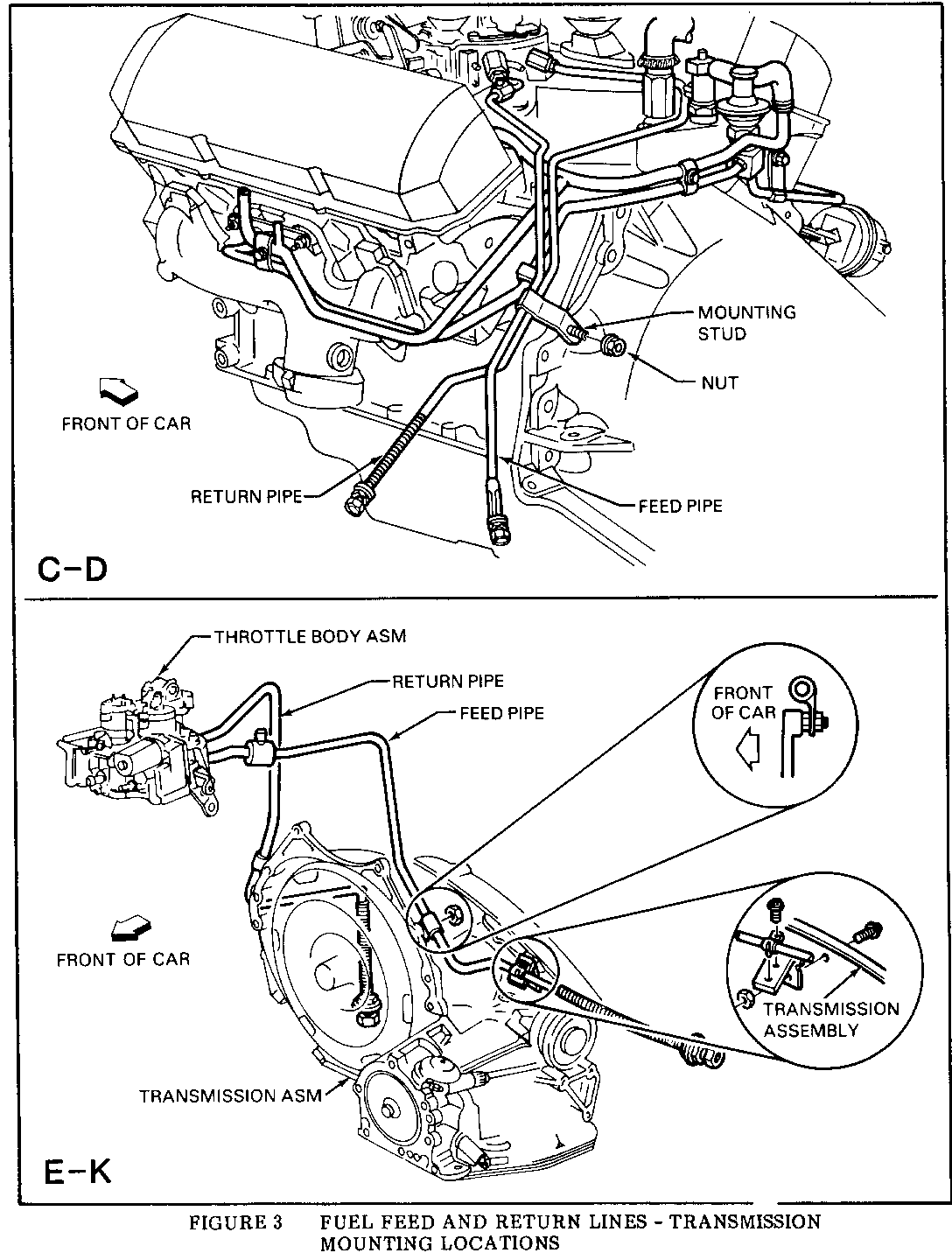
9. (C/D SERIES ONLY) Disconnect the fuel feed and return lines mounting, bracket,
Figure 3, from the transmission using a 15mm flex socket wrench with a long extension.
(E/K SERIES ONLY) Disconnect the fuel feed and return lines mounting brackets,
Figure 3, from the transmission using 13mm and 15mm socket wrenches.
10. (C/D SERIES ONLY) Disconnect the A.I.R. pipe from the cylinder head/engine lift mounting stud using a 15mm flex socket wrench with a long extension.
(E/K SERIES ONLY) Disconnect the A.I.R. pipe from the cylinder head/engine lift mounting stud using a 15mm socket wrench.
11. (C/D SERIES ONLY) Disconnect transmission and starter harnesses to provide clearance.
12. (C/D SERIES ONLY) With the pipe in its normal position, rotate the exhaust manifold end of the pipe so that it is pointed downward. Move the fuel feed and return lines so that the A.I.R. pipe is below the lines. Remove the A.I.R. pipe.
(E/K SERIES ONLY) Remove the A.I.R. pipe.
Installation (Figure 1)
1. (C/D SERIES ONLY) From the underside of the vehicle, install the A.I.R. pipe (CHECK VALVE END FIRST) so that the exhaust manifold end of the pipe points downward. When installing the pipe, make certain that it is routed on the engine side of both the fuel feed and return lines and the engine ground strap. Move the fuel feed and return lines so that the A.I.R. pipe is on the upper side of the lines. Rotate the exhaust manifold end of the pipe into its normal position.
(E/K SERIES ONLY) Install the A.I.R. pipe.
2. (C/D SERIES ONLY) Lower vehicle.
3. Connect the A.I.R. pipe to the check valve using an 11/16 inch open end wrench.
4. (C/D SERIES ONLY) Raise vehicle.
5. (C/D SERIES ONLY) Connect transmission and starter harnesses.
6. (C/D SERIES ONLY) Connect the pipe to the cylinder head/engine lift mounting stud using a 15mm flex socket wrench with a long extension.
(E/K SERIES ONLY) Connect the pipe to the cylinder head/engine lift mounting stud using a 15mm socket wrench.
7. (C/D SERIES ONLY) Connect the fuel feed and return lines mounting bracket to the transmission, Figure 3, using a 15mm flex socket wrench with a long extension.
(E/K SERIES ONLY) Connect the fuel feed and return lines mounting bracket, Figure 3, using 13mm and 15mm socket wrenches.
8. (C/D SERIES ONLY) Lower vehicle.
9. Connect the pipe to the exhaust manifold using a 13mm box end wrench.
10. Install the heat stove and attach it to the exhaust manifold using the six 10mm hex screws.
11. Connect the bracket which holds the A.I.R. pipe to the vacuum pipe at the exhaust manifold using a 7mm box end wrench.
12. Connect the bracket which holds the A.I.R. pipe to the vacuum pipe at the rear of the engine using a 7mm box end wrench.
13. Connect spark plug wires 2, 3, 4 and 8 to the distributor.
14. Install air cleaner.
15. Remove fender covers and close hood.
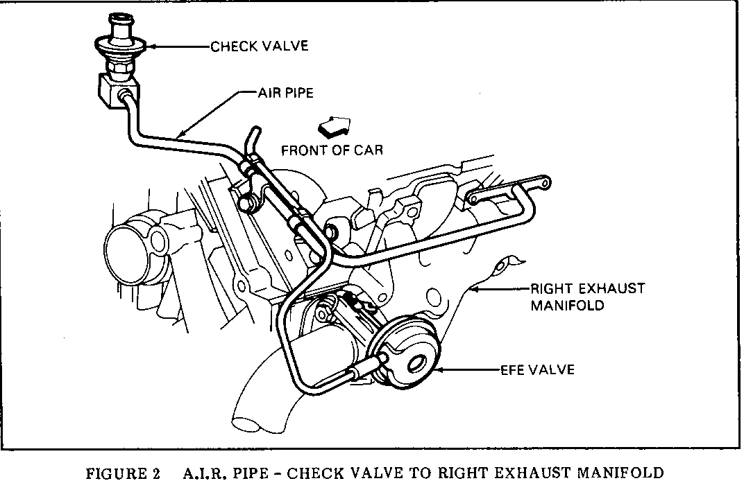
CHECK VALVE TO RIGHT EXHAUST MANEFOLD A.I.R. PIPE
Removal (Figure 2)
1. Open hood and cover fenders.
2. Remove air cleaner.
3. Remove the right sheet metal diagonal brace using a 13mm socket wrench.
4. Disconnect spark plug wires 2, 3, 4 and 8 from distributor to gain access to pipe fitting at check valve.
5. Disconnect vacuum hose from the thermal vacuum switch.
6. Disconnect pipe from check valve using an 11/16 inch open end wrench.
7. Remove A.I.R. management assembly from its mounting bracket using a 13mm socket wrench.
8. Disconnect inlet and outlet hoses and electrical connectors from the A.I.R. management assembly.
9. Remove A.I.R. management mounting bracket and electrical ground straps from the exhaust manifold using a 13mm socket wrench.
10. Remove the generator support bracket using a 13mm socket wrench.
11. Disconnect the A.I.R. pipe from the exhaust manifold using a 13mm socket wrench.
12. Remove the retaining clips which hold the A.I.R. pipe to the EFE vacuum pipe.
13. (C/D SERIES ONLY) Raise vehicle.
14. (C/D SERIES ONLY) Disconnect the A.I.R. pipe from the cylinder head mounting stud using a 15mm flex socket wrench with a long extension.
(E/K SERIES ONLY) Disconnect the A.I.R. pipe from the cylinder head mounting stud using a 15mm socket wrench.
15. (C/D SERIES ONLY) Lower vehicle.
16. Remove A.I.R. pipe.
Installation (Figure 2)
1. Install A.I.R. pipe.
2. Connect pipe to the check valve using an 11/16 inch open end wrench.
3. (C/D SEREES ONLY) Raise vehicle.
4. (C/D SERIES ONLY) Connect the A.I.R. pipe to the cylinder head mounting stud using a 15mm flex socket with a long extension.
(E/K SERIES ONLY) Connect the A.I.R. pipe to the cylinder head mounting stud using a 15mm socket wrench.
5. (C/D SERIES ONLY) Lower vehicle.
6. Install the retaining clips which hold the A.I.R. pipe to the EFE vacuum pipe.
7. Connect the A.I.R. pipe to the exhaust manifold using a 13mm socket wrench.
8. Install the generator support bracket using a 13mm socket wrench.
9. Install the A.I.R. management mounting bracket and electrical ground straps to the exhaust manifold using a 13mm socket wrench.
IMPORTANT: Improper installation of the electrical ground straps may affect vehicle performance. Special care should be taken to insure correct ground strap installation.
10. Connect inlet and outlet hoses and electrical connectors to the A.I.R. management assembly.
11. Install A.I.R. management assembly to its mounting bracket using a 13mm socket wrench.
12. Connect vacuum hose to the Thermal Vacuum Switch.
13. Connect spark plug wires 2, 3, 4 and 8 to the distributor.
14. Install the right sheet metal diagonal brace using a 13mm socket wrench.
15. Install air cleaner.
16. Remove fender covers and close hood.
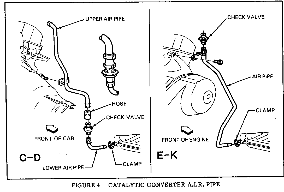
UPPER CATALYTIC CONVERTER A.I.R. PIPE (C/D SERIES) -------------------------------------------------- Removal (Figure 4)
1. Open hood and cover fenders.
2. Disconnect A.I.R. management hose at A.I.R. pipe.
3. Raise vehicle.
4. Disconnect A.I.R. hose from the upper pipe.
5. Disconnect pipe from transmission mounting stud using a 15mm socket wrench with a 3 inch extension, universal joint, and a long extension.
6. Remove the upper A.I.R. pipe.
Installation (Figure 4)
1. Install the upper A.I.R. pipe.
2. Connect pipe to transmission mounting stud using a 15mm socket wrench with a 3 inch extension, universal joint, and a long extension.
3. Connect A.I.R. hose to the upper pipe.
4. Lower vehicle.
5. Connect A.I.R. management hose to the A.I.R. pipe.
6. Remove fender covers and close hood.
LOWER CATALYTIC CONVERTER A.I.R. PIPE (C/D SERIES) -------------------------------------------------- Removal (Figure 4)
1. Raise vehicle.
2. Disconnect A.I.R. hose at check valve.
3. Remove pipe clamp and A.I.R. pipe from converter pipe.
4. Remove check valve from pipe.
Installation (Figure 4)
1. Install check valve on pipe.
2. Install A.I.R. pipe to converter pipe and install pipe clamp.
3. Connect A.I.R. hose to check valve.
4. Lower vehicle.
CATALYTIC CONVERTER A.I.R. PIPE (E/K SERIES) -------------------------------------------- Removal (Figure 4)
1. Open hood and cover fenders.
2. Disconnect A.I.R. management hose from A.I.R. check valve.
3. Disconnect A.I.R. pipe from engine mount using a 15mm socket wrench.
4. Raise vehicle.
5. Remove pipe clamp and A.I.R. pipe from catalytic converter pipe.
6. Remove A.I.R. pipe.
7. Remove A.I.R. check valve from pipe.
Installation (Figure 4)
1. Install A.I.R. check valve onto pipe.
2. Install A.I.R. pipe.
3. Install A.I.R. pipe to catalytic converter pipe and install pipe clamp.
4. Lower vehicle.
5. Connect A.I.R. pipe to engine mount using a 15mm socket wrench.
6. Connect A.I.R. management hose to A.I.R. check valve.
7. Remove fender covers and close hood.
A.I.R. CHECK VALVE ------------------
Removal
1 .Release clamp and disconnect air hoses from check valve.
2. Unscrew check valve from air injection pipe.
Installation
1. Screw check valve onto air injection pipe.
2. Position air hose on check valve and secure with clamp.


General Motors bulletins are intended for use by professional technicians, not a "do-it-yourselfer". They are written to inform those technicians of conditions that may occur on some vehicles, or to provide information that could assist in the proper service of a vehicle. Properly trained technicians have the equipment, tools, safety instructions and know-how to do a job properly and safely. If a condition is described, do not assume that the bulletin applies to your vehicle, or that your vehicle will have that condition. See a General Motors dealer servicing your brand of General Motors vehicle for information on whether your vehicle may benefit from the information.
