BODY SERVICE PROCEDURES FOR 1988 'D' WITH ROOF OPTION

SUBJECT: BODY SERVICE PROCEDURES FOR 'D' CAR WITH FORMAL ROOF OPTION C09
VEHICLES AFFECTED: 1988 'D' CAR
The service information for the 1988 Brougham formal roof option C09 was not included in the 1988 Body Service Manual. This bulletin provides that information and is intended to supplement the Body Service Manual.
INDEX
Component Page
EXTERIOR TRIM AND ORNAMENTATION Rear Door Stationary Vent Molding 2 "B" Pillar Applique Assembly 2
INTERIOR TRIM AND ACCESSORIES Rear Door Stationary Vent Garnish Molding 3 Rear Window Garnish Molding 5
FABRIC ROOF COVER Roof Bonnet Assembly 6
STATIONARY GLASS Back Glass Extension and Back,Glass 10
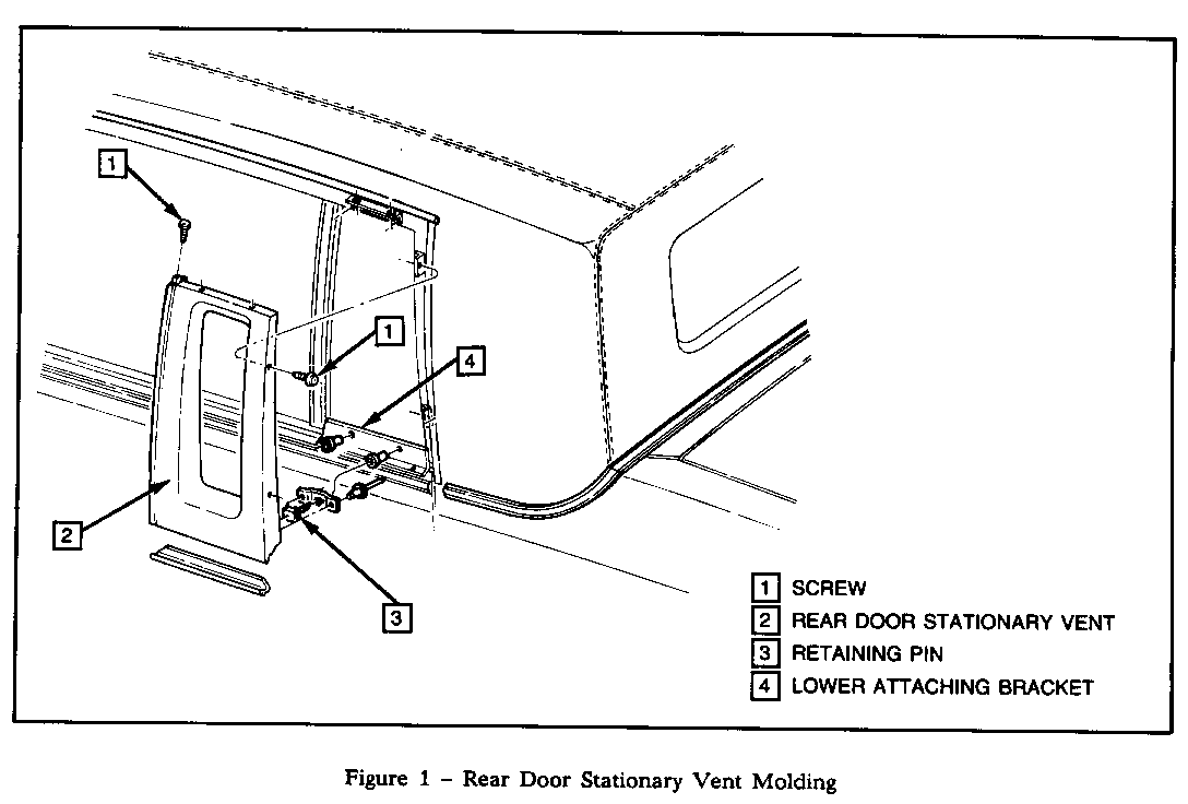
REAR DOOR STATIONARY VENT MOLDING
Remove or Disconnect (Figure 1)
1. Screws (1)
2. Rear door stationary vent molding (2) by grasping lower edge and pulling outboard to disengage retaining pins (3) from lower attaching bracket (4).
Install or Connect
1. Rear door stationary vent molding (2) by aligning retaining pins (3) to lower attaching bracket (4) and pressing molding in place.
2. Screws (1).
REAR DOOR STATIONARY VENT GARNISH MOLDING
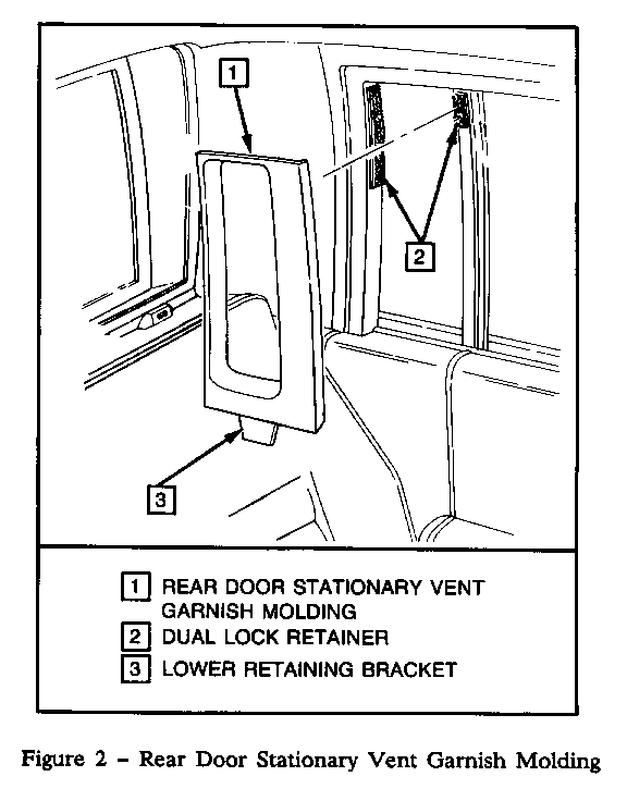
Remove or Disconnect (Figure 2)
Rear door stationary vent garnish molding (1) by pulling the upper section inboard then forward to disengage dual lock retainers (2) then lift the molding to disengage lower retainer bracket (3).
Install or Connect
Rear door stationary vent garnish molding (1) by engaging lower retainer bracket (3) then push in place to attach the dual lock retainers (2) at rear then front.
"B" PILLAR APPLIQUE ASSEMBLY
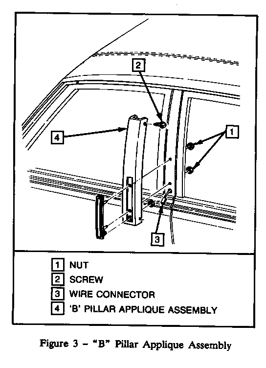
Remove or Disconnect (Figure 3)
1. Center pillar trim panel
2. Nuts (1)
3. Screws (2)
4. Wire connector (3)
5. "B" pillar applique assembly (4)
Install or Connect
1. Wire connector (3)
2. "B" pillar applique assembly (4)
3. Screws (2)
4. Nuts (1)
5. Centre pillar trim panel
REAR WINDOW GARNISH MOLDING
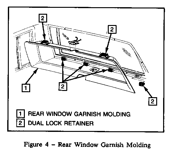
Remove or Disconnect (Figure 4)
1. Fiber optic assembly cover
2. Center high mounted stop lamp assembly
3. Rear window garnish molding (1), by pulling to detach the dual lock retainers (2)
Install or Connect
1. Rear window garnish molding (1), by pushing in place to attach the dual lock retainers (2)
2. Center high mounted stop lamp assembly
3. Fiber optic assembly cover
ROOF BONNET ASSEMBLY
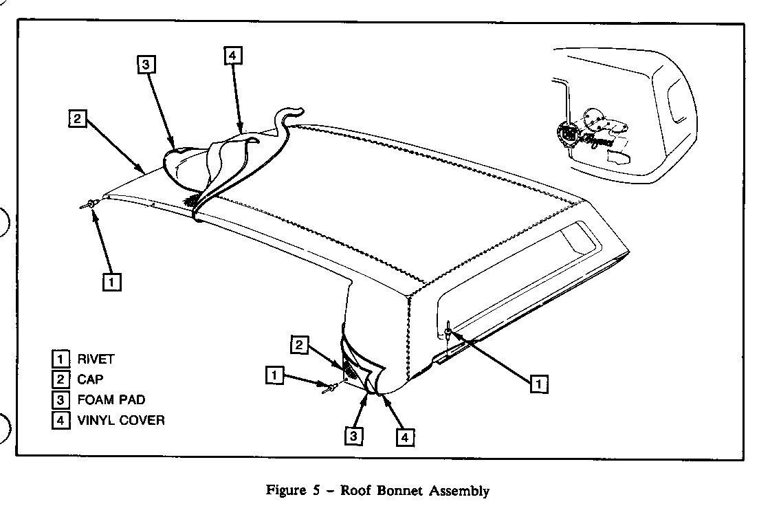
Remove or Disconnect (Figures 5 and 6)
1. The following parts must be removed prior to removing the roof bonnet assembly:
a. Roof drip moldings b. Rear quarter belt moldings c. Windshield reveal moldings d. Roof scripts and emblems
2. Tape protective cover to all adjacent painted surfaces.
3. Using a hot air gun held about 15mm (1") from the vinyl and rotated in a circular motion to avoid overheating vinyl. Remove vinyl from windshield pillars and loosen all vinyl edges along roof cap outboard edges.
4. Using a putty knife or similar flat-bladed tool work foam and pad loose from all edges of cap to expose all attaching rivets. If equipped with a sliding sunroof, the vinyl and foam pad will have to be removed from windshield pillars to the rearward edge of the sunroof opening to expose attaching rivets at roof opening.
5. Using a 3.2mm (1/8") drill with a drill stop set to 50mm (1/2") depth drill out rivets (1) securing cap.
6. Using a flat-bladed tool release bonnet assembly from roof.
7. With assistance of helper lift bonnet assembly off.
Clean
1. All remaining foam pad from roof panel.
2. Rivet holes and coat with zinc chromate.
Install or Connect
1. Apply body sealer to roof 3M bedding and glazing compound, 3M P/N 08509 or equivalent.
2. With aid of helper, position new bonnet to roof and align holes in cap to holes in roof.
Important
Rivet holes should line up. If new holes are required, seal old holes with medium-bodied sealer. Drill new holes 1/8" diameter as required using drill stop set to 50mm (1/2") depth. All rivets must be aluminum, closed end type, and must be flush with cap.
3. 1/8" x 3/8" rivets (1 Figure 5).
4. Apply 3M vinyl trim adhesive, 3M P/N 8046 or equivalent, to underside of pad and to corresponding roof panel surface, and slick pad to roof to avoid wrinkles and air bubbles.
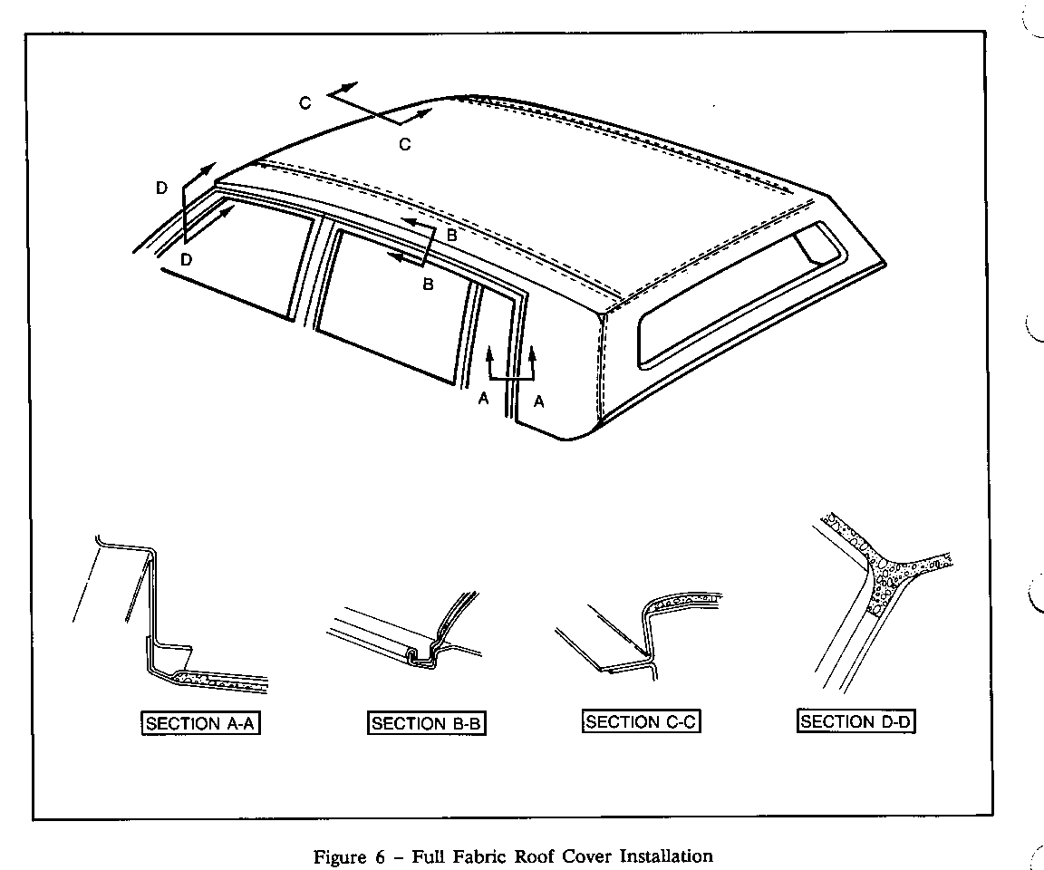
5. Trim excessive pad material as follows: (Figure 6)
a. Slightly inboard of weld-on studs on quarter in such a manner as to allow edge of moldings to nest evenly next to pad after top is installed.
b. In rear door opening flush with edge of roof, refer to Figure 6 view A-A.
c. On roof rails in line with outboard top of drip molding, refer to Figure 6 view B-B.
d. Down windshield pillar 3 below windshield upper breakline, refer to Figure 6 view D-D.
e. Flush with windshield opening at breakline.
Be certain pad is cemented along all edges that have been trimmed.
6. Using medium grade sand paper, feather trimmed edge of pad on windshield pillar flush with windshield pillar.
7. Apply 3M vinyl trim adhesive 8046 or equivalent to top surface of foam pad, roof panel, windshield pillars, and to corresponding surface of vinyl.
8. Firmly slick vinyl to valance panel starting at center working to outboard ends.
9. Firmly slick vinyl to sail panels.
10. Firmly slick vinyl to roof sides into and around drip rails.
11. Firmly slick vinyl to windshield opening wall creasing firmly into corner.
12. Firmly slick vinyl to windshield pillars.
13. Trim and cement remaining excess material as follows: (Figure 6)
a. Along belt molding studs so that vinyl falls below weld studs.
b. Along rear door opening so that vinyl wraps onto facing of rear pillar.
c. Along outside lower edge of drip rail.
d. Along windshield opening at rabbet wall and cut notches in vinyl at all weld on studs in windshield opening.
14. Remove protective covers from the body.
15. Install all previously removed moldings and roof emblems.
BACK GLASS
Back glass is inside loaded and is removed by taping and breaking.
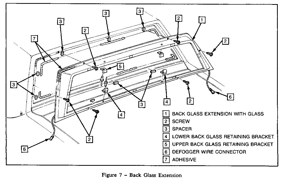
Remove or Disconnect (Figure 7)
CAUTION:
To prevent personal injury, gloves and safety glasses should be worn when breaking and removing glass.
1. Necessary interior trim as specified in Section 6B.
2. Using a 3.2mm (1/8") drill with a drill stop set to 50mm (1/2") depth drill out rivets securing back glass retaining brackets (4 and 5).
3. Place protective cover over rear seat cushion, seat back and rear seat to back window trim panel. Cover painted surface of rear compartment and rear end panel to protect painted surface.
4. Tape the inside and outside of the glass so that the glass will not fall out and also eliminate scattering of glass fragments. Hit lower corner of glass with a punch and hammer to break glass. Remove taped glass.
Clean
Glass fragments from interior and exterior of car.
5. Remainder of procedure same as extended method.
BACK GLASS EXTENSION WITH BACK GLASS
The back glass extension is secured to the body opening with urethane adhesive. The back glass extension is installed in the same manner as the extended method for windshield and back glass.
CAUTION:
To prevent personal injury, gloves and safety glasses should be worn when removing glass.
Remove or Disconnect (Figure 7)
1. Roof bonnet assembly (see Section 8D).
2. Rear window garnish molding (see Section 8D).
3. Rear window defogger wire connectors.
4. Mask off area around back glass extension to protect painted surfaces and to aid in clean up after installation.
5. Screws (2) retaining extension to body.
6. Using a razor or utility knife make a preliminary cut around entire perimeter of extension staying as close to edge of extension as possible.
7. Using cold knife J-24402-A or equivalent, cut out extension, keeping blade as close to edge of extension as possible. Remove back glass extension with back glass.
Clean
Glass opening of any loose material. If extension is to be reinstalled, all urethane must be removed from extension. Use caution not to damage the primer on the extension.
Surface of extension to which adhesive will be applied, by wiping with a clean alcohol dampened cloth. Allow to air dry.
NOTE: If the primer on the extension is damaged, re-prime using PPG two part epoxy primer DP40 and DP401.
Install or Connect
1. Spacers (3) around window opening (Figure 7) by cementing in place.
2. Prime back glass extension with black primer in urethane adhesive kit No. 9636067 or equivalent. Allow primer to dry five minutes.
3. Apply a smooth continuous bead of adhesive around edge of extension where primed in step 2. A larger diameter bead of urethane is needed.
4. Using suction cups, position back glass extension with back glass in opening. Press firmly in position to wet out and set adhesive.
5. Screws (2) to retain back glass extension in position.
6. Using small disposable brush or flat-bladed tool, paddle material around edge of extension to ensure water tight seal. If necessary, paddle additional material to fill voids in seal.
7. Water test back glass at once using soft spray. Use warm or hot water if available. Do not direct hard stream of water at fresh adhesive material. If any leaks are found paddle in extra adhesive at leak point using small disposable brush or flat-bladed tool. Water applied on top of urethane adhesive, either during water, test or as a separate operation, will speed up the cure of the urethane.
8. Rear window defogger wire connectors.
9. Rear window garnish molding (see Section 8D).
10. Roof bonnet assembly (see Section 8D).
11. Car must remain at normal room temperature for six hours to complete proper cure of adhesive.
DISCLAIMER
"We believe this source and their material to be reliable. There may be additional manufacturers of such material. General Motors does not endorse, indicate any preference for or assume any responsibility for the products or equipment from these firms or for any such items which may be available from other sources."
General Motors bulletins are intended for use by professional technicians, not a "do-it-yourselfer". They are written to inform those technicians of conditions that may occur on some vehicles, or to provide information that could assist in the proper service of a vehicle. Properly trained technicians have the equipment, tools, safety instructions and know-how to do a job properly and safely. If a condition is described, do not assume that the bulletin applies to your vehicle, or that your vehicle will have that condition. See a General Motors dealer servicing your brand of General Motors vehicle for information on whether your vehicle may benefit from the information.
