AIR CONDITIONING NOISE INSTALL INERTIA RING KIT

MODELS AFFECTED: 1986-1989 BROUGHAMS
Some 1986-1989 Broughams may experience noises associated with the A/C system. These noises may be the result of underhood components being vibrated at their resonant frequency by pumping pulsations from the A/C compressor creating an underhood noise, or a loose evaporator core vibrating against the A/C module transmitting noise through the A/C ducts. To diagnose and repair this condition use the following procedures:
To determine which repair procedure is required the noise must be recreated and identified. If the noise occurs while driving at speeds ranging from 35 to 65 mph and is perceived as originating underhood, refer to procedure A. If the noise occurs when the A/C is initially turned on and is heard through the A/C ducts then tapers off, refer to procedure B.
A. Underhood noise at 1200 to 1600 rpm or 35 to 65 mph. ------------------------------------------------------- 1. With A/C compressor engaged, engine warm, increase engine rpm to about 1200 to 1600 rpm or until the noise is recreated.
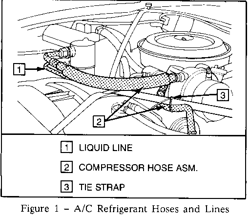
2. Inspect compressor hose assembly or liquid line for hard contact with other engine or body components. Remove tie strap from compressor discharge hose if so equipped. Refer to Figure 1. Reroute/insulate refrigerant line(s) as necessary, then retest. If noise is still present, proceed to step 3 to install inertia ring kit, P/N 2724034.
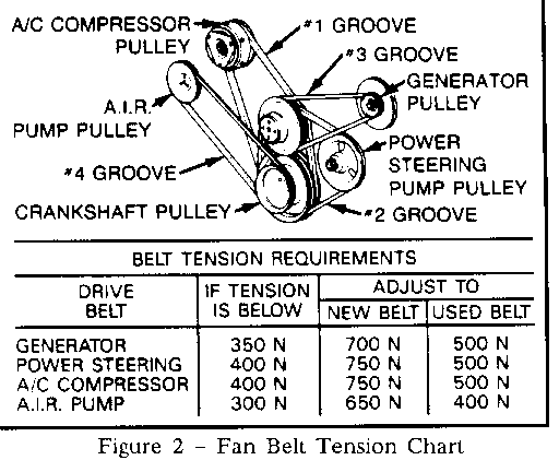
3. Inspect all fan belts, especially the compressor belt for proper tension as listed in Figure 2.
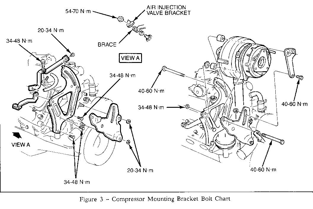
4. Inspect all compressor mounting bracket bolts for proper torque as listed below in Figure 3.
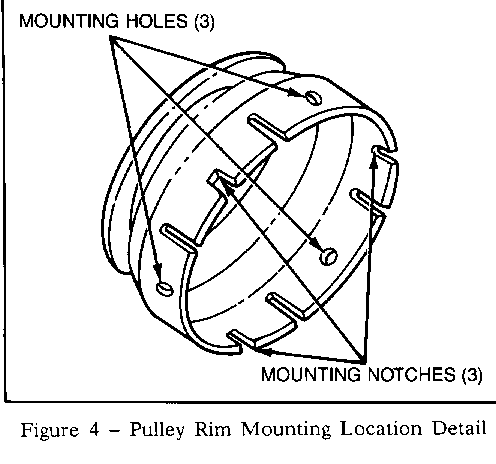
5. Remove the three mounting screws and lock washers at the pulley rim "mounting hole" locations. Refer to Figure 4. (The pulley rim "mounting holes" are located 120 degrees apart radially around the rim or every other mounting screw location.)
IMPORTANT: For identification purposes, washers locked over the edge of the pulley rim at the "mounting hole" locations will not usually dimple down in the center like the indentation of the lock over at a "mounting notch" screw location.
6. Temporarily make a trial fit of the inertial ring to the pulley rim. If any portion of the sheer edge of the pulley rim prevents the installation of the inertia ring, the raised edge may be filed off to remove the excess metal and to facilitate installation. DO NOT use undue force of cock the ring in assembling the inertia ring in place over the pulley rim that could cause ring distortion or stress.
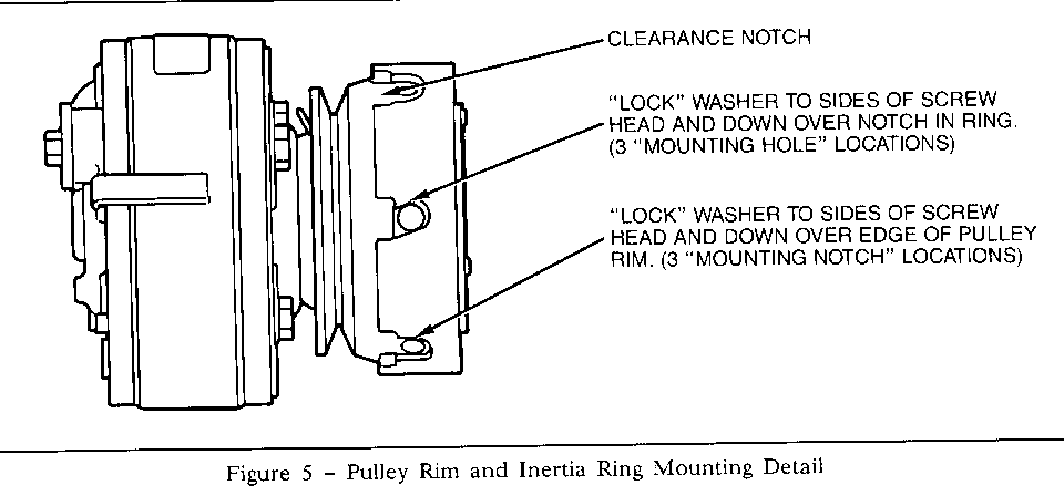
7. Assemble the inertia ring onto the pulley rim being careful to align the inertia ring mounting holes with the mounting holes in the pulley rim. If the inertia ring must be rotated on the pulley rim for centering the mounting holes and cannot be shifted by hand, use a drift punch or blunt tool and a hammer to carefully tap the inertia ring at a clearance notch to move the ring into position. Refer to Figure 5.
8. Install a special lock washer onto each 1/4-28 x 17/32" mounting screw.
9. Apply Loctite 601, or equivalent, to the screw threads of each mounting screw and threads of the mounting holes in the clutch rotor. Wet the threads thoroughly to ensure complete thread coverage.
10. Install the screws into the mounting holes and tighten finger tight. Torque each screw to 100 in. lbs. torque.
11. Lock the three screws in place by flattening the special washer against two sides of the hex head screw using vise grip pliers and one portion of the lock washer bent down over the edge of the inertia ring slot. Refer to Figure 5. DO NOT move the screw heads from the torqued position. Locking of the screws must be similar to the production forming of the lock washer in order to effectively retain the screw.
12. Retighten the compressor drive belt to proper belt tension.
13. Check compressor and system operation.
IMPORTANT: Unless the three 1/4-28 x 5/16" pulley rim mounting screws and lock washers need to be replaced for some reason, these parts are excess and may be retained for use on some future service procedure. If used, the screws should be torqued into place (100 in. lbs. torque) using Loctite 601, or equivalent, on the threads and locked into place similar to the original locking method.
For warranty purposes use Labor Operation T6382 at .3 hour.
B. Noise heard through the A/C ducts at the beginning of A/C engagement. ------------------------------------------------------------------------ 1. Disconnect negative battery cable.
2. Disconnect electrical connectors (2) power module (1) at the blower fan.
3. Remove blower fan (5 bolts, 1 ground).
4. Remove weather strip above fire wall halfway across.
5. Remove primary and secondary inlet screen and windshield washer nozzle (6 bolts).
6. Remove Power Module (2 bolts).
7. Remove compressor cycling switch from evaporator/heater case and reposition (2 bolts).
8. Remove heater A/C module cover.
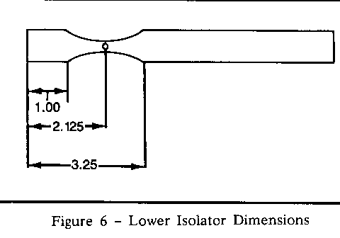
9. Cut 9 inch length of 3/4 inch diameter heater hose lengthwise in half to form a "C" shape, and make cut outs as shown in Figure 6.
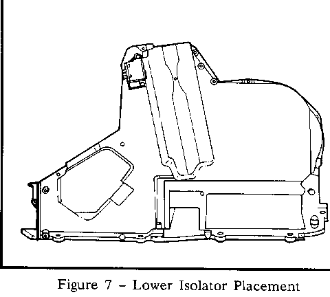
10. Place heater hose at bo tt om of the reservoir so the outside diameter is in contact with the evaporator. No adhesive is necessary. Refer to Figure 7.
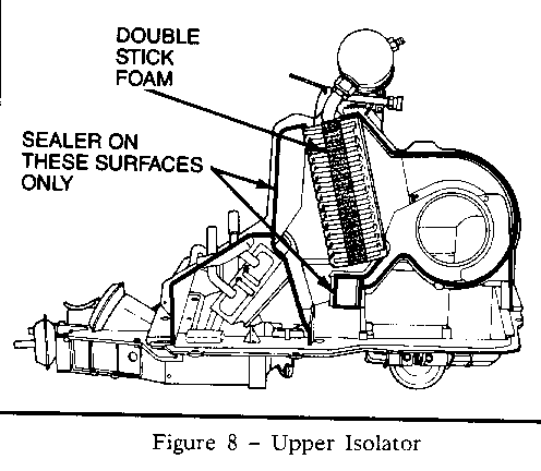
11. Cut 9 inch piece of double-stick foam tape and place on the evaporator core as shown in Figure 8.
12. Reinstall all parts.
For warranty purposes use Labor Operation T6329 at 1.0 hour.
General Motors bulletins are intended for use by professional technicians, not a "do-it-yourselfer". They are written to inform those technicians of conditions that may occur on some vehicles, or to provide information that could assist in the proper service of a vehicle. Properly trained technicians have the equipment, tools, safety instructions and know-how to do a job properly and safely. If a condition is described, do not assume that the bulletin applies to your vehicle, or that your vehicle will have that condition. See a General Motors dealer servicing your brand of General Motors vehicle for information on whether your vehicle may benefit from the information.
