FRT. DOOR GLASS REPLACEMENT INSTALLATION AND ADJUSTMENT

VEHICLES AFFECTED: 1986 'H' MODELS AND 1985-86 'C' MODELS
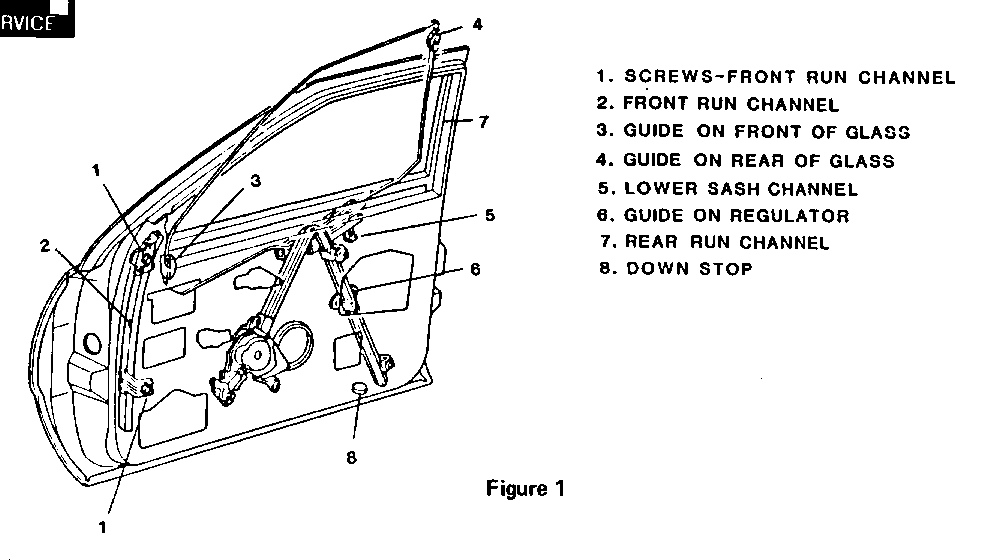
The 1986 Body Service Manual for the 'C' and 'H' styles was released without the front door glass adjustment procedure included in the door glass installation procedure. The correct method of installing and adjusting front door glass is as follows (numbers in parenthesis refer to Figure 1):
A condition may also exist on some 1986 'H' models and 1985-86 'C' models in which the front door glass becomes repetitively disengaged from the run channels. Several factors that may contribute to this condition are included in this bulletin.
INSTALL OR CONNECT: (REFER TO FIGURE 1) ------------------ 1. Front run channel (2) and screws (1) to door; tighten loosely.
2. Glass lower sash channel to guide on regulator by lowering glass into door from outboard side of door frame and rotating glass until the regulator guide is connected to the glass sash channel.
3. Rear guide (4) on glass to rear run channel (7) by pulling back on glass until rear guide snaps into rear run channel.
4. Front guide (3) on glass to front run channel by reaching through front access hole indoor inner panel. Grasp front run channel and snap onto glass guide, pushing front channel rearward until guide snaps into channel.
ADJUSTMENT PROCEDURE
A. Adjust glass by moving glass upward into door frame header, approximately 5 mm (.20") short of full up position.
B. Grasp door glass and move glass rearward to assure full engagement of glass and glass guide pin to glass run channel and retainer; then move glass fully upward into door header.
C. Tighten previously loosely installed upper and lower glass run channel retainer screws (1) to specified torque of 10 N.m. (93 lbs. in.)
D. Cycle glass down and to full up position to check operation of glass.
5. Install insulator for outside mirror.
6. Install outside mirror cover.
7. Install inner belt sealing strip and fillers.
8. Install trim panel upper retainer.
9. Install water deflector.
10. Install trim panel.
FACTORS THAT MAY CONTRIBUTE TO DOOR GLASS DISENGAGEMENT INCLUDE:
- Improper adjustment of door glass during reinstallation. - Rear guide clip not secured. - Wrong guide clip(s) installed. - Mirror "patch" insulator binding in front run channel. - Regulator does not have up stop and overtravel occurs. - Overtravel in the down position (primarily 2-door cars).
IMPROPER ADJUSTMENT OF DOOR GLASS:
Follow the published procedure outlined in this bulletin for installation and adjustment.
IMPORTANT: In or out alignment of the window frame must be checked carefully to ensure smooth operation of the glass through full. up and down travel.
REAR GUIDE CLIP NOT SECURED:
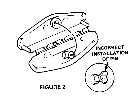
During installation of a pin guide to the glass, it is possible that both halves of the plastic split pin will not lock in the female collar. See Figure 2. If only one has seated properly, it typically goes unnoticed; however, the normal stress applied to the part can be enough to shear or damage the pin.
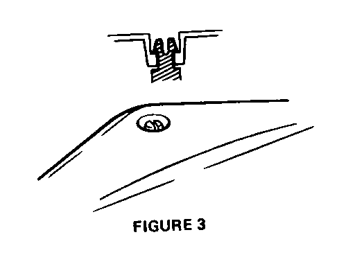
halves of the pin enter the hole and lock securely on the glass. Refer to Figure 3.
A worn clip mold condition existed on early 1986 models and may cause clip hinge binding and prevent securing of the rear clip through the glass. This condition was corrected in December. Dealer stock ordered prior to January should not be used. Parts Department current stock is good.
It is best to replace both front and rear guide clips if either one has disengaged form run channel. Remove, inspect and replace run channel if any distortion or damage (flashing on top of front channel) is evident. The run channels must not be lubricated to correct guide clip disengagement condition. Guide clips may be lubricated with a soap or silicone base lube.
WRONG GUIDE CLIPS:
Two door glass thicknesses were used. Door glass on some very early 1985 'C' models were 5 mm thick. The thickness then went to 4 mm and reverted back to 5 mm in May, 1985. Different glass thickness required different clips. Breakpoints for the latest change in 1985 to 5 mm thick glass are:
ORION PLANT F4386037 WENTZVILLE PLANT F1350147
In 1986, front door glass thickness is 5mm.
If unsure of the glass thickness, use a micrometer and measure.
5 MM = .20" 4 MM = .16"
Guide clips are colour coded; black for 4 mm and grey for 5 mm.
Correct pin guide parts information:
PART NUMBER PART NUMBER 5 MM 4 MM
FRONT 20487631 20712176 * REAR 20478732 20478733
Parts are available through the Parts Department.
MIRROR "PATCH" INSULATOR REWORK:
The mirror "patch" filler or insulator may cause a slight twist or bend in the front upper run channel due to the gasket interfering with the run channel upper retainer bracket. This interference causes a bind and does not allow the retainer to move freely when adjusting the glass. Correction of this condition will also reduce window operating efforts. The rework should be done before adjusting the door glass and consists of the following steps:
1. Remove mirror and mirror cover plate.
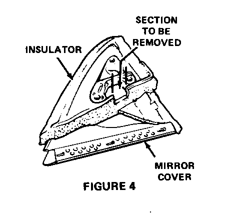
2. Remove a 20 mm (.80") side section by 13 mm (.52") deep section at the rear edge of the insulator centered between the two rear stud holes in the mirror cover plate. Refer to Figure 4. This will allow free movement of the front run channel top adjusting bolt in the slot.
3. Late production vehicles will not require any modification to the mirror "patch" filler insulator. In plant start of change VIN breakpoints are:
ORION SOP 1987 - 'C' MODEL G1334768 - 'C' MODEL G1835762 - 'H' MODEL WILLOW RUN GW405640 - 'H' MODEL
REGULATOR LACKS UP STOP:
Late production regulators have an up stop to prevent tape drive overtravel. Service stock is being updated and a future bulletin will indicate new part numbers for correction of this condition.
OVERTRAVEL IN DOWN POSITION:
Overtravel of the glass in the down position (primarily 2-door cars) is sometimes caused by the driver pushing it down by resting his arm on the top edge or from gravity and normal up/down movements of the car. In either case, this could cause the guide to bind in the front run channel and the glass to rotate at the front.
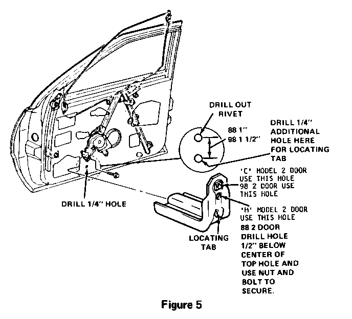
To eliminate the overtravel it is necessary to install a down travel stop in the front portion of the door. Refer to Figure 5.
DOWN TRAVEL STOP INSTALLATION 2-DOOR MODELS ONLY:
'C' MODELS
Drill out lower front regulator rivet and install down travel stop, part number 20100750, at the lower front regulator rivet hole with regulator assembly clamped between inner door panel and travel stop. It will be necessary to drill a 1/4" hole in the inner panel 1 1/2" below the rivet hole to accommodate the tab on the down stop.
'H' MODELS
Drill a 1/4" hole 1/2" down from the present hole in the travel stop as illustrated in Figure 5. Drill out lower front regulator rivet and install down travel stop, part number 20100750, at the lower front regulator rivet hole. Use a nut and bolt to fasten the regulator assembly between inner door panel and travel stop. It will be necessary to drill a 1/4" hole in the inner panel 1" below the rivet hole to accommodate the tab on the travel stop.
NOTE: A 3/8" to 1/2" long bolt is recommended for proper clearance.
The down travel stop installation will not work on vehicles equipped with the bose radio option. A rubber pad may be added to the speaker housing on these cars.
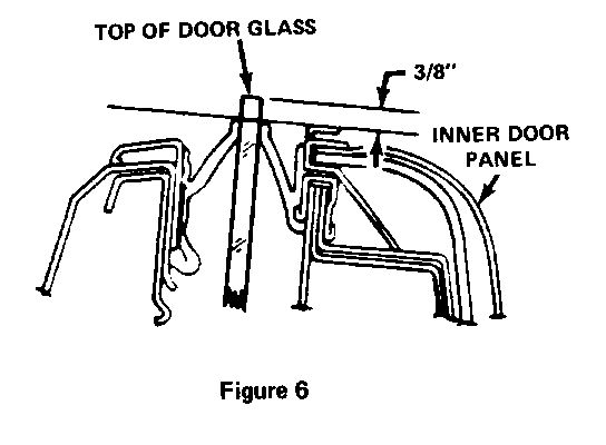
IMPORTANT: The down travel stop is designed to prevent overtravel of the door glass. It may be necessary to bend stop downward permitting door glass to stop flush to 3/8" above top of door panel. Refer to Figure 6.
NOTE: It is important that all steps in this bulletin are completed.
General Motors bulletins are intended for use by professional technicians, not a "do-it-yourselfer". They are written to inform those technicians of conditions that may occur on some vehicles, or to provide information that could assist in the proper service of a vehicle. Properly trained technicians have the equipment, tools, safety instructions and know-how to do a job properly and safely. If a condition is described, do not assume that the bulletin applies to your vehicle, or that your vehicle will have that condition. See a General Motors dealer servicing your brand of General Motors vehicle for information on whether your vehicle may benefit from the information.
