Special Tools
EN 46111 Crankshaft Rotation Socket
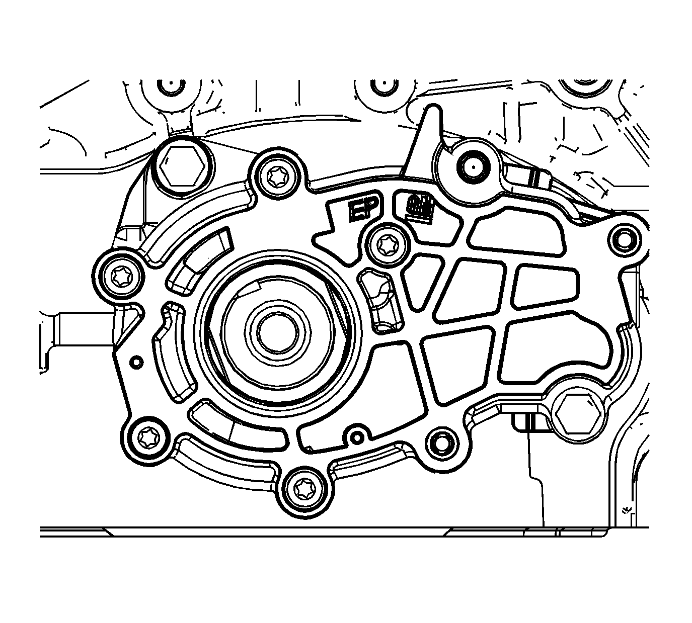
- Ensure that the crankshaft is in the stage one timing drive assembly position using the
EN 46111 . Refer to
Camshaft Timing Drive Chain Alignment Diagram.
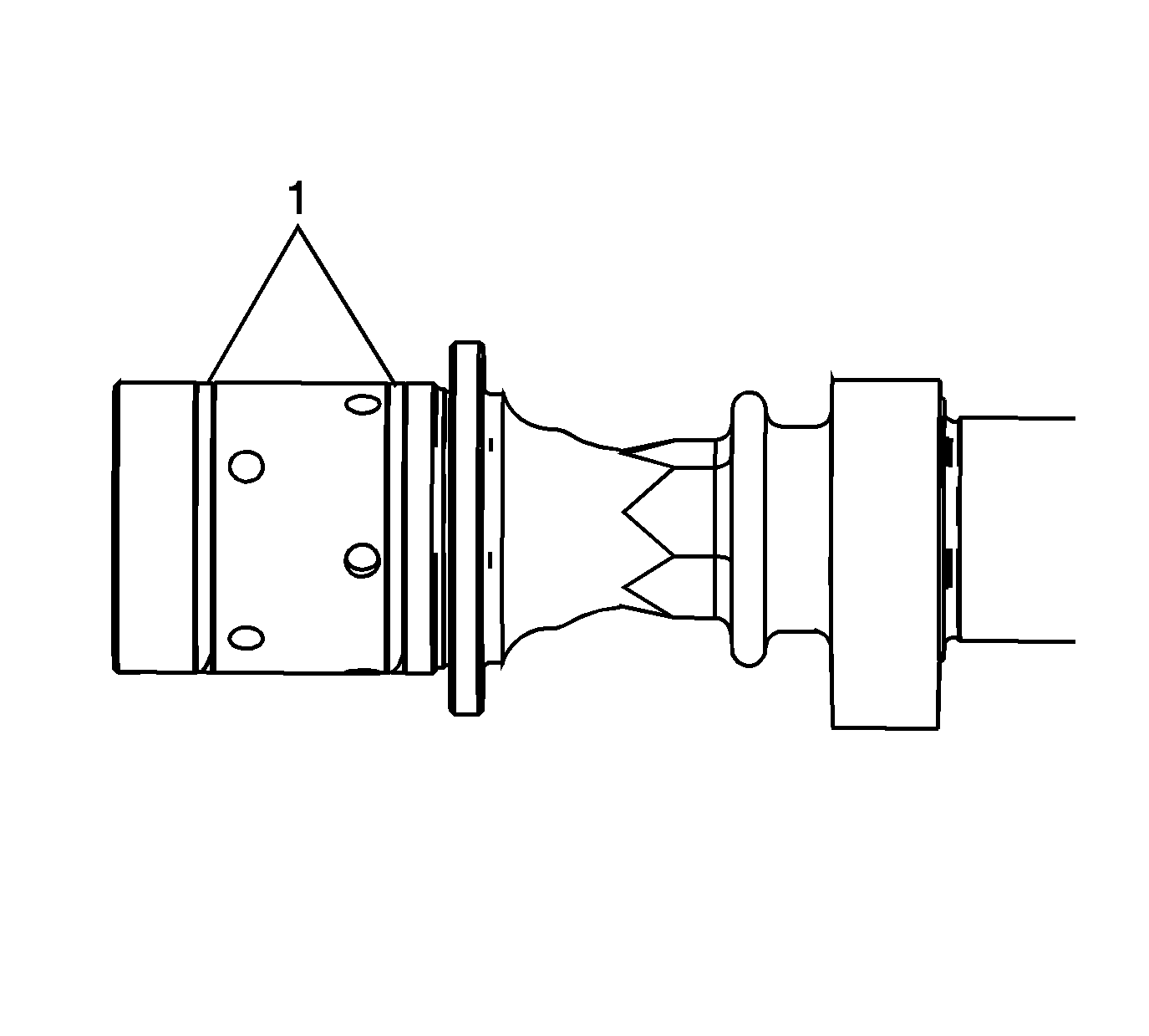
- Ensure that the camshaft sealing rings (1) are in place in the camshaft grooves.
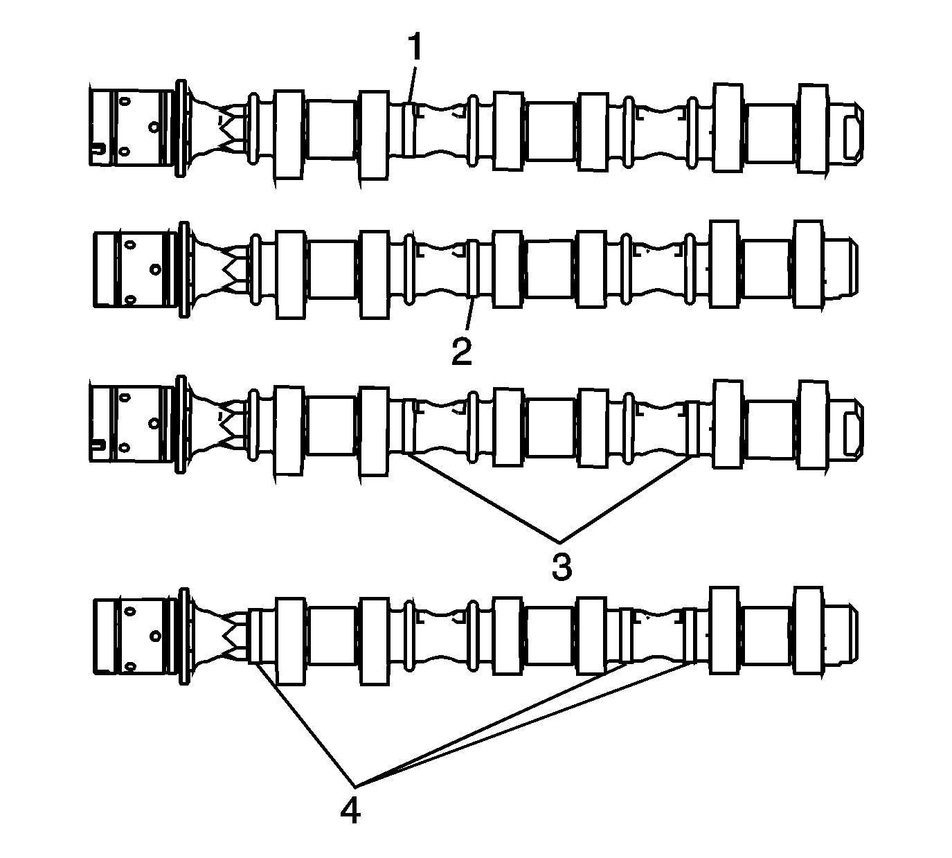
- Select the proper camshaft for the particular installation location. The ring placement is defined as follows:
| 3.1. | The number 2 identification ring for the right exhaust camshaft is machined off (1). |
| 3.2. | The number 3 identification ring for the right intake camshaft is machined off (2). |
| 3.3. | The number 2 and 5 identification rings for the right intake camshaft is machined off (3) - Fourth Design, Camshaft Timing Drive System. |
| 3.4. | The number 1, 4 and 5 identification rings for the right exhaust camshaft is machined off (4) - Fourth Design High Output, Camshaft Timing Drive System. |
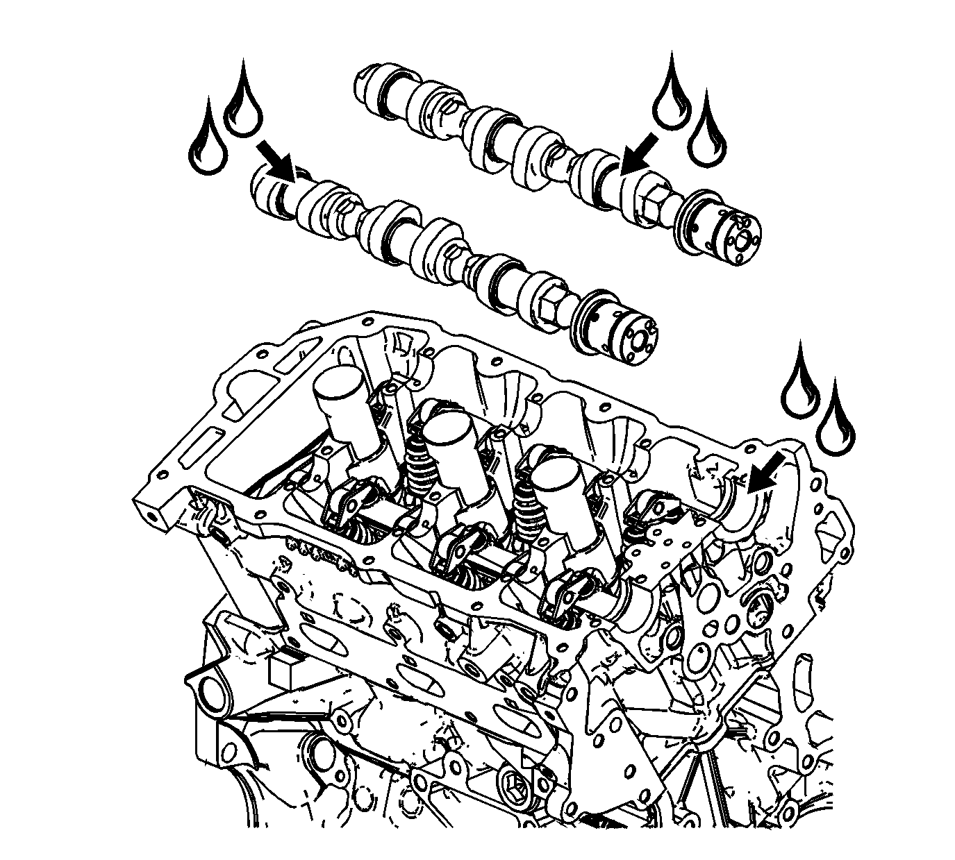
- Apply a liberal amount of lubricant GM P/N 12345501 (Canadian P/N 992704) or equivalent to the camshaft journals and the right cylinder head camshaft carriers.
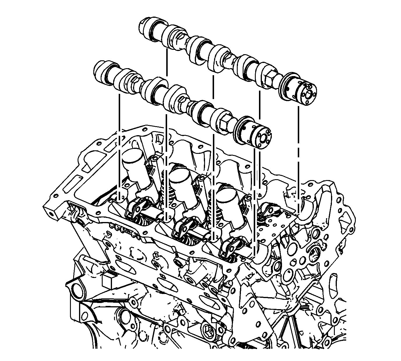
- Place the right intake and right exhaust camshafts in position in the right cylinder head.
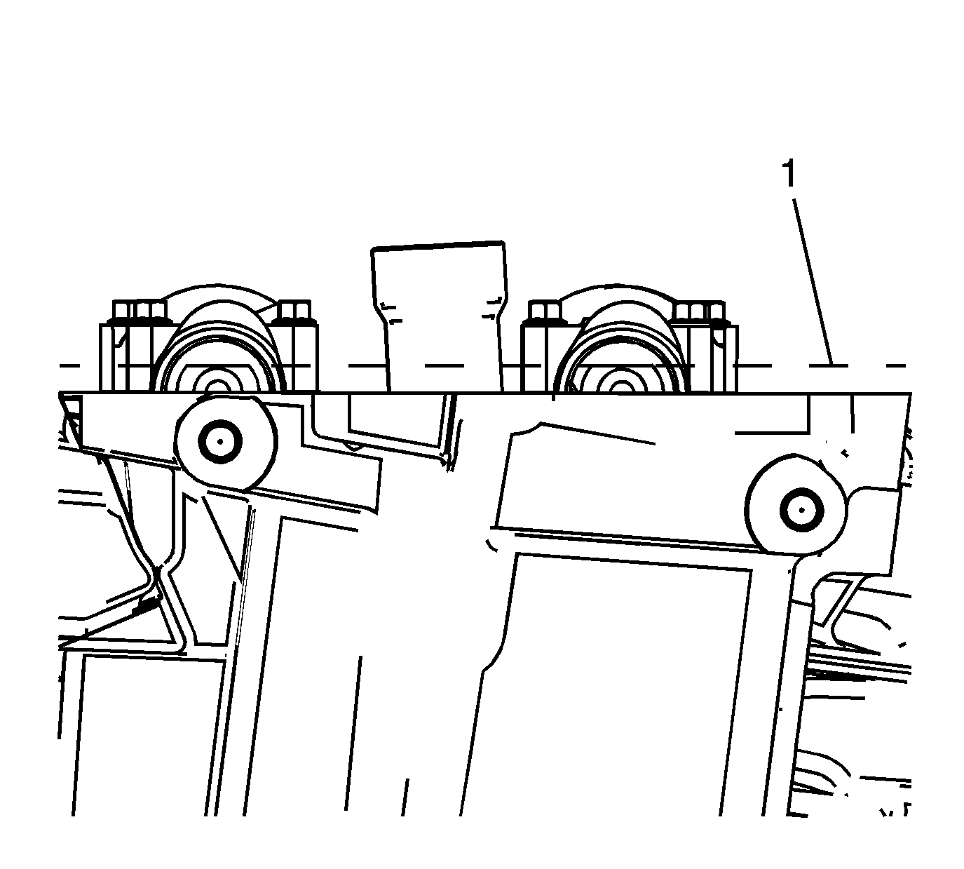
- Position the camshaft lobes in a neutral position with the flats on the back of the camshafts up and parallel (1) with the right cylinder head camshaft cover rail.
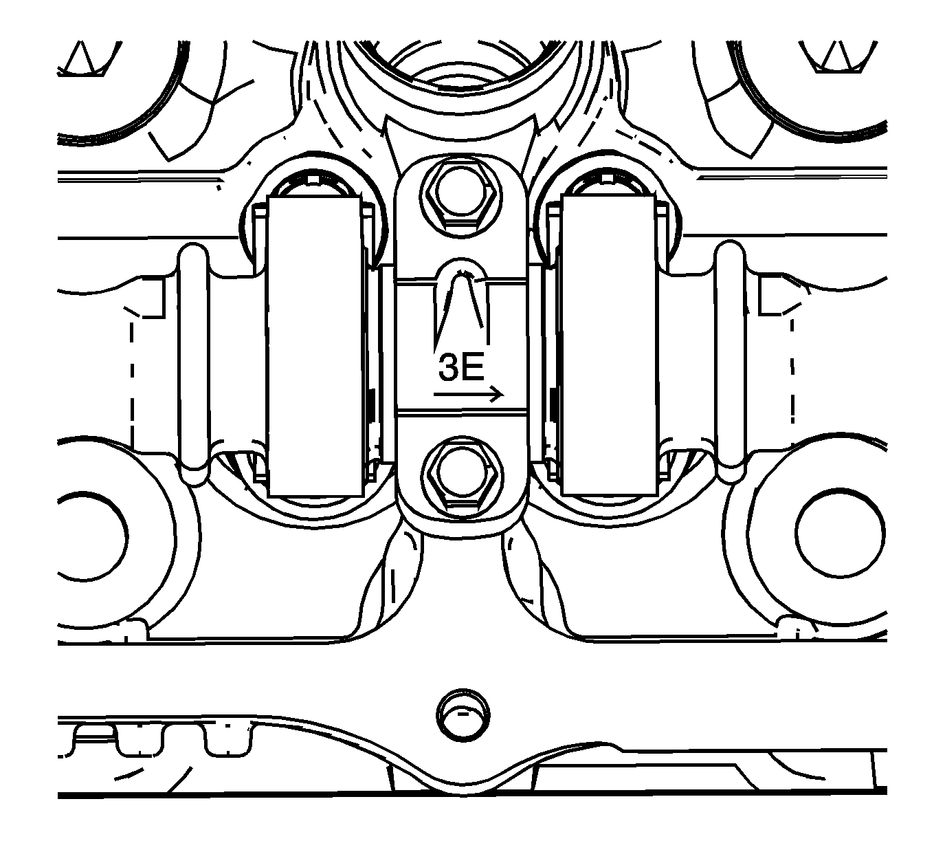
- Observe the markings on the right cylinder head camshaft bearing caps. Each bearing cap is marked in order to identify its location. The markings have the following meanings:
| • | The raised feature must always be oriented toward the center of the cylinder head. |
| • | The I indicates the intake camshaft. |
| • | The E indicates the exhaust camshaft. |
| • | The number 1, 3, 5 indicates the cylinder position from the front of the engine. |
- Apply a liberal amount of lubricant GM P/N 12345501 (Canadian P/N 992704) or equivalent to the camshaft bearing caps.
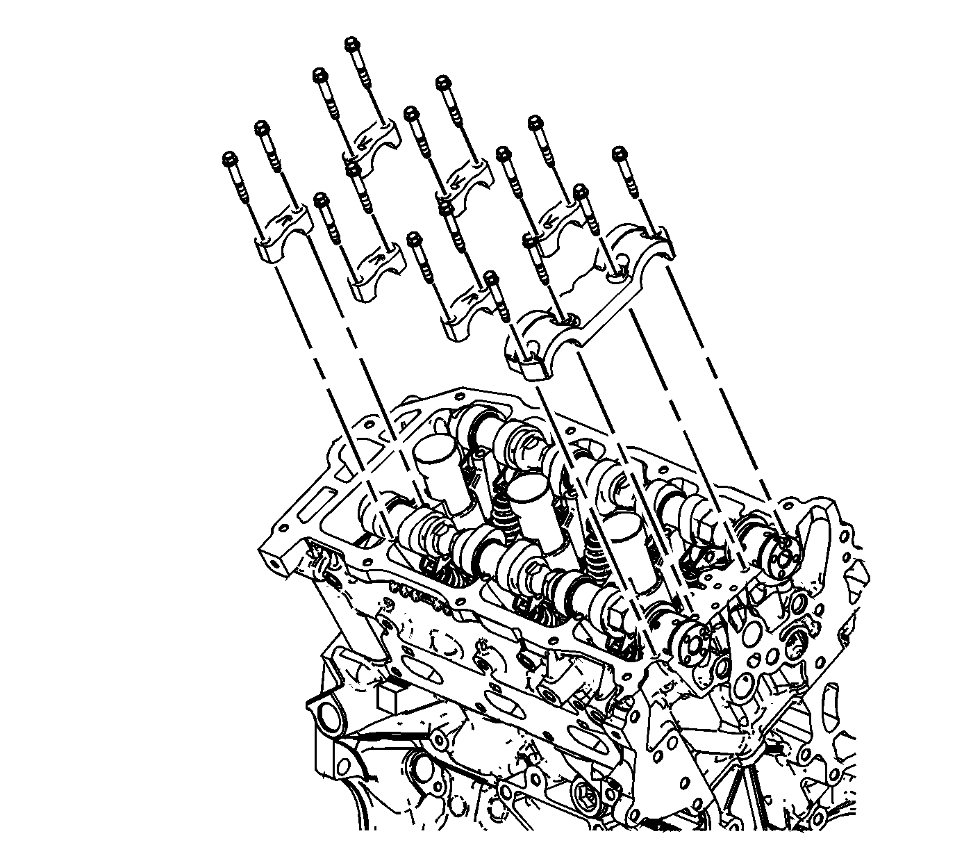
- Install the camshaft bearing thrust caps in the first journal of the right cylinder head.
- Install the remaining bearing caps with their orientation mark toward the center of the cylinder head.
- Hand start all the camshaft bearing cap bolts.
Notice: Refer to Fastener Notice in the Preface section.
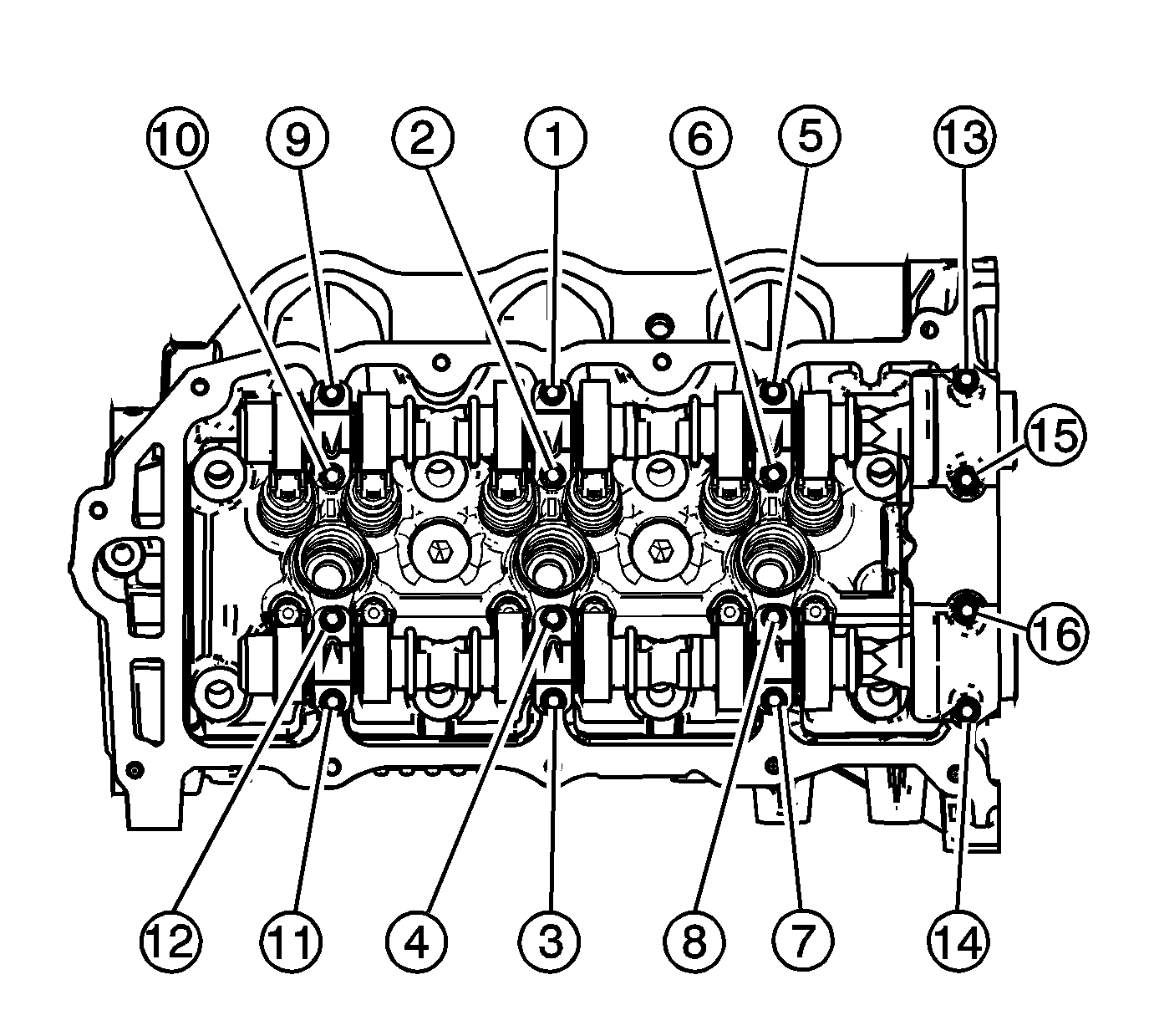
- Tighten the camshaft bearing cap bolts in the sequence shown.
Tighten
Tighten the camshaft bearing cap bolts in sequence to 10 N·m (89 lb in).
- Loosen the center intake camshaft bearing cap bolts (1, 2) and the center exhaust camshaft bearing cap bolts (3, 4).
- Retighten the center camshaft bearing cap bolts (1, 2, 3, 4).
Tighten
Retighten the camshaft bearing cap bolts to 10 N·m (89 lb in).


