For 1990-2009 cars only
Special Tools
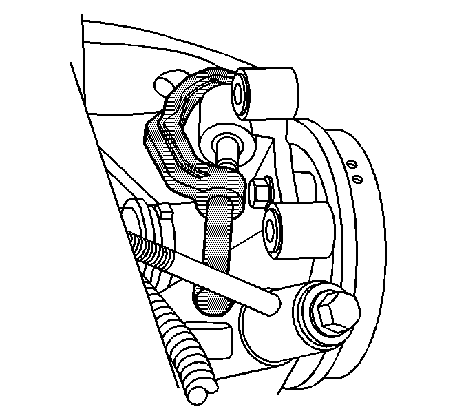
J 43631 Ball Joint Remover
Removal Procedure
- Raise and support the vehicle. Refer to Lifting and Jacking the Vehicle .
- Remove the tire and wheel. Refer to Tire and Wheel Removal and Installation .
- Remove the automatic level control link from the upper control arm.
- Remove the ABS wire harness clamp from the upper control arm.
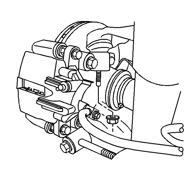
- Remove the upper control arm to knuckle retaining nut.
- Using the J 43631 , disconnect the upper control arm from the knuckle.
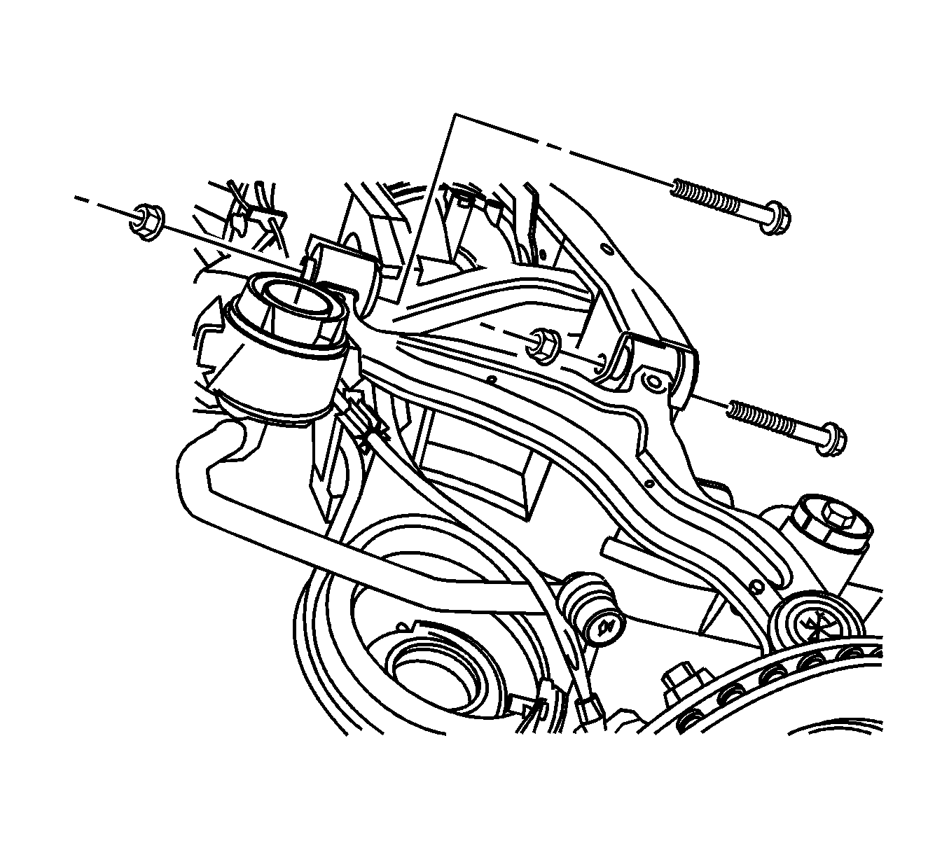
- Remove and discard the upper control arm to frame mounting bolts and nuts.
- Remove the upper control arm from the vehicle.


Notice: Do not free the ball stud by using a pickle fork or a wedge-type tool. Damage to the seal or bushing may result.

Installation Procedure
- Install the upper control arm to the vehicle.
- Install the upper control arm to frame mounting bolts and nuts.
- Install the upper control arm to the knuckle.
- Install the upper control arm to knuckle retaining nut.
- Install the automatic level control link on the upper control arm.
- Install the ABS wiring harness on the upper control arm.
- Install the tire and wheel. Refer to Tire and Wheel Removal and Installation .
- Lower the vehicle.

Important: Loosely install all fasteners before tightening.
Notice: Refer to Fastener Notice in the Preface section.
Tighten
| • | Tighten the upper control arm to knuckle nut to 66 N·m (48 lb ft). |
| • | Tighten the new upper control arm to frame mounting bolts and retaining nuts - Front to 132 N·m (9 lb ft). |
| • | Tighten the new upper control arm to frame mounting bolts and retaining nuts to 119 N·m (87 lb ft). |
