For 1990-2009 cars only
Removal Procedure
Caution: Refer to Approved Equipment for Collision Repair Caution in the Preface section.
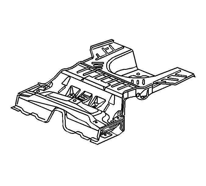
Important: Perform a full replacement only when a full frame rail assembly is installed. Use an overlap procedure for rail sectioning. The rear floor pan service part comes pre-cut to the correct length for replacement, and does not need to be modified.
- Disable the SIR system. Refer to SIR Disabling and Enabling .
- Disconnect the negative battery cable. Refer to Battery Negative Cable Disconnection and Connection .
- Remove all related panels and components.
- Remove the sealers and anti-corrosion materials from the repair area if necessary. Refer to Anti-Corrosion Treatment and Repair .
- Restorer as much of the damage as possible.
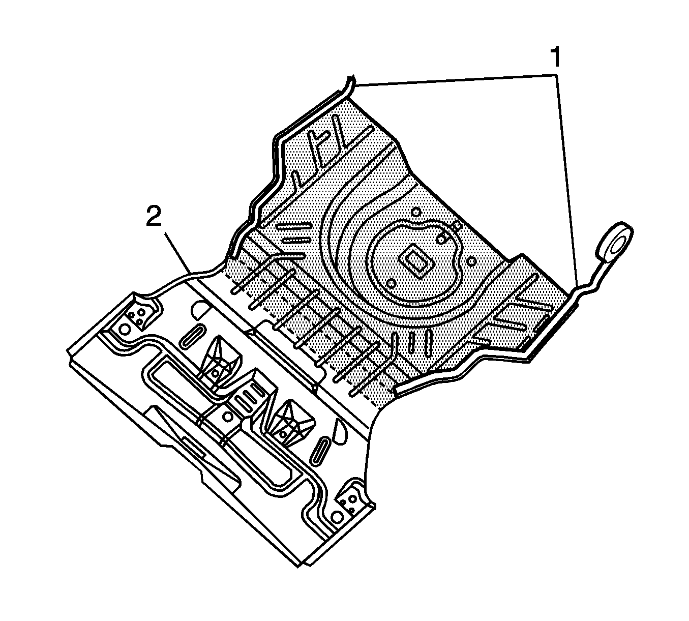
- Apply a 25 mm (1 in) wide piece of masking tape (1) to the rear compartment panel along the contour of the wheelhouse, from the number 5 crossbar to the rear of the compartment panel. Apply the tape on both sides of the rear compartment panel.
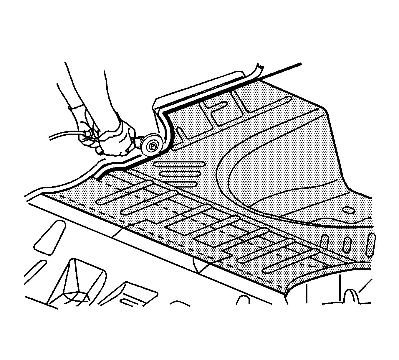
- Cut along the inboard side of the tape to create a weld flange.
- Cut the rear compartment panel at the rear edge of the number 5 crossbar.
- Locate, mark, and drill out all factory welds. Note the number and location of welds for installation of the service assembly.
- Remove the damaged rear compartment panel from the vehicle.
Important: DO not damage any inner panels or reinforcements.
Installation Procedure
- Prepare the mating surfaces as necessary.
- Apply a 25 mm (1 in) piece of masking tape along the contour of the wheelhouse from the front edge to the rear edge of the rear compartment floor service part on both sides. Cut along the outside of the tape and remove the up-turned flange.
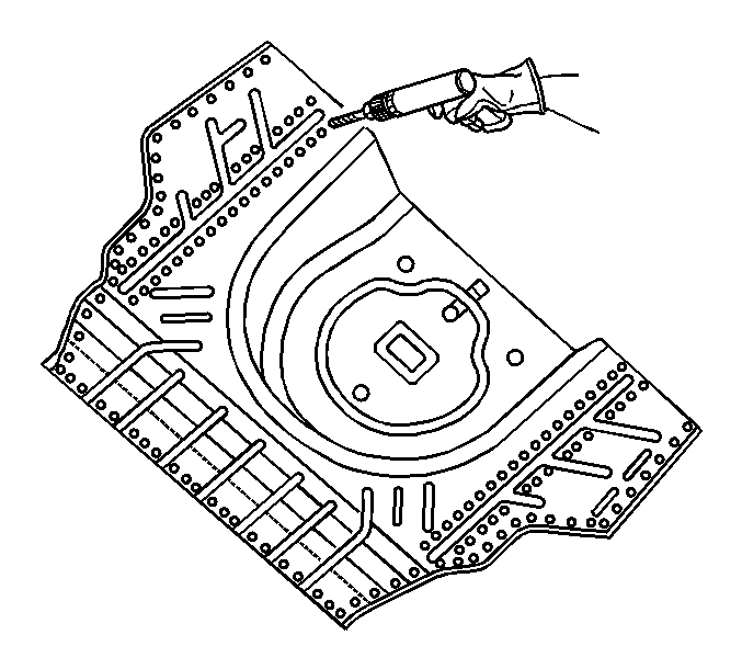
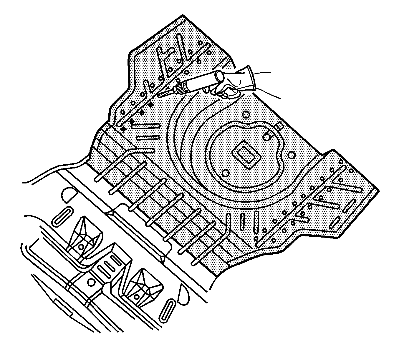
- Drill 8 mm (5/16 in) plug weld holes along the front edge of the service part spaced 40 mm (1 1/2 in) apart.
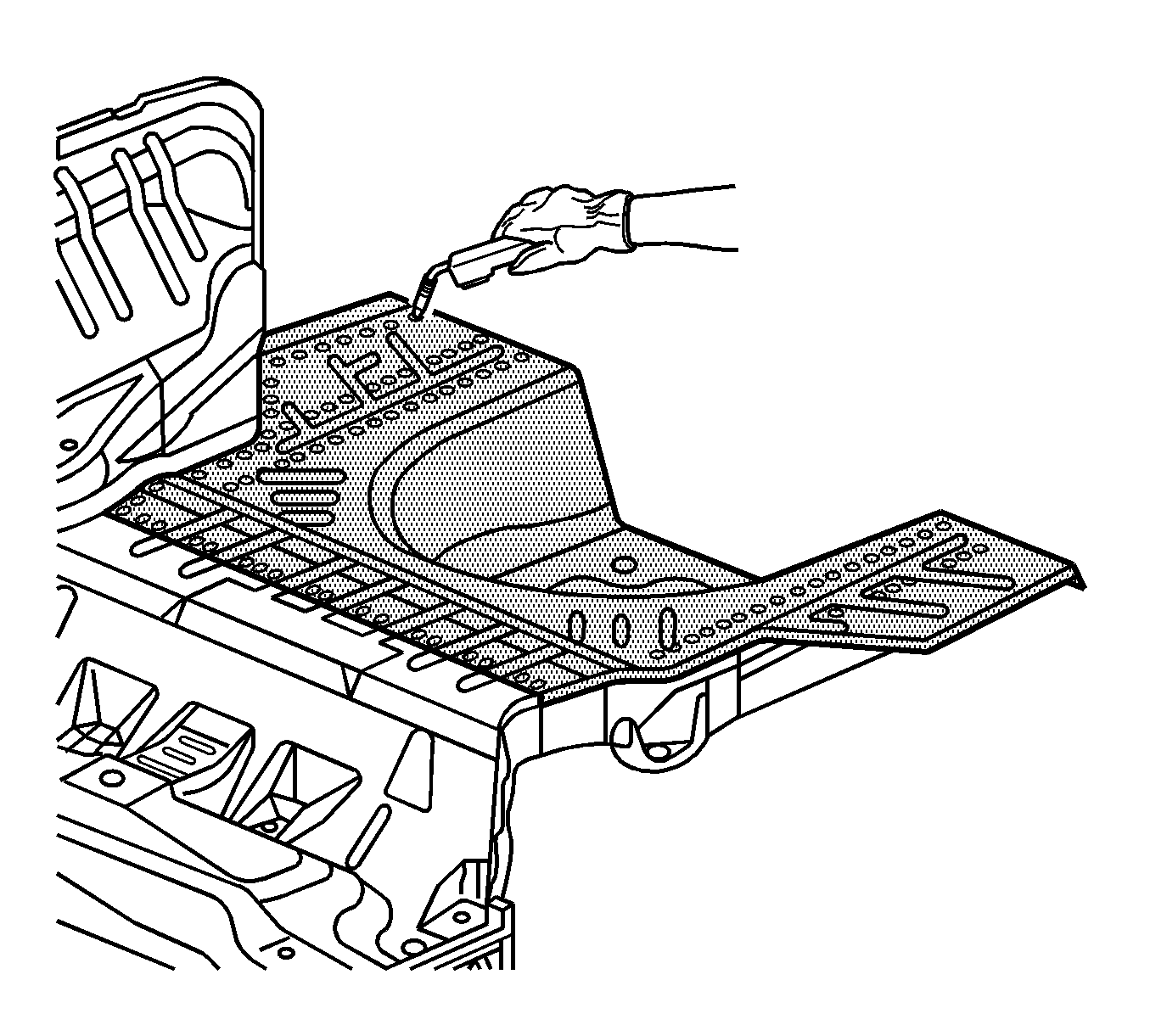
- Drill 8 mm (5/16 in) plug weld holes on the service part as necessary in the locations noted from the original panels.
- Apply 3M Weld-Thru Coating P/N 05913 or equivalent to all mating surfaces.
- Install and align the service part using 3-dimensional measuring equipment.
- Plug weld accordingly.
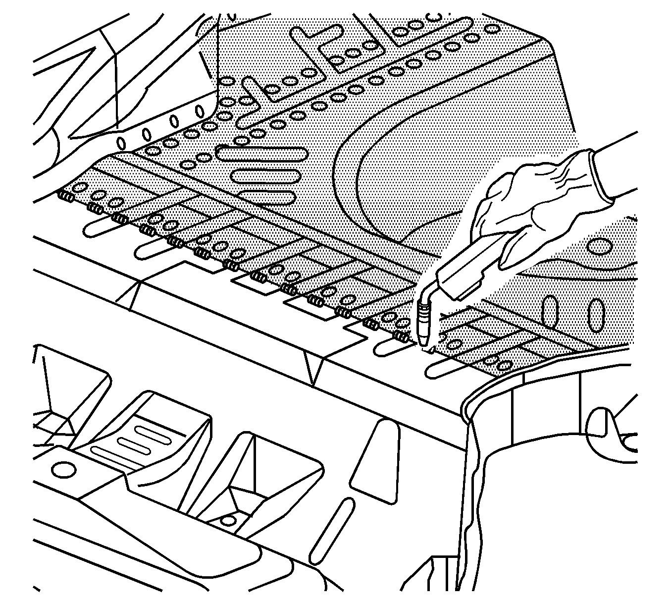
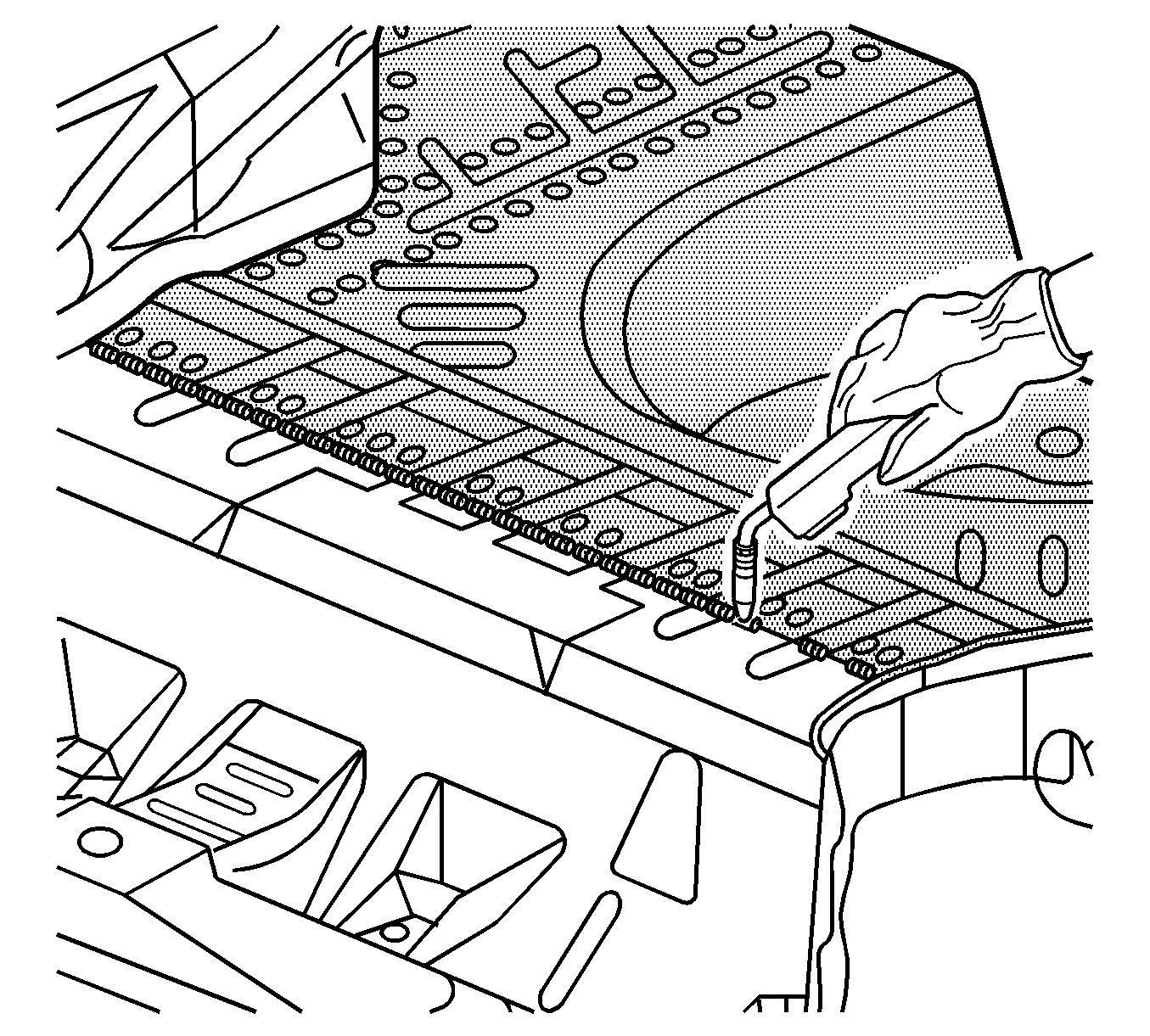
- To create a solid weld along the front of the service part with minimum heat distortion, make a 25 mm (1 in) stitch weld along the seam with 25 mm (1 in) gaps between them.
- Clean and prepare all welded surfaces.
- Paint the repaired area. Refer to Basecoat/Clearcoat Paint Systems .
- Apply the sealers and anti-corrosion materials to the repair area if necessary. Refer to Anti-Corrosion Treatment and Repair .
- Install all related panels and components.
- Connect the negative battery cable. Refer to Battery Negative Cable Disconnection and Connection .
- Enable the SIR system. Refer to SIR Disabling and Enabling .
Important: This part has structural weld-thru adhesive in the joint areas. Replace this with additional spot welds at the attachment points. This can be accomplished by adding an additional weld between each factory weld in all areas.
