For 1990-2009 cars only
Special Tools
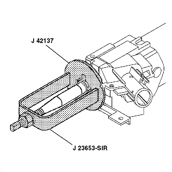
| • | J 23653-SIR Lock Plate Compressor |
| • | J 42137 Cam Orientation Plate Adapter |
Removal Procedure
- Disable the SIR system. Refer to SIR Disabling and Enabling Zone 3 .
- Remove the SIR coil. Refer to Inflatable Restraint Steering Wheel Module Coil Replacement.
- Remove and discard the bearing retainer using J 23653-SIR and J 42137 .
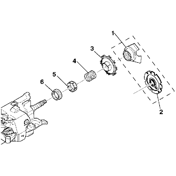
- Remove the shaft lock (2) or the cam orientation plate (1).
- Remove the turn signal cancel cam assembly (3).
- Remove the upper bearing spring (4).
- Remove the upper bearing inner race seat (5).
- Remove the inner race (6).
Caution: Refer to SIR Caution in the Preface section.


Important: Do not wipe the lubricant off the turn signal cancel cam assembly.
Installation Procedure
- Install the inner race (6).
- Install the upper bearing inner race seat (5).
- Install the upper bearing spring (4).
- Install the turn signal cancel cam (3).
- Install the shaft lock (2) or the cam orientation plate (1).
- Install the new bearing retainer using J 23653-SIR and J 42137 .
- Install the SIR coil. Refer to Inflatable Restraint Steering Wheel Module Coil Replacement.
- Enable the SIR system. Refer to SIR Disabling and Enabling Zone 3 .

Important: The electrical contact of the turn signal and multifunction switch assembly must rest on the turn signal cancel cam assembly.

