For 1990-2009 cars only
Removal Procedure
- Disable the SIR system. Refer to SIR Disabling and Enabling Zone 3 in SIR .
- Disconnect the battery negative cable. Refer to Battery Negative Cable Disconnection and Connection.
- Remove the steering wheel. Refer to Steering Wheel Replacement.
- Remove the knee bolster. Refer to Knee Bolster Replacement .
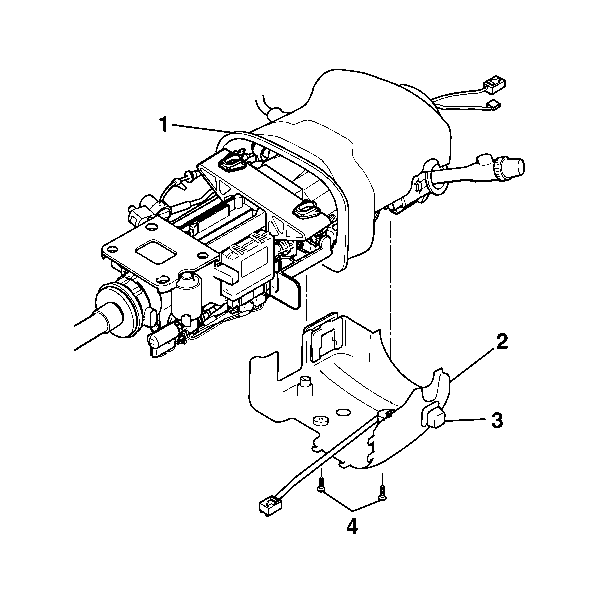
- Remove the retaining screws (4) from the lower steering column trim cover.
- Disconnect the closeout shroud from the lower trim cover.
- Disconnect the electrical connector for the power tilt and telescopic switch.
- Remove the electrical connector for the telescopic switch from the lower trim cover.
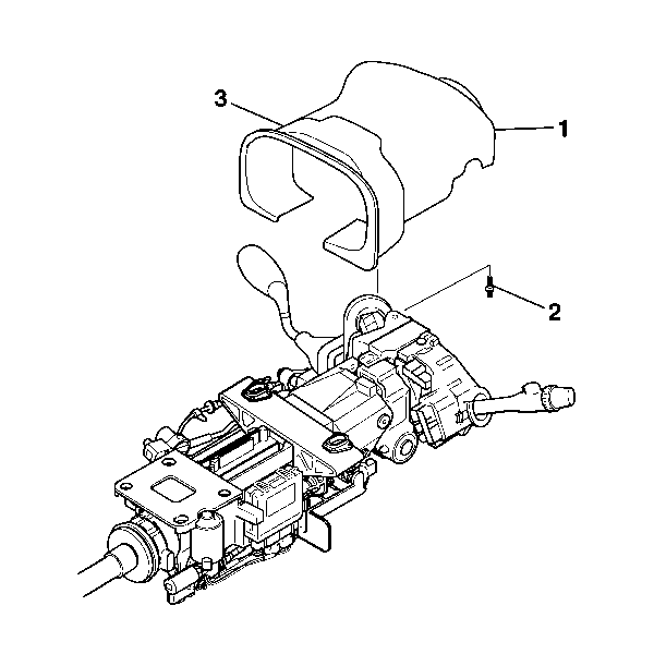
- Remove the retaining screw (2) from the upper steering column trim cover (1).
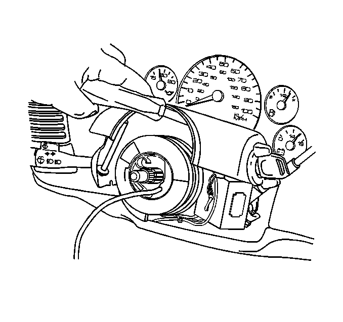
- Lift the upper trim cover to gain access to the lock cylinder access hole.
- Using a bent tip awl, insert the tip into the access hole.
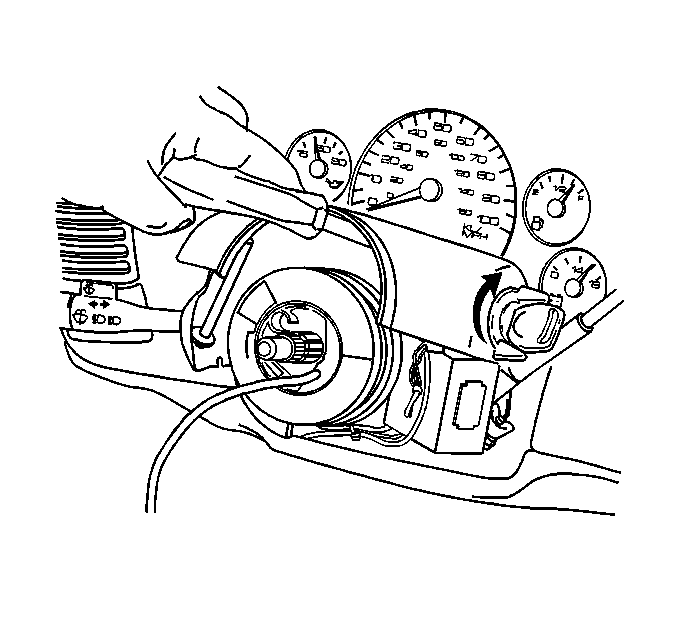
- Turn the ignition lock cylinder to the START position.
- Using the bent tip awl push down on the ignition lock cylinder retaining pin.
- Release the ignition lock cylinder to the RUN position and remove the lock cylinder.
- Remove the upper trim cover.
- Remove the closeout shroud from the upper trim cover.
Caution: Refer to SIR Caution in the Preface section.
Caution: Refer to Battery Disconnect Caution in the Preface section.


Installation Procedure
- Install the upper steering column trim cover (1) to the closeout shroud (3).
- Install the upper trim cover (1) to the steering column.
- Install the retaining screw to the upper trim cover.
- Install the Ignition lock cylinder.
- Install the lower steering column trim cover and ensure that the tabs (2) on the lower trim engage with the tabs on the upper trim cover. Snap the covers together.
- Connect the lower trim cover to the closeout shroud.
- Install the retaining screws to the lower trim cover.
- Install the knee bolsters. Refer to Knee Bolster Replacement .
- Install the steering wheel. Refer to Steering Wheel Replacement.
- Connect the battery negative cable. Refer to Battery Negative Cable Disconnection and Connection.
- Enable the SIR. Refer to SIR Disabling and Enabling Zone 3 .

Notice: Refer to Fastener Notice in the Preface section.
Tighten
Tighten the screw to 1.5 N·m (13 lb in).

Tighten
Tighten the screws to 3 N·m (27 lb in).
Notice: Avoid damaging the steering column electronic lock harness by gently removing the plugs installed in the I/P beam. Do NOT twist, pull, bend, cut, or incorrectly route the harness. Damage to the harness will require replacement of the entire electronic lock.
