Special Tools
| • | J 42385-700 High Feature Thread Repair Kit |
| • | J 42385-2000 Thread Insert Kit |
| • | J 43965 Thread Repair Extension Kit |
The thread repair process involves a solid, thin walled, self-locking, carbon steel, bushing type insert. During the insert installation process, the installation driver tool cold-rolls the bottom internal threads and expands the bottom external threads of the insert into the base material. This action mechanically locks the insert into place.
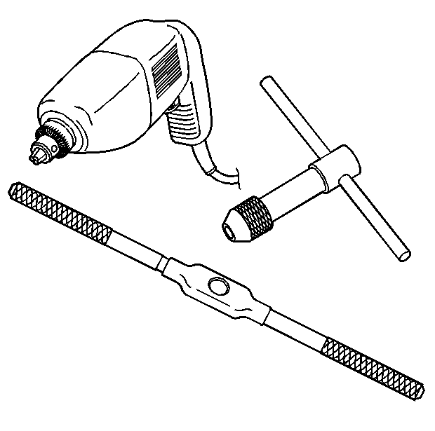
The drill bit and counter bore tool from the tool kit J 42385-700 and J 42385-2000 is designed for use with either a suitable tap wrench or drill motor. Limited access and larger hole repair may process better using a tap wrench. An extension from kit J 43965 may also be necessary to drive the thread repair tooling dependent on access to the hole being repaired. Use only a tap wrench when tapping the hole and during installation of the insert.
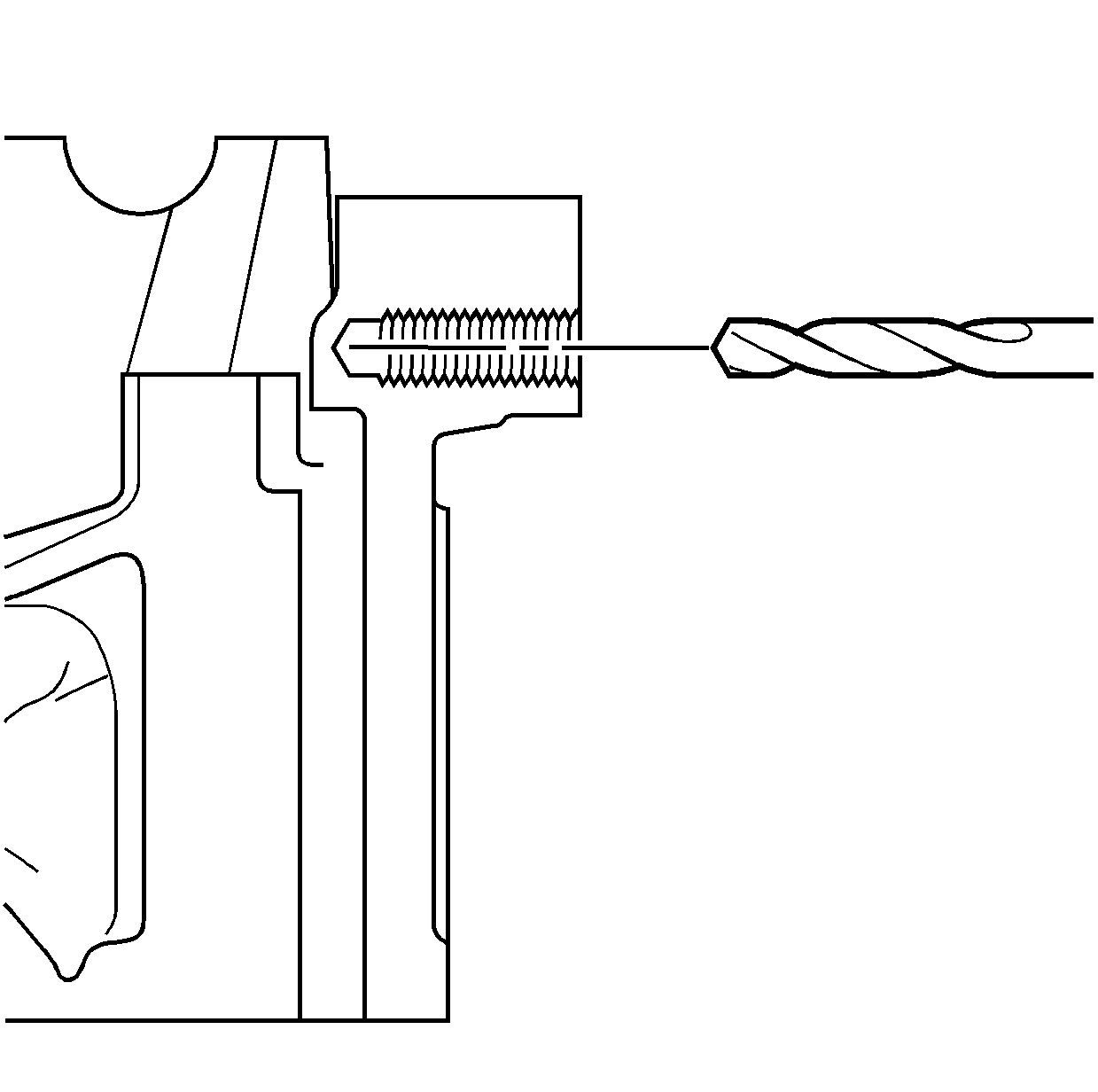
It is critical that the drilling, counterboring and tapping of the hole to be repaired follows the same centerline as the original hole.
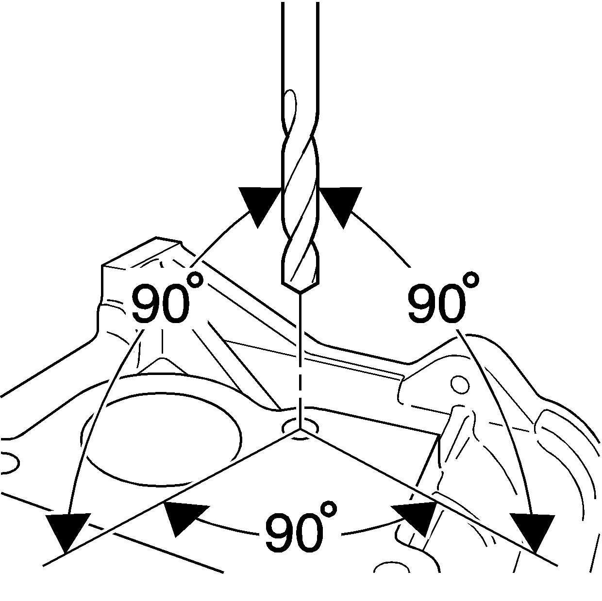
During the drilling and tapping of the hole being repaired ensure the tooling is consistently machining perpendicular to the surface of the base material.
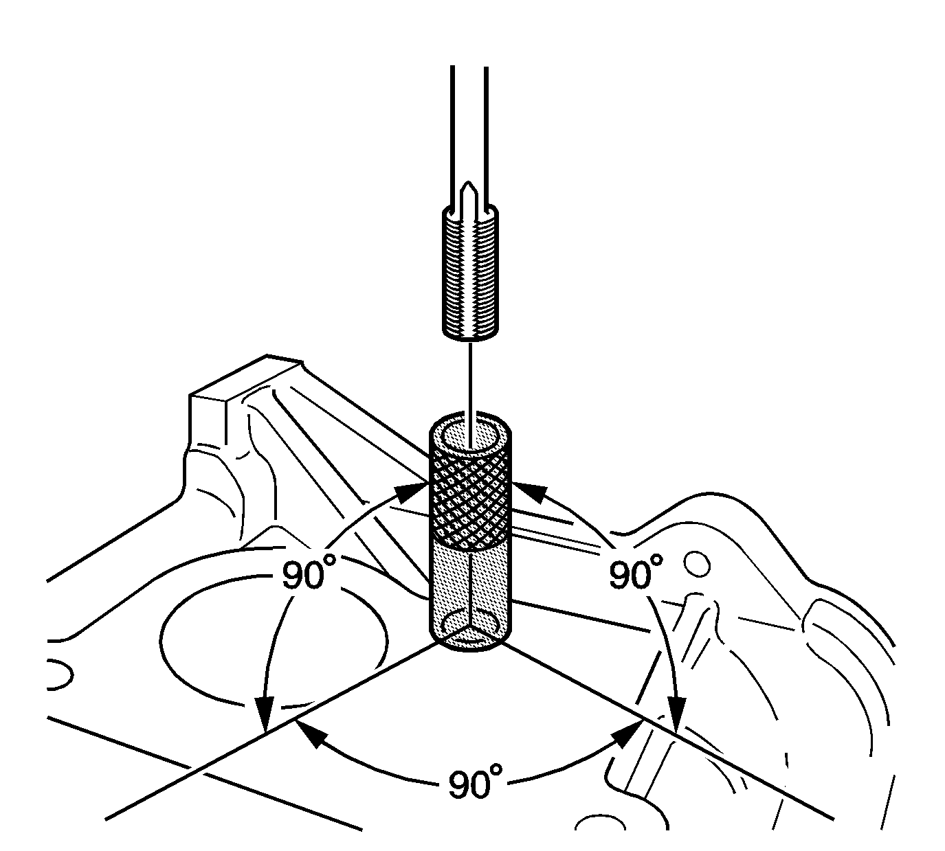
If the threaded hole being repaired has a base surface perpendicular to the hole centerline, tapping guides are available to aid in tapping the hole.
Tap Size | Tap Guide | Tap Size | Tap Guide | Tap Size | Tap Guide |
|---|---|---|---|---|---|
-- | J 42385- | -- | J 42385- | -- | J 42385- |
6 x 1.0 | 729 | 10 x 1.5 | 731 | 14 x 1.5 | 736 |
8 x 1.25 | 730 | 12 x 1.5 | 732 | 20 x 1.5 | 737 |
Standard Thread Repair - Flush Hole
Caution: Refer to Safety Glasses Caution in the Preface section.
Important: The use of a cutting type fluid GM P/N 1052864, (Canadian P/N 992881), WD 40® or equivalent is recommended when performing the drilling, counterboring and tapping procedures.
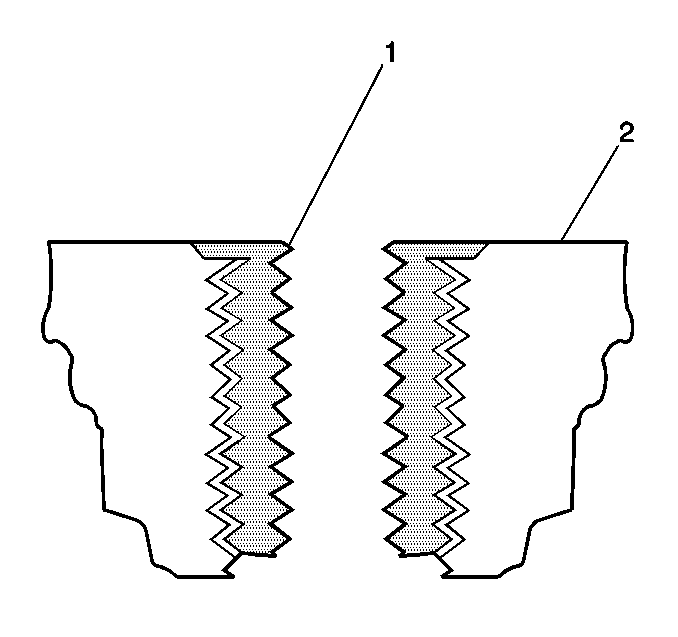
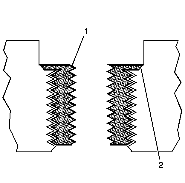
When installed to the proper depth, the flange (1) of the insert will be seated against the counterbore of the drilled/tapped hole and just below the surface (2) of the base material.
- Drill out the threads of the damaged hole.
- Using compressed air, clean out any chips.
- Counterbore the drilled hole to the full depth permitted by the tool (1).
- Using compressed air, clean out any chips.
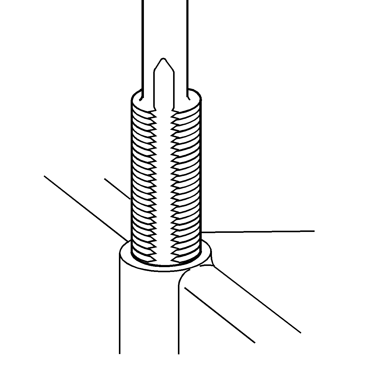
- Using a suitable tapping wrench, tap the threads of the drilled hole by hand only.
- Using compressed air, clean out any chips.
- Spray cleaner GM P/N 12346139, GM P/N 12377981 (Canadian P/N 10953463) or equivalent into the tapped hole.
- Using compressed air, clean out any chips.
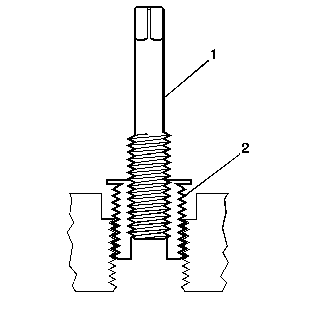
- Lubricate the threads of the driver installation tool (2) with the J 42385-110 (1).
- Install the insert (2) onto the driver installation tool (1).
- Apply threadlock sealant GM P/N 12345493, (Canadian P/N 10953488), J 42385-109, LOCTITE 277® or equivalent (1) to the insert OD threads (2).
- Install the insert (2) into the tapped hole by hand only.
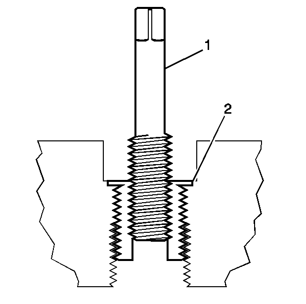
- Install the insert until the flange (2) of the insert contacts the counterbored surface.
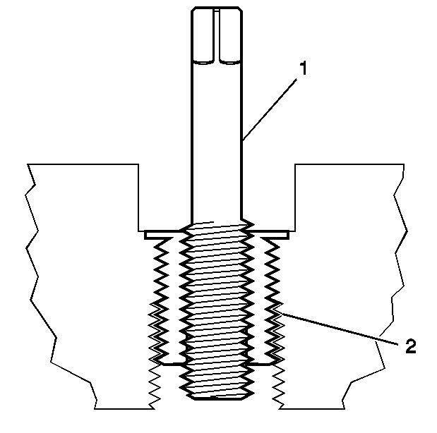
- Continue to rotate the driver installation tool (1) through the insert (2).
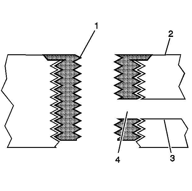
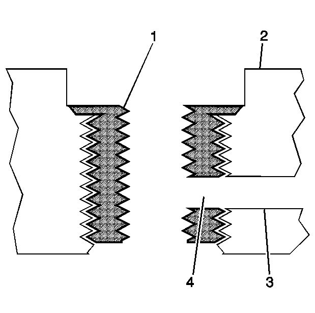
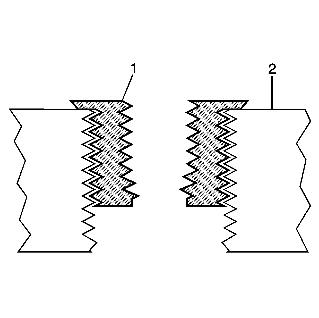
- Inspect the insert for proper installation into the tapped hole. A properly installed insert (1) will be either flush or slightly below flush with the surface of the base material (2).
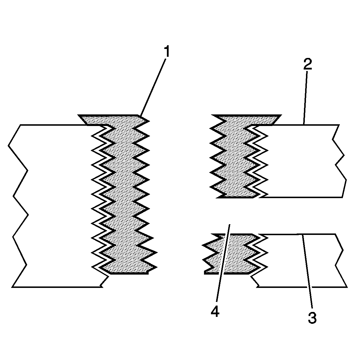
- Any installed insert that restricts or blocks an oil or engine coolant passage (3) will need to have the oil or engine coolant passage drilled out (4) to the original size of the oil or engine coolant passage. After drilling the restriction or blockage, clean out any chips and thread the installation driver tool through the insert again to remove any burrs caused by the drilling of the oil or engine coolant passage.
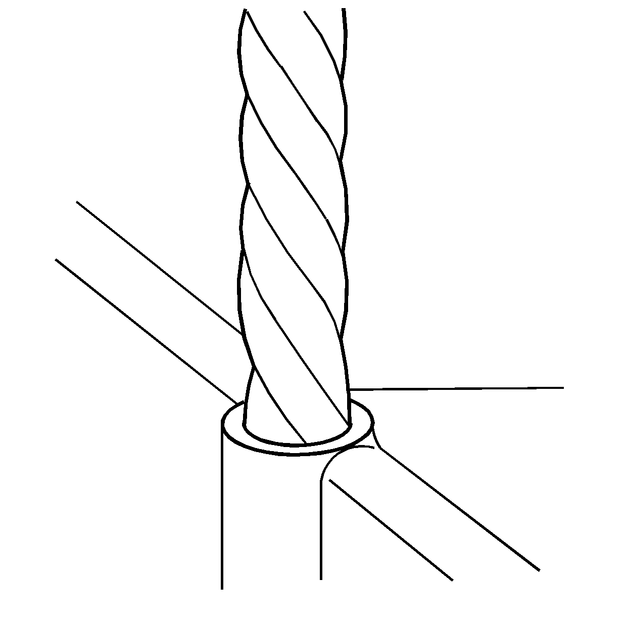
Important:
• During the drilling process, it is necessary to repeatedly remove the drill and clean chips from the hole and the flutes of the drill. • Do NOT drill any further than the original hole depth.
Specifications
| • | M6 inserts require a minimum drill depth of 15 mm (0.59 in). |
| • | M8 inserts require a minimum drill depth of 20 mm (0.79 in). |
| • | M10 inserts require a minimum drill depth of 23.5 mm (0.93 in). |
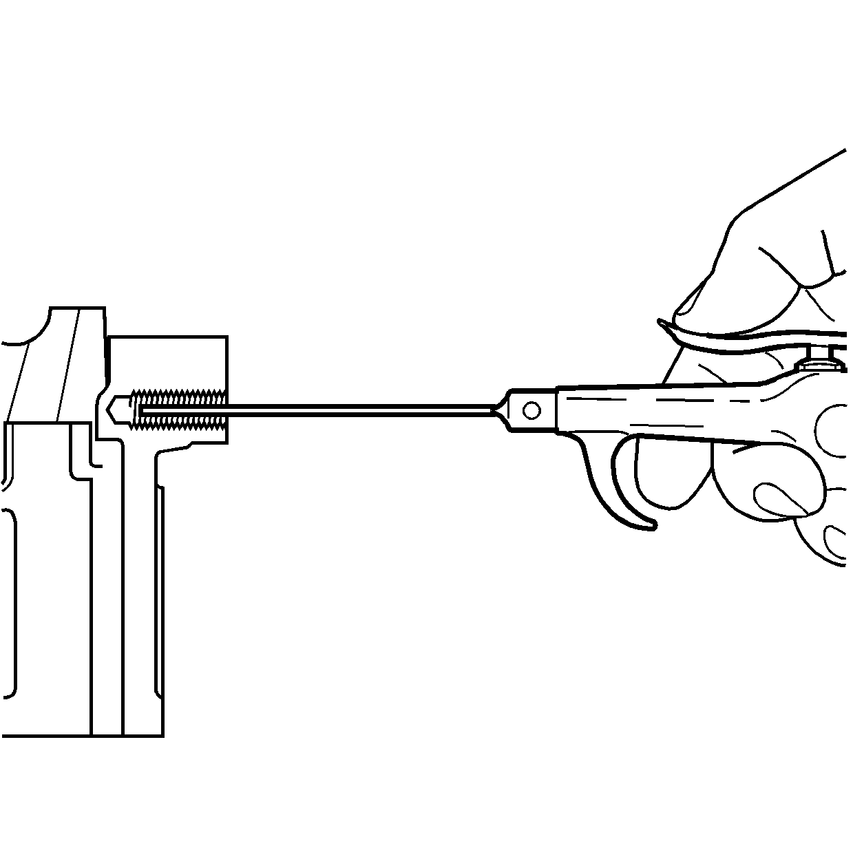
Important: All chips must be removed from the drilled hole prior to tapping.
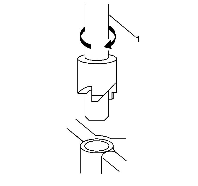
Important: A properly counterbored hole will show a slight burnishing on the surface of the base material for 360 degrees around the drilled hole.

Important: All chips must be removed from the drilled hole prior to tapping.
Important:
• During the tapping process, it is necessary to repeatedly remove the tap and clean chips from the hole and the flutes of the tap. • Ensure the tap has created full threads at least to the depth equal to the insert length.
Specifications
| • | M6 inserts require a minimum tap depth of 15 mm (0.59 in). |
| • | M8 inserts require a minimum tap depth of 20 mm (0.79 in). |
| • | M10 inserts require a minimum tap depth of 23.5 mm (0.93 in). |

Important: All chips must be removed from the tapped hole prior to insert installation.
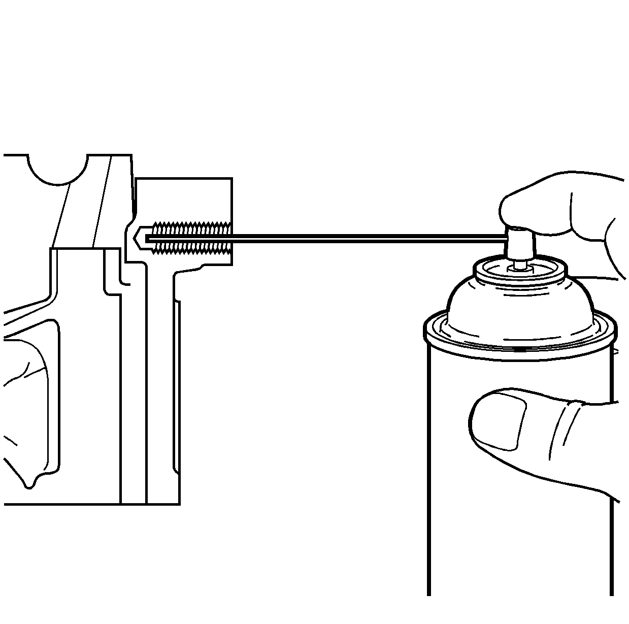

Important: All chips must be removed from the tapped hole prior to insert installation.
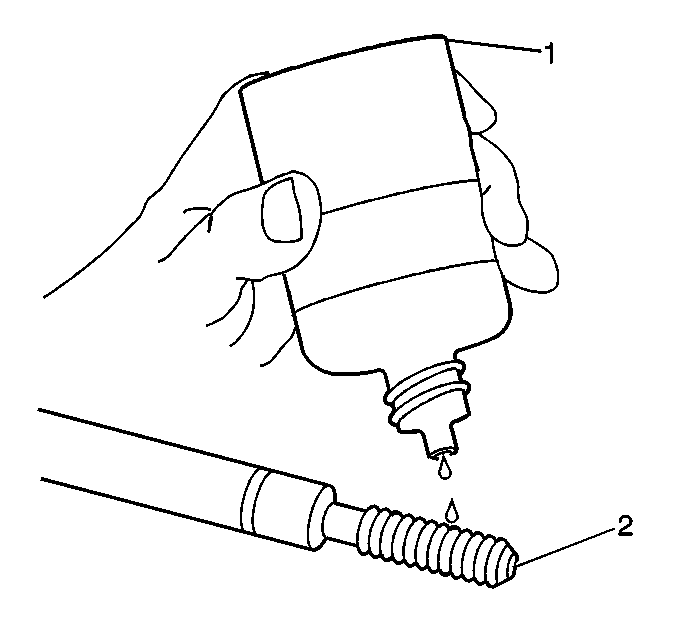
Important: Do not allow oil or other foreign material to contact the outside diameter (OD) of the insert.
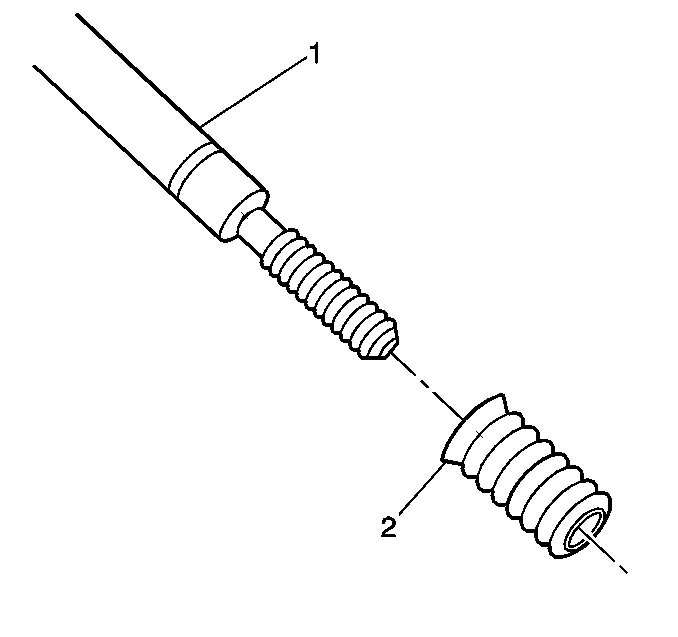
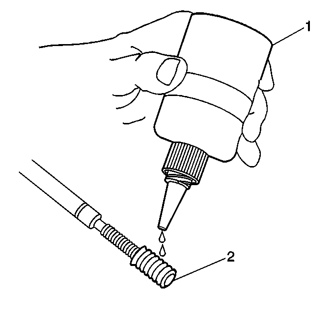
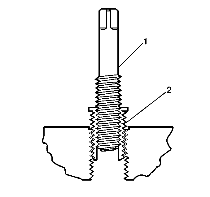
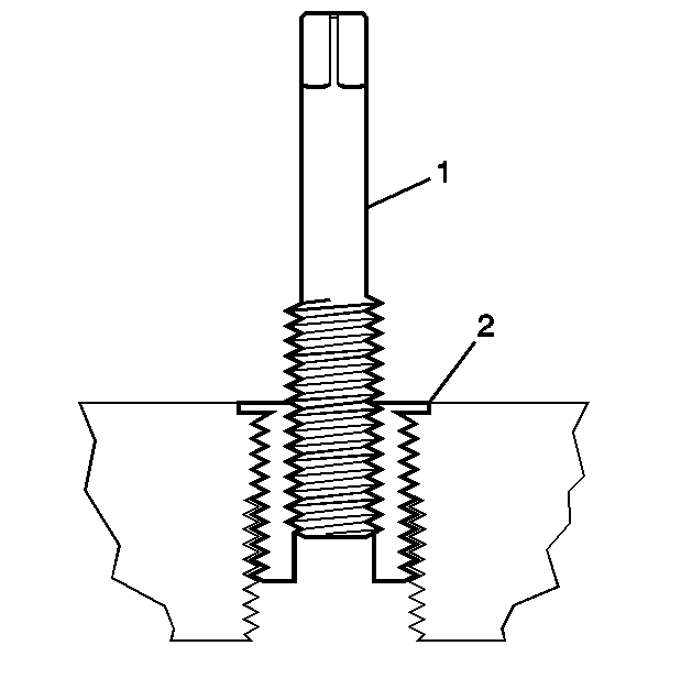
Important: If the insert will not thread down until the flange contacts the counterbored surface, remove the insert immediately with a screw extracting tool and inspect the tapped hole for any remaining chips and/or improper tapping.
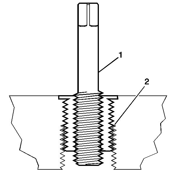
Important: The driver installation tool will tighten up before screwing completely through the insert. This is acceptable. The threads at the bottom of the insert are being formed and the insert is mechanically locking the insert into the base material threads.

Recessed Thread Repair
Caution: Refer to Safety Glasses Caution in the Preface section.
Important:
• The use of a cutting type fluid GM P/N 1052864, (Canadian P/N 992881), WD 40® or equivalent is recommended when performing the drilling, counterboring and tapping procedures. • Do NOT remove the original stop collar from a counterbore drill.
When installed to the proper depth, the flange of the insert (1) will be seated against the counterbore (2) of the drilled/tapped hole.
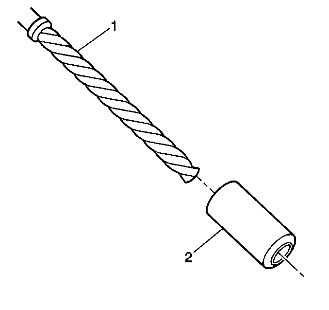
- Install a stop collar (2) on the counterbore drill (1), if required.
- Drill out the threads of the damaged hole.
- Using compressed air, clean out any chips.
- Using a suitable tapping wrench, tap the threads of the drilled hole by hand only.
- Using compressed air, clean out any chips.
- Spray cleaner GM P/N 12346139, GM P/N 12377981 (Canadian P/N 10953463) or equivalent into the tapped hole.
- Using compressed air, clean out any chips.
- Lubricate the threads of the driver installation tool (2) with the J 42385-110 (1).
- Install the insert (2) onto the driver installation tool (1).
- Apply threadlock sealant GM P/N 12345493, (Canadian P/N 10953488), J 42385-109, LOCTITE 277® or equivalent (1) to the insert OD threads (2).
- Install the insert (2) into the tapped hole by hand only.
- Install the insert until the flange (2) of the insert contacts the counterbored surface.
- Continue to rotate the driver installation tool (1) through the insert (2).
- Inspect the insert (1) for proper installation (2) into the tapped hole.
- Any installed insert that restricts or blocks an oil or engine coolant passage (3) will need to have the oil or engine coolant passage drilled out (4) to the original size of the oil or engine coolant passage. After drilling the restriction or blockage, clean out any chips and thread the installation driver tool through the insert again to remove any burrs caused by the drilling of the oil or engine coolant passage.

Important:
• During the drilling process, it is necessary to repeatedly remove the drill and clean chips from the hole and the flutes of the drill. • Drill the hole until the stop collar contacts the surface of the base material.

Important: All chips must be removed from the drilled hole prior to tapping.

Important:
• During the tapping process, it is necessary to repeatedly remove the tap and clean chips from the hole and the flutes of the tap. • Ensure the tap has created full threads at least to the depth equal to the insert length.

Important: All chips must be removed from the tapped hole prior to insert installation.


Important: All chips must be removed from the tapped hole prior to insert installation.

Important: Do not allow oil or other foreign material to contact the outside diameter (OD) of the insert.


Important: If the insert will not thread down until the flange contacts the counterbored surface remove the insert immediately with a screw extracting tool and inspect the tapped hole for any remaining chips and/or improper tapping.
Important: The driver installation tool will tighten up before screwing completely through the insert. This is acceptable. The threads at the bottom of the insert are being formed and the insert is mechanically locking the insert into the base material threads.

Tapered Pipe Thread Repair
The thread repair insert for tapered pipe threads is coated with a clear silver zinc coating.
Caution: Refer to Safety Glasses Caution in the Preface section.
Important: The use of a cutting type fluid GM P/N 1052864, (Canadian P/N 992881), WD 40® or equivalent is recommended when performing the drilling, counterboring and tapping procedures.
When installed to the proper depth, the flange (1) of the insert will be seated against surface (2) of the base material of the drilled/tapped hole.
- Drill out the threads of the damaged hole.
- Using compressed air, clean out any chips.
- Using a suitable tapping wrench, tap the threads of the drilled hole by hand only.
- Tap the drilled hole until the threads at the top of the tap (2) are down to the surface of the base material.
- Using compressed air, clean out any chips.
- Spray cleaner GM P/N 12346139, GM P/N 12377981 (Canadian P/N 10953463) or equivalent into the tapped hole.
- Using compressed air, clean out any chips.
- Lubricate the threads of the driver installation tool (2) with the J 42385-110 (1).
- Install the insert (2) onto the driver installation tool (1).
- Apply threadlock sealant GM P/N 12345493, (Canadian P/N 10953488), J 42385-109, LOCTITE 277® or equivalent (1) to the insert OD threads (2).
- Install the insert (2) into the tapped hole by hand only.
- Install the insert until the flange (2) of the insert contacts the surface of the base material.
- Continue to rotate the driver installation tool (1) until the top of the threaded section (2) is level with the top of the insert (3).
- Inspect the insert (1) for proper installation (2) into the tapped hole.
- Any installed insert that restricts or blocks an oil or engine coolant passage (3) will need to have the oil or engine coolant passage drilled out (4) to the original size of the oil or engine coolant passage. After drilling the restriction or blockage, clean out any chips and thread the installation driver tool through the insert again to remove any burrs caused by the drilling of the oil or engine coolant passage.

Important:
• During the drilling process, it is necessary to repeatedly remove the drill and clean chips from the hole and the flutes of the drill. • Drill the hole until the stop collar contacts the surface of the base material.

Important: All chips must be removed from the drilled hole prior to tapping.

Important:
• During the tapping process, it is necessary to repeatedly remove the tap and clean chips from the hole and the flutes of the tap. • Ensure the tap has created full threads at least to the depth equal to the insert length.
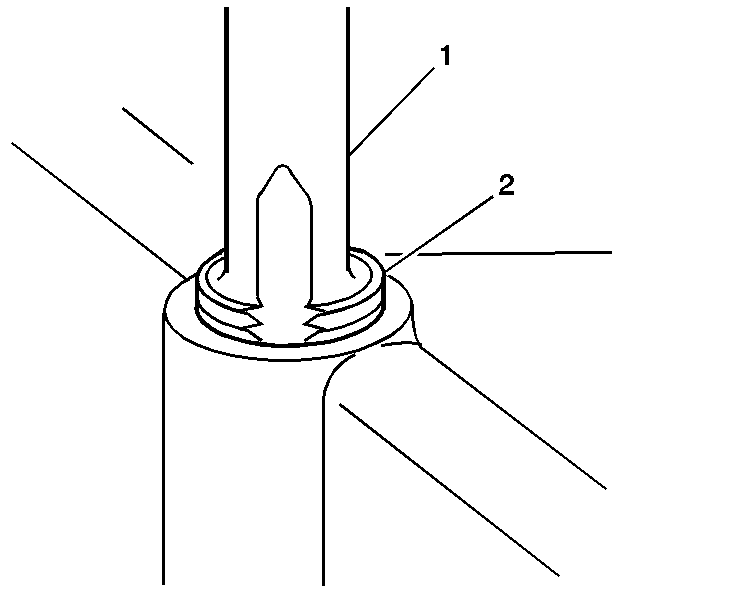

Important: All chips must be removed from the tapped hole prior to insert installation.


Important: All chips must be removed from the tapped hole prior to insert installation.

Important: Do not allow oil or other foreign material to contact the outside diameter (OD) of the insert.


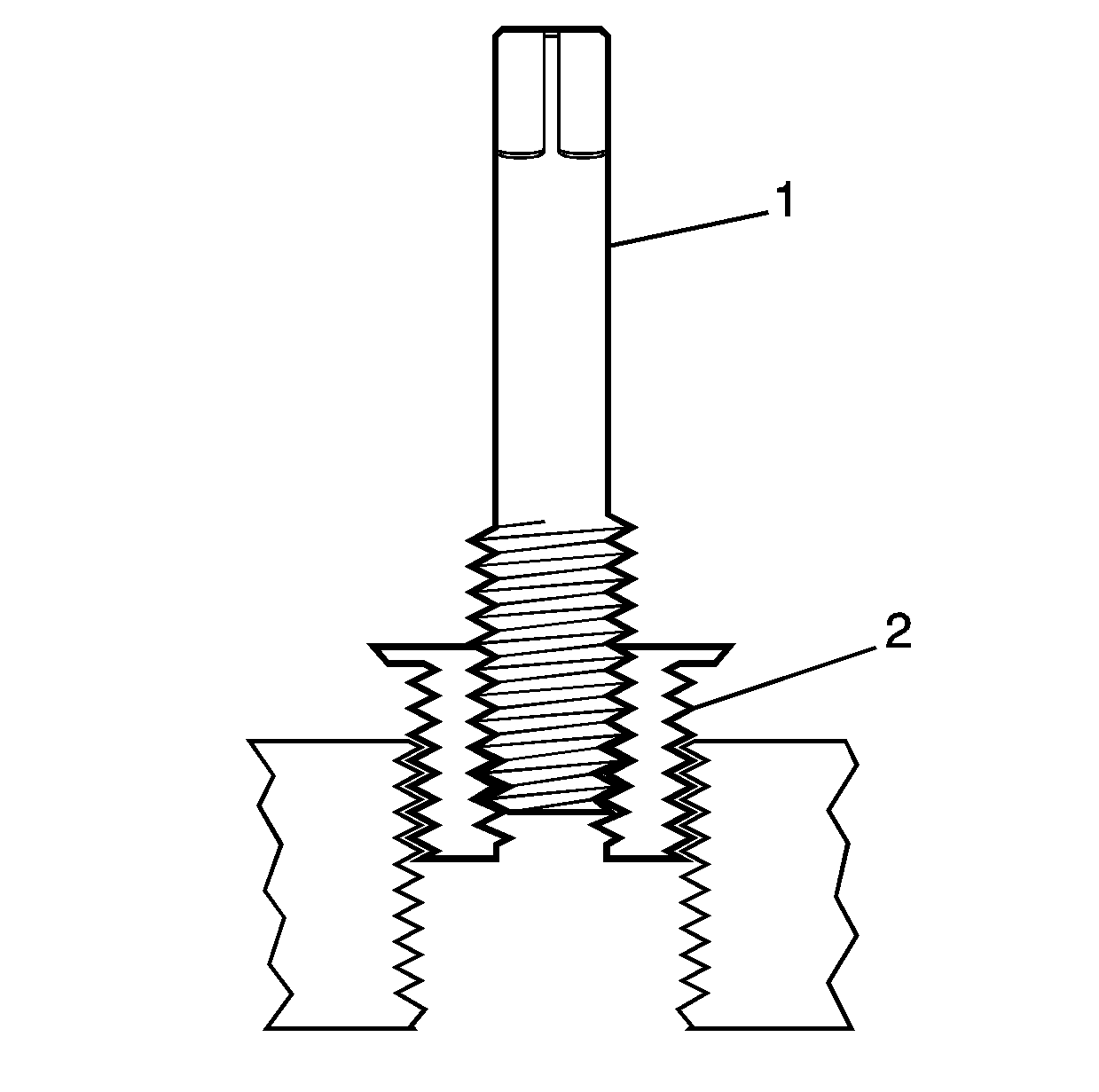
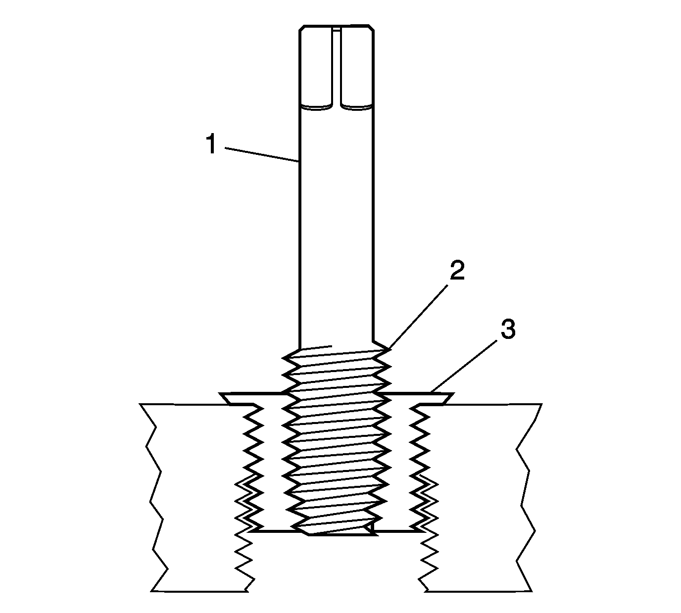
Important: If the insert will not thread down until the flange contacts the surface of the base material remove the insert immediately with a screw extracting tool and inspect the tapped hole for any remaining chips and/or improper tapping.
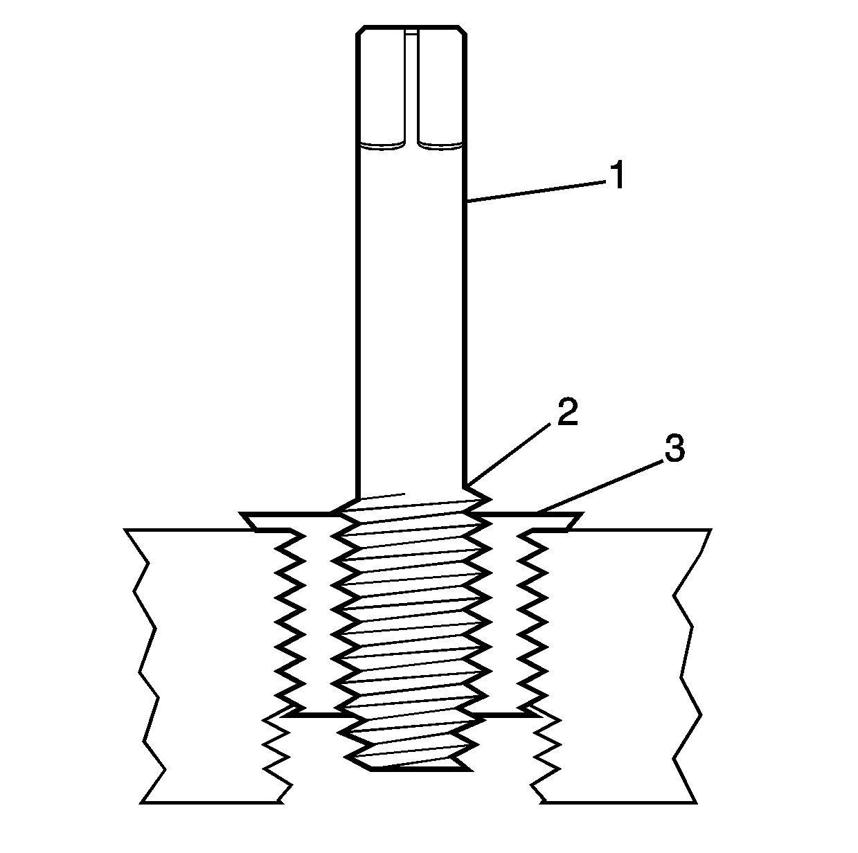
Important: The driver installation tool will tighten up before screwing completely through the insert. This is acceptable. The threads at the bottom of the insert are being formed and the insert is mechanically locking the insert into the base material threads.

Cylinder Head Bolt Hole Thread Repair
Special Tools
| • | J 42385-700 High Feature Thread Repair Kit |
| • | J 42385-2000 Thread Insert Kit |
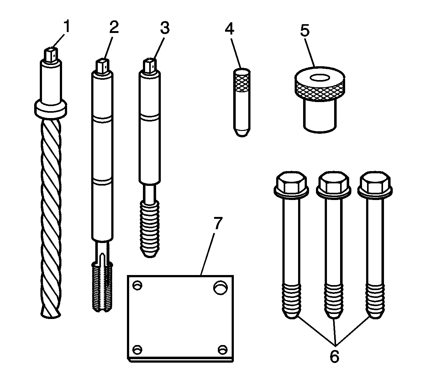
The cylinder head bolt hole thread repair tooling are in the kits J 42385-2000 and J 42385-700 . The cylinder head bolt hole thread repair components consist of the following:
| • | J 42385-723 Drill (1) |
| • | J 42385-724 Tap (2) |
| • | J 42385-725 Installation driver (3) |
| • | J 42385-303 Alignment pin (4) |
| • | J 42385-302 Bushing (5) |
| • | J 42385-733 Bolts (6) |
| • | J 42385-401 Fixture plate (7) |
Caution: Refer to Safety Glasses Caution in the Preface section.
Important:
• Remove the fixture plate prior to installing the insert with the installer tool. • The use of a cutting type fluid GM P/N 1052864 (Canadian P/N 992881) WD 40®; or equivalent is recommended when performing the drilling, counterboring and tapping procedures.
When installed to the proper depth, the flange of the insert will be seated against the counterbore of the drilled/tapped hole.
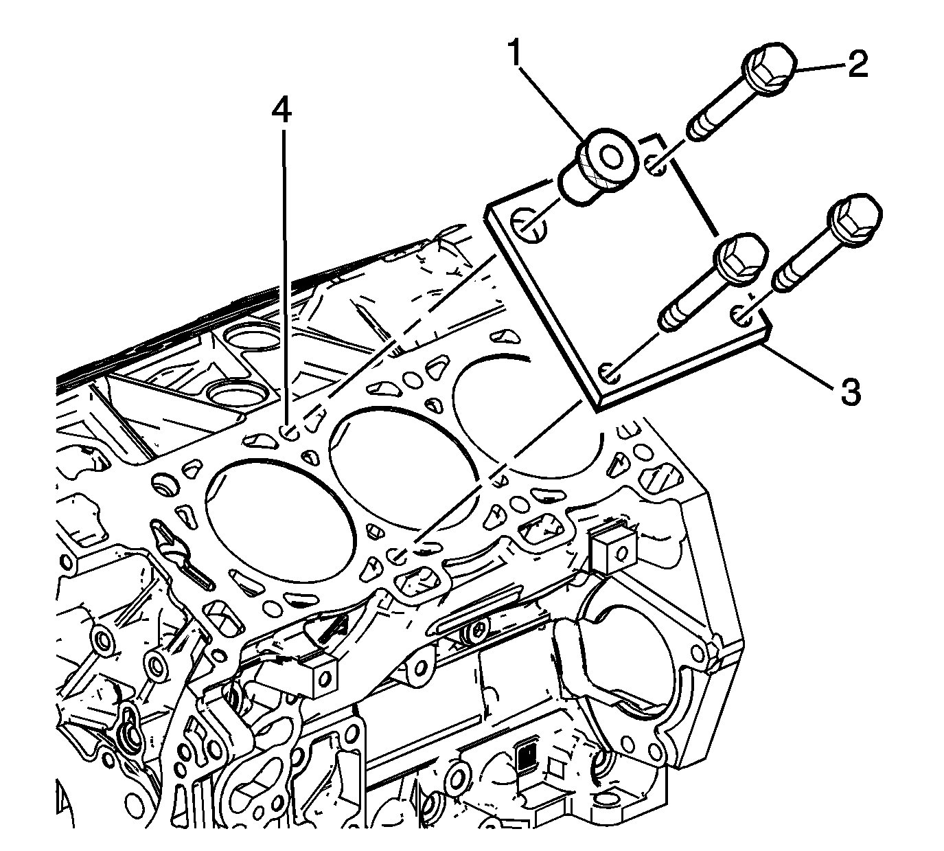
- Position the fixture plate (3) with the bushing (1) installed over the cylinder head bolt hole to be repaired (4).
- Loosely install the fixture plate bolts (2) into the remaining cylinder head bolt holes.
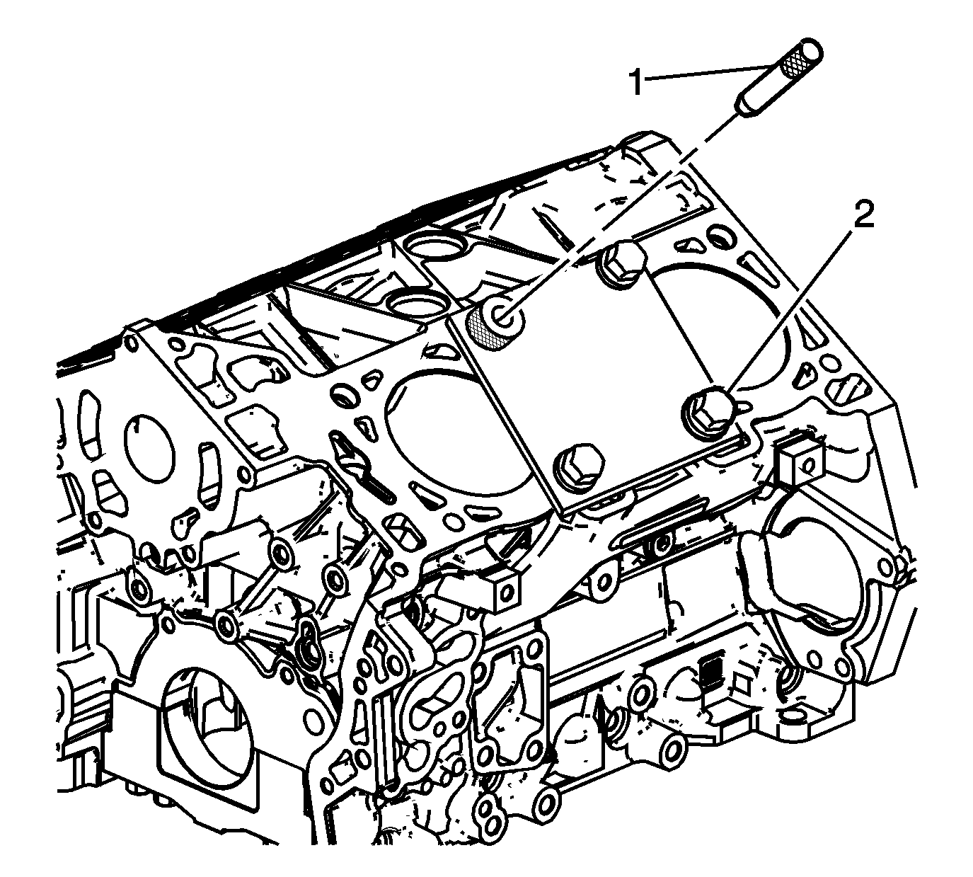
- Position the alignment pin (1) through the bushing and into the cylinder head bolt hole.
- With the alignment pin in the desired cylinder head bolt hole, tighten the fixture retaining bolts (2).
- Remove the alignment pin (1) from the cylinder head bolt hole.
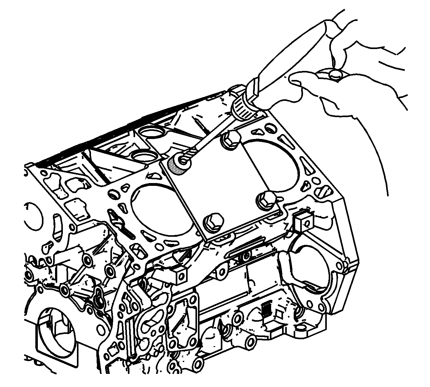
- Drill out the threads of the damaged hole.
- Using compressed air, clean out any chips.
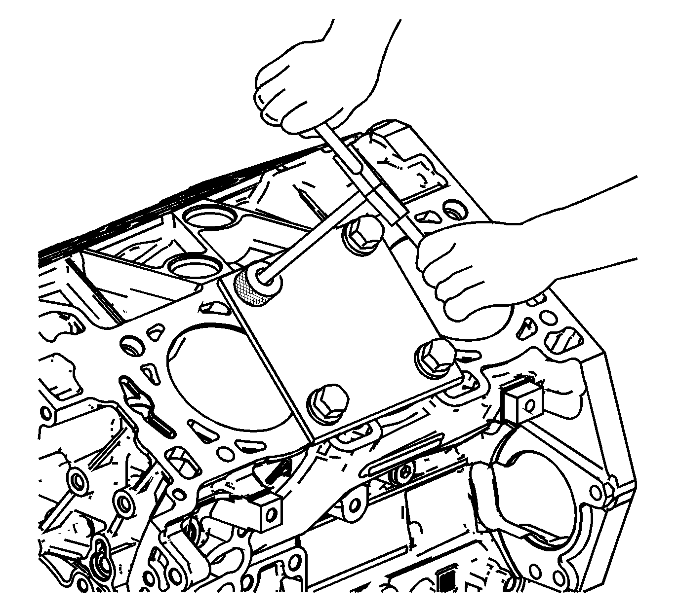
- Using a suitable tapping wrench, tap the threads of the drilled hole by hand only.
- In order to tap the new threads for the insert to the proper depth, rotate the tap into the cylinder head bolt hole until the mark (3) on the tap aligns with the top of the drill bushing (2).
- Remove the fixture plate bolts (2).
- Remove the fixture plate (3) and bushing (1).
- Using compressed air, clean out any chips.
- Spray cleaner GM P/N 12346139, GM P/N 12377981 (Canadian P/N 10953463) or equivalent into the tapped hole.
- Using compressed air, clean out any chips.
- Lubricate the threads of the driver installation tool (2) with the J 42385-110 (1).
- Install the insert (2) onto the driver installation tool (1).
- Apply threadlock sealant GM P/N 12345493, (Canadian P/N 10953488), J 42385-109, LOCTITE 277®; or equivalent (1) to the insert OD threads (2).
- Install the insert and installation driver (1) into the tapped hole by hand only.
- Start the insert into the threaded hole.
- Install the insert until the flange of the insert contacts the counterbored surface.
- Continue to rotate the driver installation tool through the insert.
- In order to completely form the new threads in the insert, rotate the driver installation tool through the insert until the mark (1) on the driver installation tool aligns with the surface of the engine block deck (2).
- Inspect the insert for proper installation into the tapped hole.
Important:
• During the drilling process, it is necessary to repeatedly remove the drill and clean chips from the hole and the flutes of the drill. • Drill the hole until the stop collar contacts the top of the drill bushing.

Important: All chips must be removed from the drilled hole prior to tapping.
Important:
• During the tapping process, it is necessary to repeatedly remove the tap and clean chips from the hole and the flutes of the tap. • Ensure the tap has created full threads at least to the depth equal to the insert length.
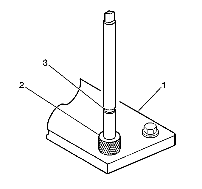

Important: Remove the fixture plate prior to installing the insert with the installer tool.

Important: All chips must be removed from the tapped hole prior to insert installation.


Important: All chips must be removed from the tapped hole prior to insert installation.

Important: Do not allow oil or other foreign material to contact the outside diameter (OD) of the insert.


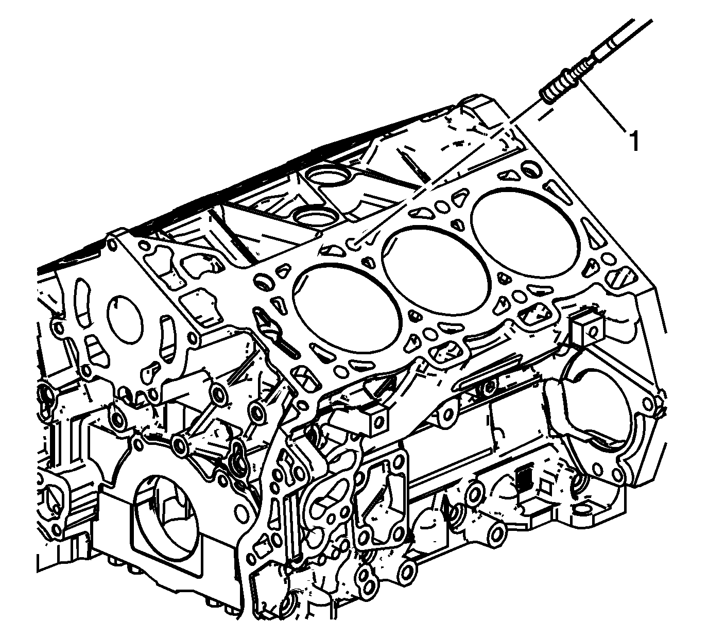
Important: If the insert will not thread down until the flange contacts the counterbored surface remove the insert immediately with a screw extracting tool and inspect the tapped hole for any remaining chips and/or improper tapping.
Important: The driver installation tool will tighten up before screwing completely through the insert. This is acceptable. The threads at the bottom of the insert are being formed and the insert is mechanically locking the insert into the base material threads.
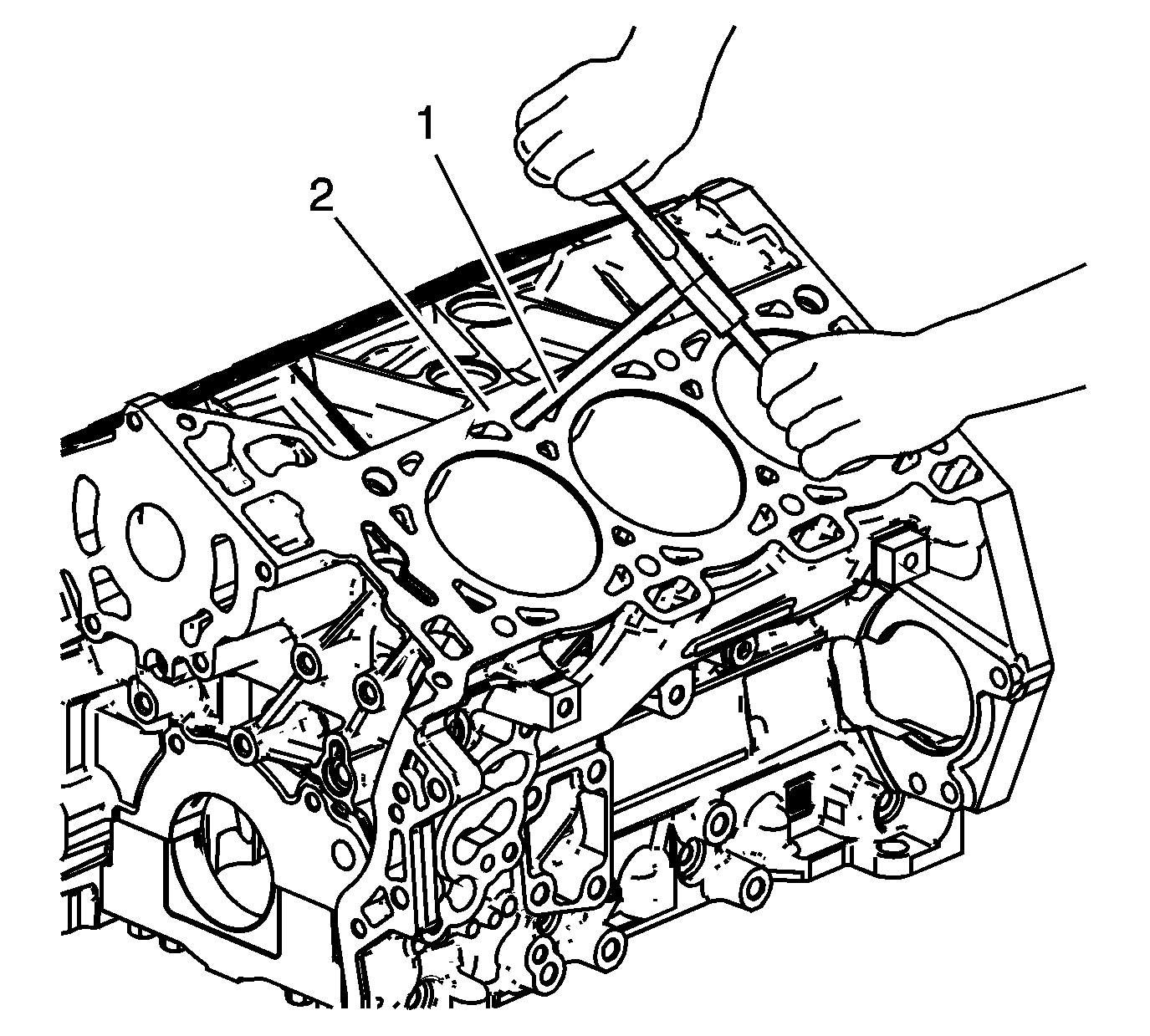
Crankshaft Main Bolt Hole Thread Repair
Special Tools
| • | J 42385-700 High Feature Thread Repair Kit |
| • | J 42385-2000 Thread Insert Kit |
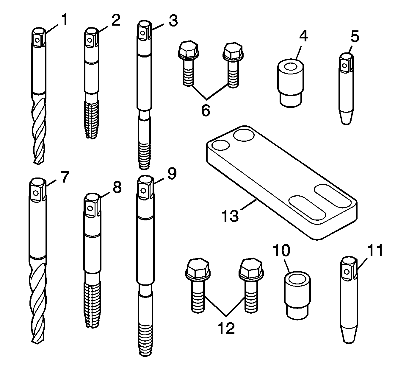
Important:
• In order to repair some crankshaft main bolt holes it will be necessary to mount the fixture plate upside down. • Do NOT remove the fixture plate prior to installing the insert with the installation driver. The fixture plate remains in position throughout the thread repair process.
The crankshaft main bearing bolt hole thread repair tooling are in the kits J 42385-2000 and J 42385-700 . The crankshaft main bearing bolt hole thread repair components consist of the following:
| • | J 42385-702 Drill (1) for outboard holes |
| • | J 42385-703 Tap (2) for outboard holes |
| • | J 42385-704 Installation driver (3) for outboard holes |
| • | J 42385-726 Bushing (4) for outboard holes |
| • | J 42385-727 Alignment pin (5) for outboard holes |
| • | J 42385-728 Bolts (6) for outboard holes |
| • | J 42385-720 Drill (7) for inboard holes |
| • | J 42385-721 Tap (8) for inboard holes |
| • | J 42385-722 Installation driver (9) for inboard holes |
| • | J 42385-713 Bushing (10) |
| • | J 42385-308 Alignment pin (11) |
| • | J 42385-734 Bolts (12) |
| • | J 42385-712 Fixture plate (13) |
Outboard Bolt Holes
Caution: Refer to Safety Glasses Caution in the Preface section.
Important:
• Ensure the fixture plate is installed during the machining and installation processes of the insert. • The use of a cutting type fluid GM P/N 1052864, (Canadian P/N 992881), WD 40® or equivalent is recommended when performing the drilling, counterboring and tapping procedures.
When installed to the proper depth, the flange of the insert will be seated against the counterbore of the drilled/tapped hole.
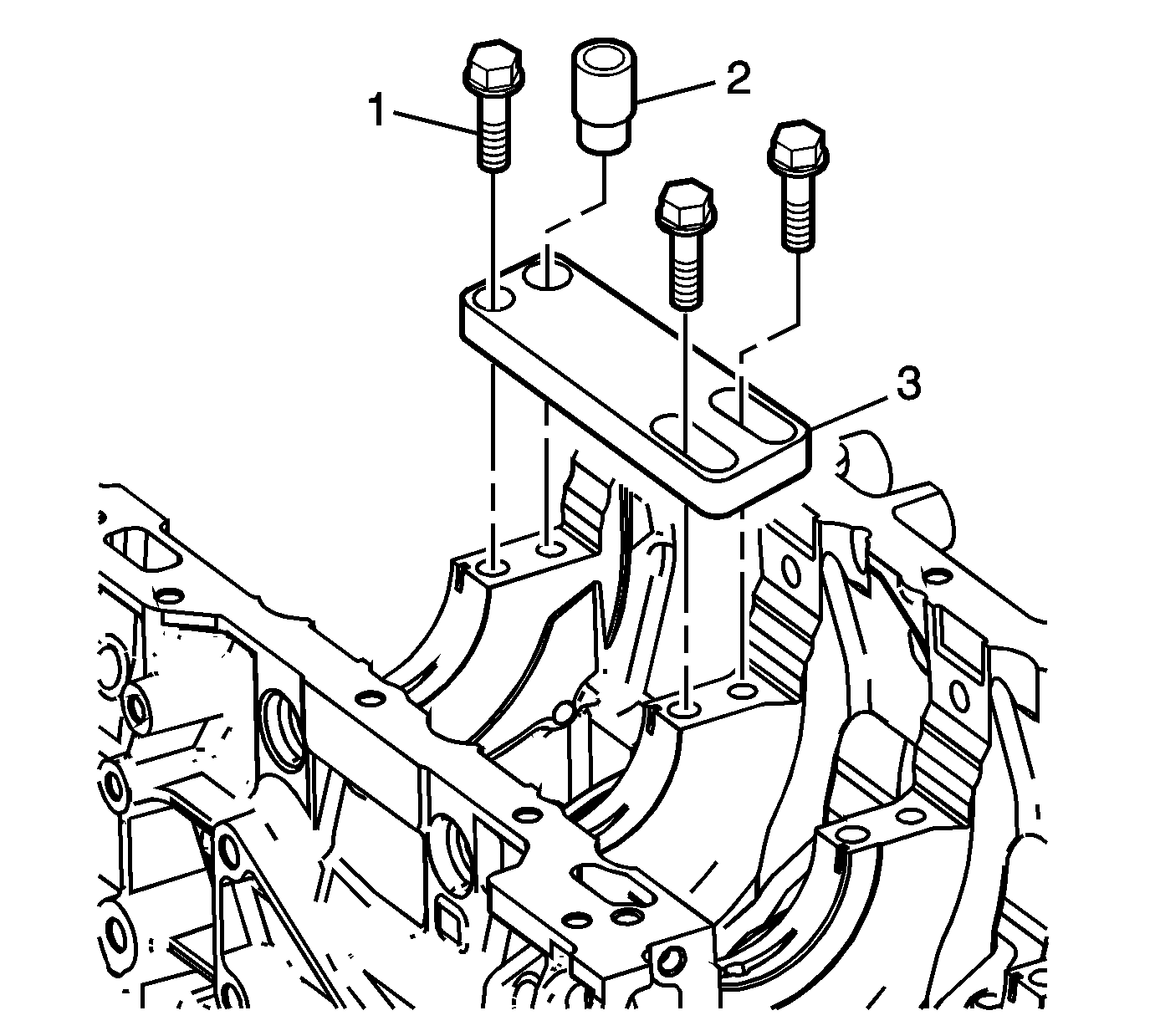
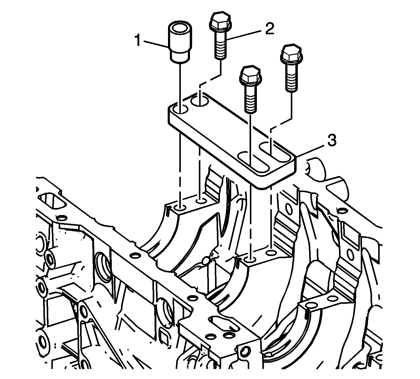
- Position the fixture plate (3) with the bushing (2) installed over the crankshaft main cap bolt hole to be repaired.
- Loosely install the fixture plate bolts (1) into the remaining crankshaft main cap bolt holes.
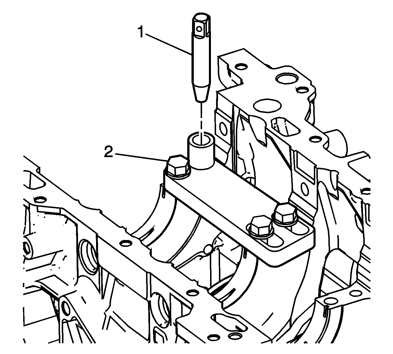
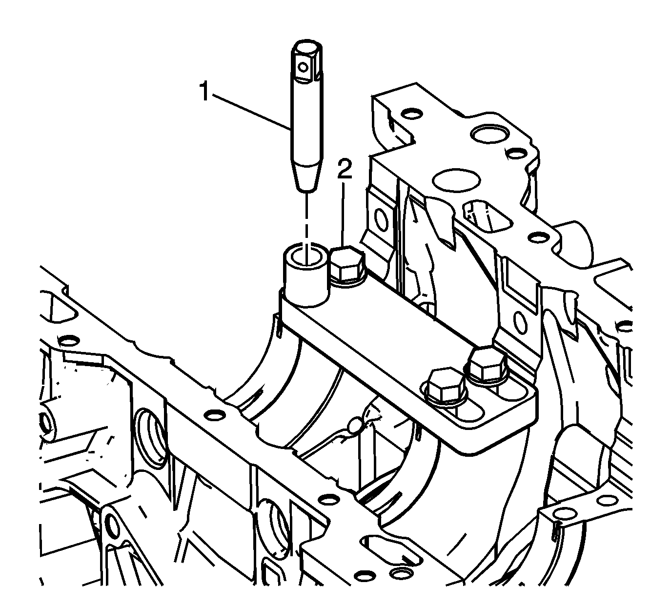
- Position the alignment pin (1) through the bushing and into the crankshaft main cap bolt hole.
- With the alignment pin in the desired crankshaft main cap bolt hole, tighten the fixture retaining bolts (2).
- Remove the alignment pin (1) from the crankshaft main cap bolt hole.
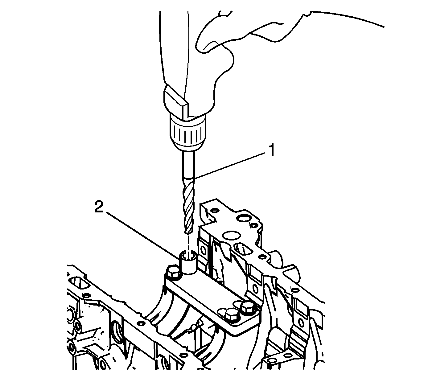
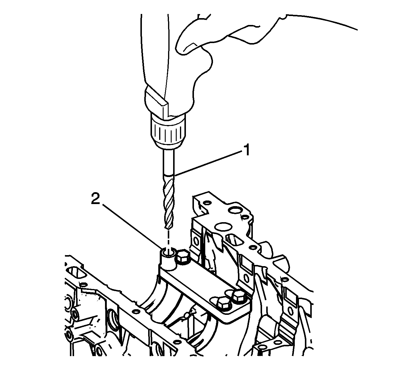
- Drill out the threads of the damaged hole.
- Using compressed air, clean out any chips.
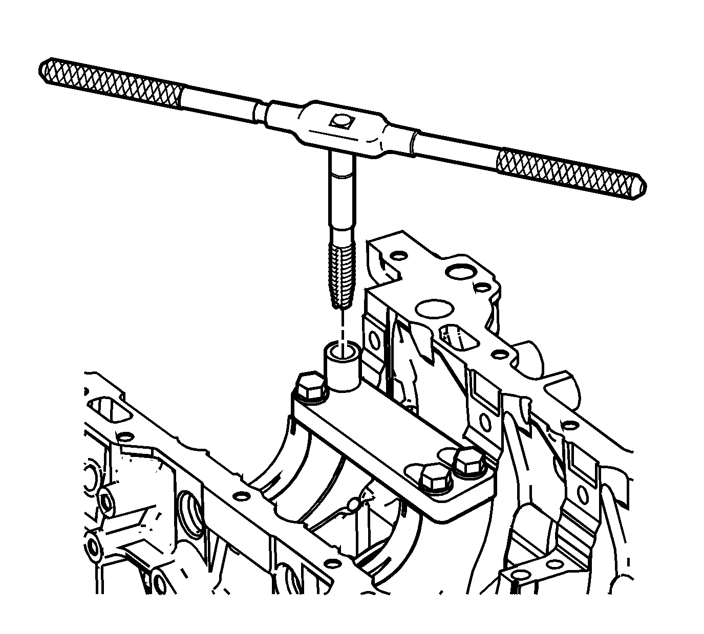
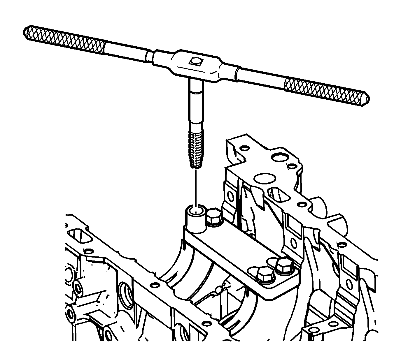
- Using a suitable tapping wrench, tap the threads of the drilled hole by hand only.
- In order to tap the new threads for the insert to the proper depth, rotate the tap into the crankshaft main cap bolt hole until the mark (3) on the tap aligns with the top of the drill bushing (2).
- Using compressed air, clean out any chips.
- Spray cleaner GM P/N 12346139, GM P/N 12377981 (Canadian P/N 10953463) or equivalent into the tapped hole.
- Using compressed air, clean out any chips.
- Lubricate the threads of the driver installation tool (2) with the J 42385-110 (1).
- Install the insert (2) onto the driver installation tool (1).
- Apply threadlock sealant GM P/N 12345493, (Canadian P/N 10953488), J 42385-109, LOCTITE 277®, or equivalent (1) to the insert OD threads (2).
- Install the insert and installation driver into the tapped hole by hand only.
- Start the insert into the threaded hole.
- Install the insert until the flange of the insert contacts the counterbored surface.
- Continue to rotate the driver installation tool through the insert.
- Rotate the driver installation tool until the mark (3) on the driver installation tool aligns with the top of the drill bushing (2).
- Inspect the insert for proper installation into the tapped hole.
- Remove the fixture plate bolts (1).
- Remove the fixture plate (3) and bushing (2).
Important:
• During the drilling process, it is necessary to repeatedly remove the drill and clean chips from the hole and the flutes of the drill. • Drill the crankshaft main bolt hole until the mark (1) on the drill aligns with the top of the drill bushing (2).

Important: All chips must be removed from the drilled hole prior to tapping.
Important:
• Do not remove the fixture plate, ensure the fixture plate is installed during the machining and installation processes of the insert. • During the tapping process, it is necessary to repeatedly remove the tap and clean chips from the hole and the flutes of the tap. • Ensure the tap has created full threads at least to the depth equal to the insert length.


Important: All chips must be removed from the tapped hole prior to insert installation.


Important: All chips must be removed from the tapped hole prior to insert installation.

Important:
• Do not remove the fixture plate, ensure the fixture plate is installed during the installation process of the insert. • Do not allow oil or other foreign material to contact the outside diameter (OD) of the insert.


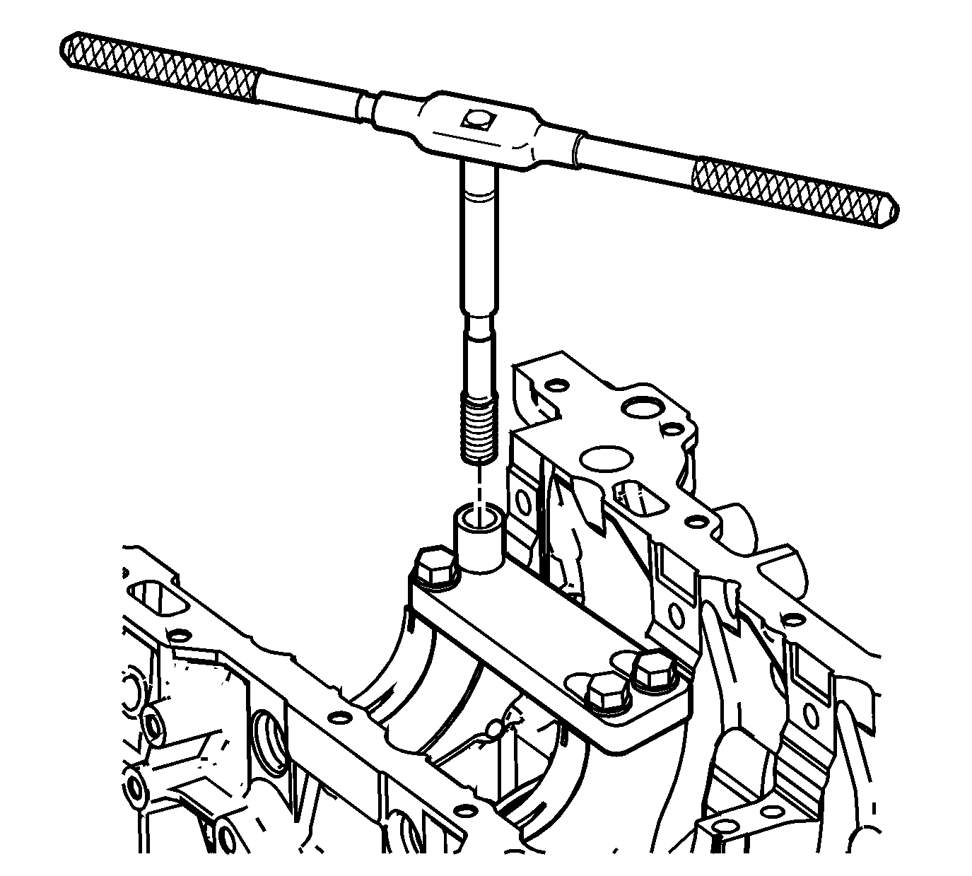
Important: If the insert will not thread down until the flange contacts the counterbored surface remove the insert immediately with a screw extracting tool and inspect the tapped hole for any remaining chips and/or improper tapping.
Important: The driver installation tool will tighten up before screwing completely through the insert. This is acceptable. The threads at the bottom of the insert are being formed and the insert is mechanically locking the insert into the base material threads.


Inboard Bolt Holes
- Position the fixture plate (3) with the bushing (1) installed over the crankshaft main cap bolt hole to be repaired.
- Loosely install the fixture plate bolts (2) into the remaining crankshaft main cap bolt holes.
- Position the alignment pin (1) through the bushing and into the crankshaft main cap bolt hole.
- With the alignment pin in the desired crankshaft main cap bolt hole, tighten the fixture retaining bolts (2).
- Remove the alignment pin (1) from the crankshaft main cap bolt hole.
- Drill out the threads of the damaged hole.
- Using compressed air, clean out any chips.
- Using a suitable tapping wrench, tap the threads of the drilled hole by hand only.
- In order to tap the new threads for the insert to the proper depth, rotate the tap into the crankshaft main cap bolt hole until the mark (3) on the tap aligns with the top of the drill bushing (2).
- Using compressed air, clean out any chips.
- Spray cleaner GM P/N 12346139, GM P/N 12377981 (Canadian P/N 10953463) or equivalent into the tapped hole.
- Using compressed air, clean out any chips.
- Lubricate the threads of the driver installation tool (2) with the J 42385-110 (1).
- Install the insert (2) onto the driver installation tool (1).
- Apply threadlock sealant GM P/N 12345493, (Canadian P/N 10953488), J 42385-109, LOCTITE 277®, or equivalent (1) to the insert OD threads (2).
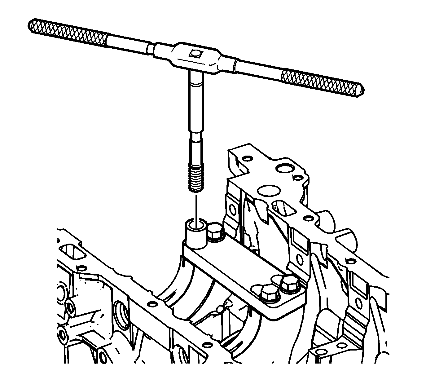
- Install the insert and installation driver into the tapped hole by hand only.
- Start the insert into the threaded hole.
- Install the insert until the flange of the insert contacts the counterbored surface.
- Continue to rotate the driver installation tool through the insert.
- Rotate the driver installation tool until the mark (3) on the driver installation tool aligns with the top of the drill bushing (2).
- Inspect the insert for proper installation into the tapped hole.
- Remove the fixture plate bolts (2).
- Remove the fixture plate (3) and bushing (1).
Caution: Refer to Safety Glasses Caution in the Preface section.
Important:
• Ensure the fixture plate is installed during the machining and installation processes of the insert. • The use of a cutting type fluid GM P/N 1052864, (Canadian P/N 992881), WD 40® or equivalent is recommended when performing the drilling, counterboring and tapping procedures. When installed to the
proper depth, the flange of the insert will be seated against the counterbore of the drilled/tapped hole.
Important:
• During the drilling process, it is necessary to repeatedly remove the drill and clean chips from the hole and the flutes of the drill. • Drill the crankshaft main bolt hole until the mark (1) on the drill aligns with the top of the drill bushing (2).

Important: All chips must be removed from the drilled hole prior to tapping.
Important:
• Do not remove the fixture plate, ensure the fixture plate is installed during the machining and installation processes of the insert. • During the tapping process, it is necessary to repeatedly remove the tap and clean chips from the hole and the flutes of the tap. • Ensure the tap has created full threads at least to the depth equal to the insert length.


Important: All chips must be removed from the tapped hole prior to insert installation.


Important: All chips must be removed from the tapped hole prior to insert installation.

Important:
• Do not remove the fixture plate, ensure the fixture plate is installed during the installation process of the insert. • Do not allow oil or other foreign material to contact the outside diameter (OD) of the insert.


Important: If the insert will not thread down until the flange contacts the counterbored surface remove the insert immediately with a screw extracting tool and inspect the tapped hole for any remaining chips and/or improper tapping.
Important: The driver installation tool will tighten up before screwing completely through the insert. This is acceptable. The threads at the bottom of the insert are being formed and the insert is mechanically locking the insert into the base material threads.


