For 1990-2009 cars only
Special Tools
| • | J 28467-15 Engine Support Adapter |
| • | J 28467-86 Engine Lift Bracket |
| • | J 28467-87 Engine Lift Bracket |
| • | J 28467-B Universal Engine Support Fixture |
Installation Procedure
- Instructions for the right rear J 28467-87 are included at the end of this procedure.
- Remove the fuel injector sight shield. Refer to Fuel Injector Sight Shield Replacement.
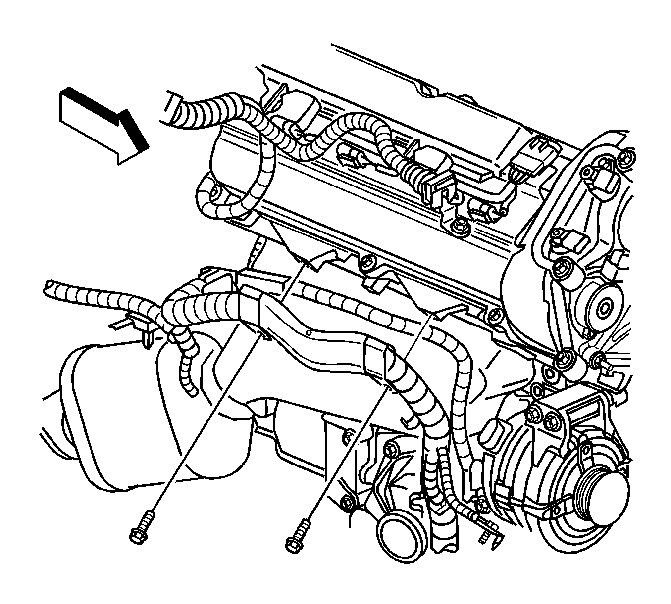
- Remove the wiring harness push pin from the left front cylinder head bolt hole.
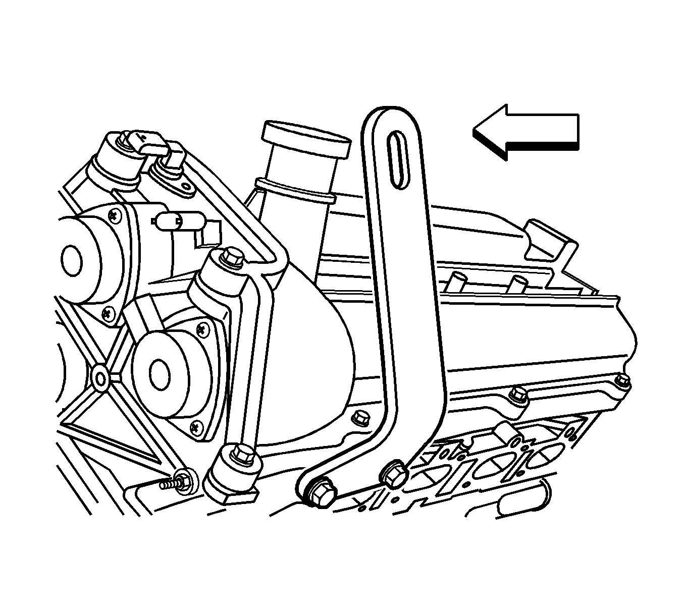
- Install the J 28467-86 to the left cylinder head.
- Remove the front bolt securing the wiring harness bracket to the right cylinder head.
- Install the J 28467-15 to the right cylinder head. The graphic shows the engine removed for clarity.
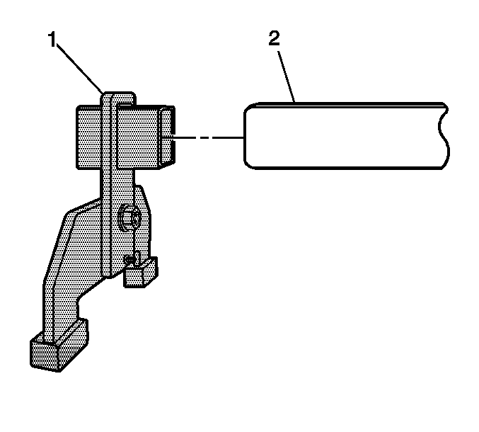
- Assemble a J 28467-501A (1) to each end of the J 28467-518 (2).
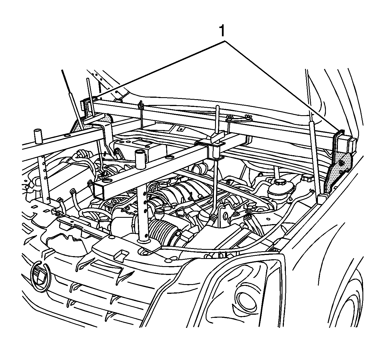
- Position the main support beam and rail support assembly (1) on the fender flange.
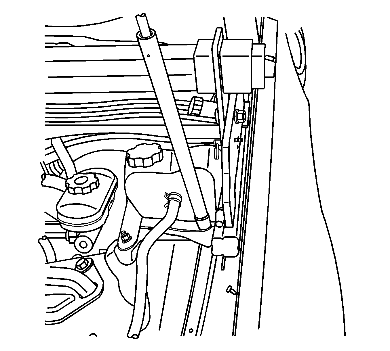
- Ensure that the rear portion of the rail support is resting on the reinforced section of the fender flange.
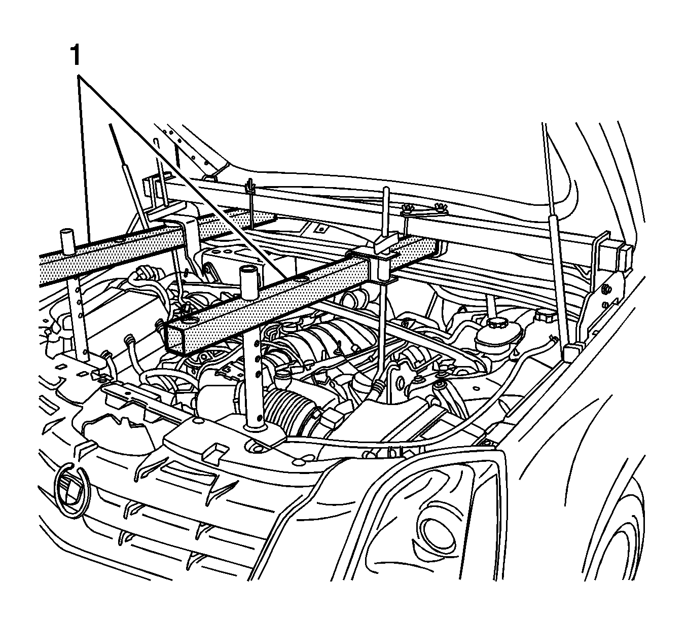
- Assemble a J 28467-16 tube assembly (1) to each end of the J 28467-518, in line with the lift bracket and support bracket, using the J 28467-1 cross brackets.
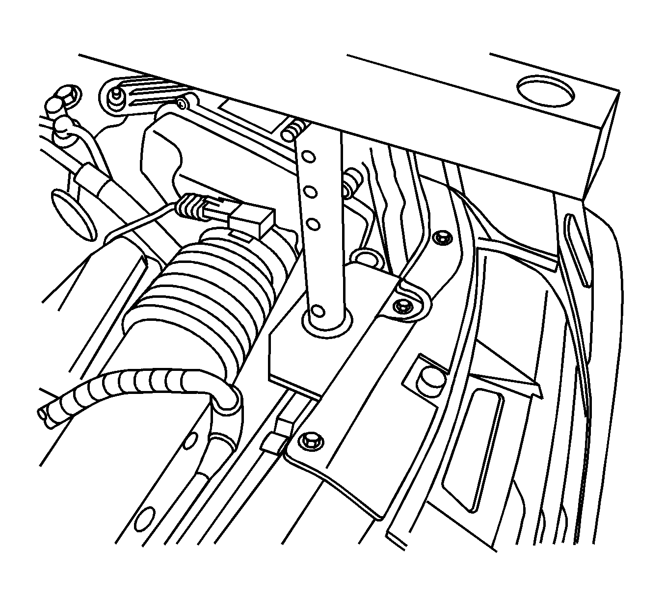
- Install the J 28467-4A front support assemblies to the J 28467-16 using the J 28467-9 quick release pins. Ensure that the J 28467-16 are as level as possible by selecting the appropriate hole for the quick release pins.
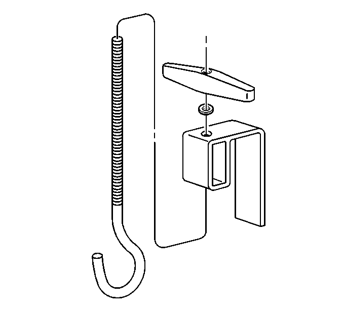
- Install the J 28467-7A , as required, to lift the hook through the J 28467-6A lift hook bracket.
- Install the ½ inch lift hook washer and the J 28467-34 lift hook wing nut onto the J 28467-7A lift hook.
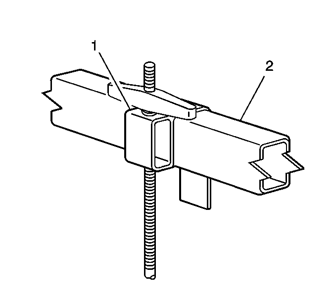
- Install the J 28467-6A (1) over the J 28467-16 (2).
- Adjust the J 28467-6A bracket (1) in order to align the hook with the left J 28467-86 .
- Repeat the previous step for the right J 28467-15 .
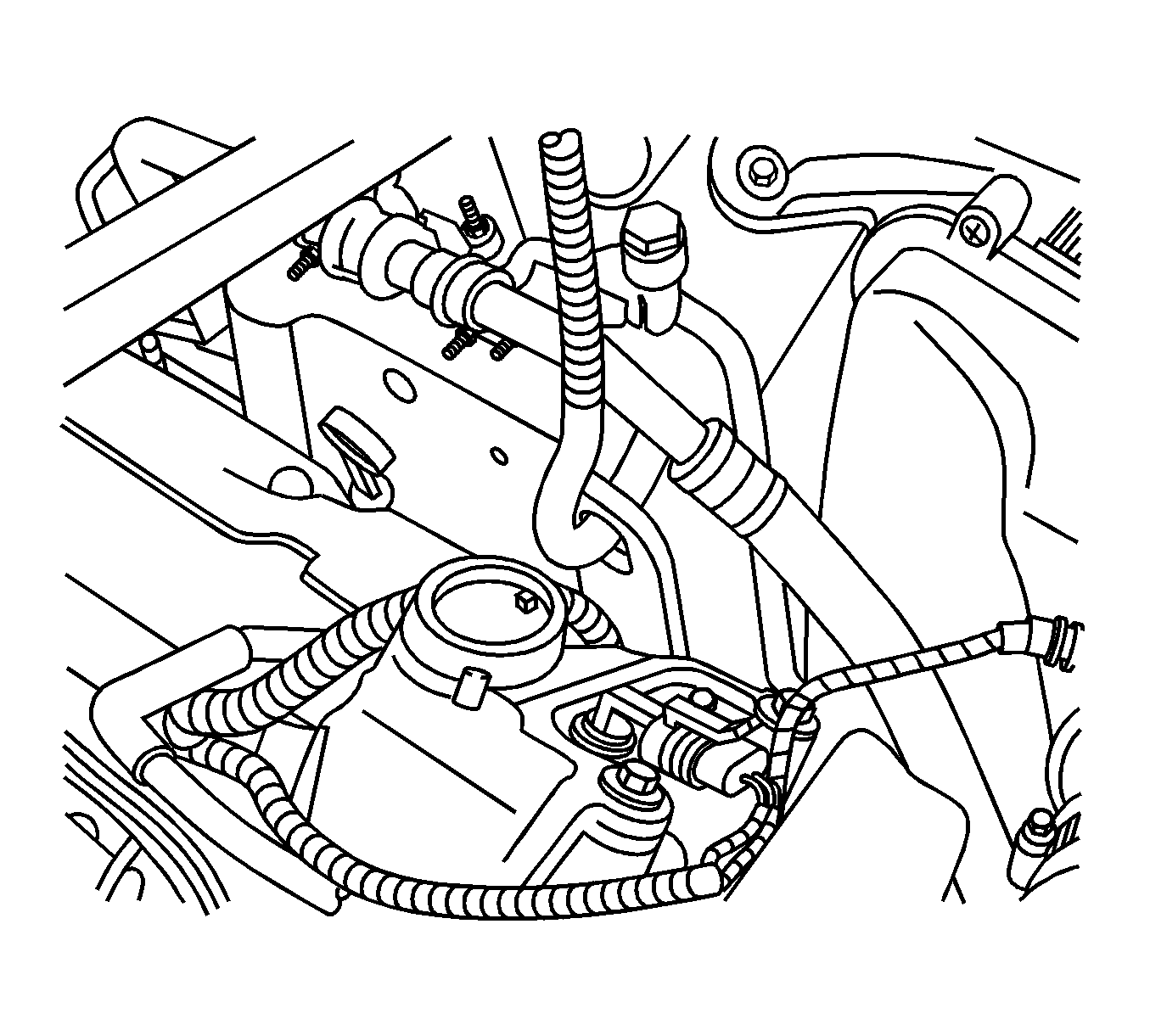
- Install each J 28467-7A through each engine lift bracket and engine support adapter. Ensure that the hooks do not damage the surrounding components.
- Hand-tighten the J 28467-34 securely to remove all slack from the engine support fixture assembly.
- The engine is now supported in vehicle to perform repairs that require front frame removal.
- The J 28467-87 is used to lift the engine once the engine is removed from the vehicle.
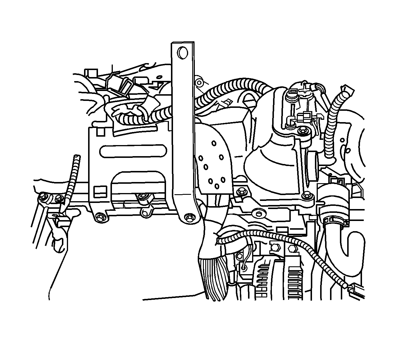
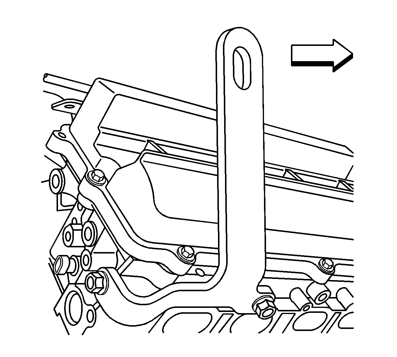
- Remove the ground strap from the right rear cylinder head and bolt the J 28467-87 in position.
- The J 28467-87 and the J 28467-86 can now be used to lift the engine.
Note: The following procedure is for supporting the engine in vehicle. The J 28467-15 is for supporting the engine in vehicle only. It is not intended to be used for lifting the engine once the engine is removed. The J 28467-86 that bolts to the left front cylinder head is used for engine support in vehicle and engine lifting once the engine is removed. The J 28467-87 is only used to lift the engine once the engine is removed from the vehicle. The J 28467-87 can not be used for engine support in vehicle due to limited access to the rear of the right cylinder head in the area where the bracket mounts.
Removal Procedure
- Unscrew the lift hooks (1) and remove them from the lift bracket and the support brackets. Remove the lift hooks from the tube assemblies.
- Remove the front tube and support assemblies from the main support beam.
- Remove the main support beam assembly.
- Remove the J 28467-15 from the right cylinder head.
- Install the front wire harness bracket bolt.
- Remove the J 28467-86 from the left cylinder head.
- Install the push pin securing the wiring harness to the left cylinder head.
- Install the fuel injector sight shield. Refer to Fuel Injector Sight Shield Replacement.

Caution: Refer to Fastener Caution in the Preface section.
Tighten
Tighten the wire harness bracket bolt to 45 N·m (33 lb ft).
