For 1990-2009 cars only
Special Tools
J 43631 Ball Joint Remover
Removal Procedure
- Raise and support the vehicle. Refer to Lifting and Jacking the Vehicle.
- Remove the tire and wheel. Refer to Tire and Wheel Removal and Installation.
- Remove the shock module yoke. Refer to Front Shock Absorber Yoke Replacement.
- Remove the stabilizer shaft link lower retaining nut.
- Remove the stabilizer shaft link from the lower control arm.
- Remove the ABS wire harness from the lower control arm.
- Remove the lower control arm to steering knuckle nut.
- Using the J 43631 , separate the lower control arm from the steering knuckle.
- Loosen the power steering gear retaining bolts and raise the power steering gear.
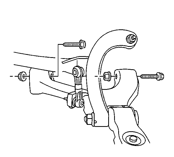
- Remove the lower control arm to cradle nuts.
- Remove the lower control arm to cradle bolts.
- Remove the lower control arm by lowering the lower control arm at the frame and moving the ball stud upwards.
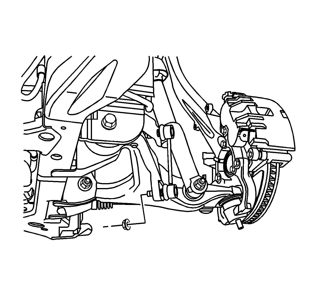
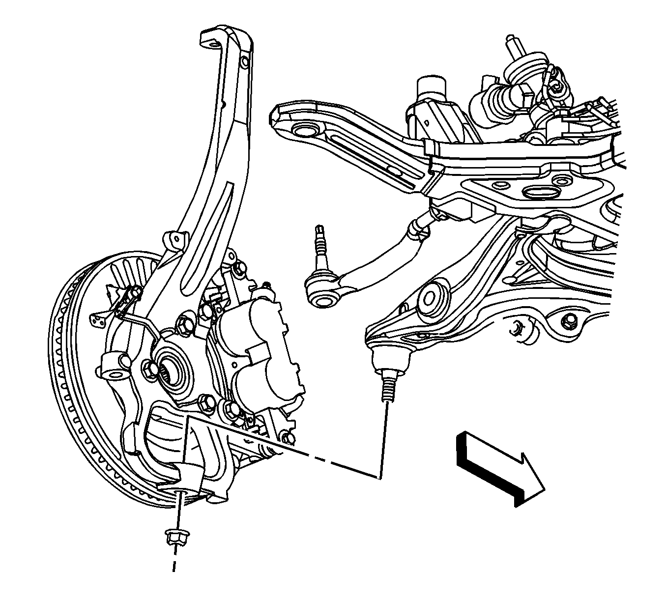
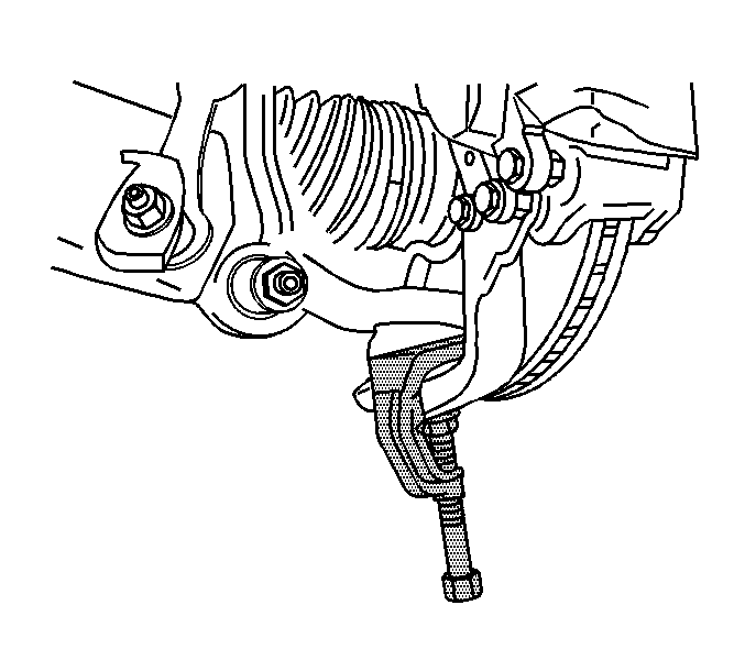
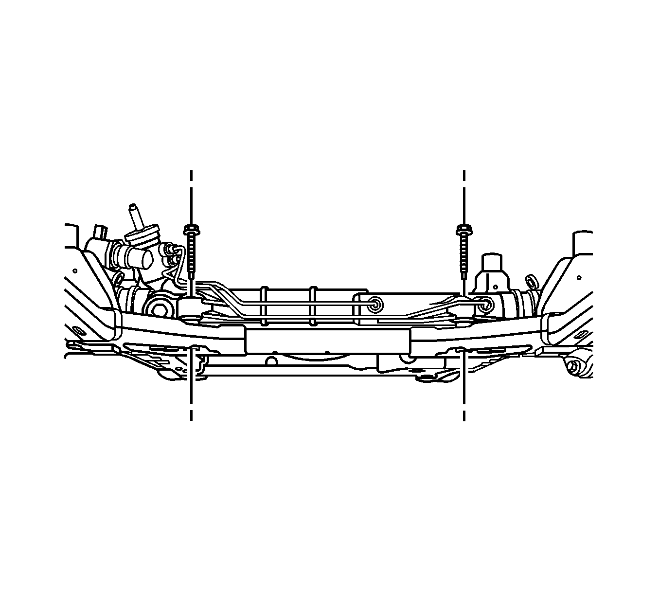
Note: Will need to raise the power steering gear to have clearance when removing the rear lower control arm to frame retaining bolt.
Installation Procedure
- Install the lower control arm by installing the lower control arm of the ball stud and moving the lower control arm up to the cradle.
- Install the lower control arm to cradle bolts.
- Install the lower control arm to cradle nuts.
- Tighten the power steering gear retaining bolts.
- Install the lower control arm to steering knuckle nut.
- Install the ABS wire harness to the lower control arm.
- Install the stabilizer shaft link to the lower control arm.
- Install the stabilizer shaft link lower retaining nut.
- Install the shock module yoke. Refer to Front Shock Absorber Yoke Replacement.
- Install the tire and wheel. Refer to Tire and Wheel Removal and Installation.
- Lower the vehicle.
- Align the front end. Refer to Wheel Alignment Measurement.

Caution: Refer to Fastener Caution in the Preface section.
Tighten
Tighten the nuts to 135 N·m (100 lb ft).

Tighten
Tighten the bolts to 180 N·m (132 lb ft).

Tighten
Tighten the bolts to 84 N·m (62 lb ft).

Tighten
Tighten the nut to 125 N·m (92 lb ft).
