For 1990-2009 cars only
Special Tools
| • | J 45859 Axle Remover |
| • | J 43631 Ball Joint Remover |
Removal Procedure
- Raise and support the vehicle. Refer to Lifting and Jacking the Vehicle.
- Remove the tire and wheel. Refer to Tire and Wheel Removal and Installation.
- Remove the rear brake rotor. Refer to Rear Brake Rotor Replacement.
- Remove the wheel driveshaft nut and discard.
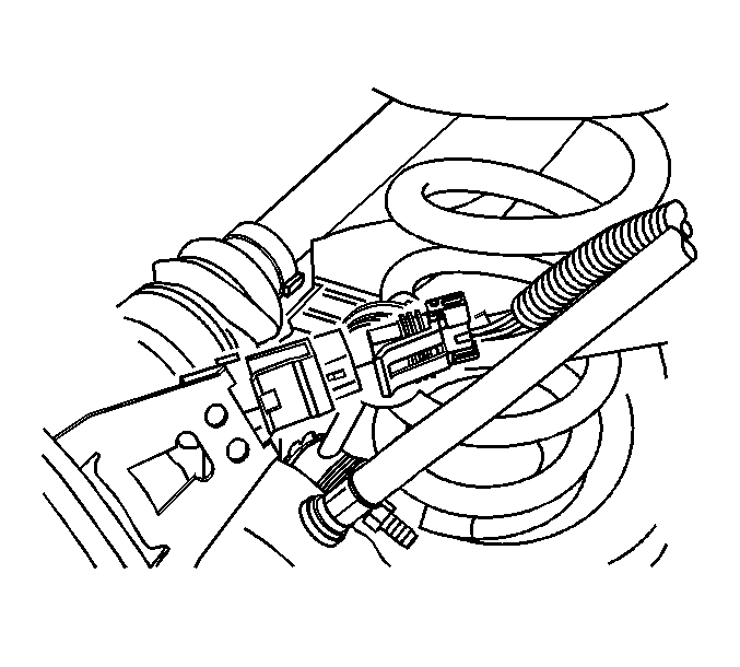
- Disconnect the antilock brake system (ABS) sensor harness connector.
- Disconnect the ABS sensor harness connector from the backing plate.
- Remove the parking brake cable bracket from the knuckle. Refer to Park Brake Cable Mounting Bracket Replacement.
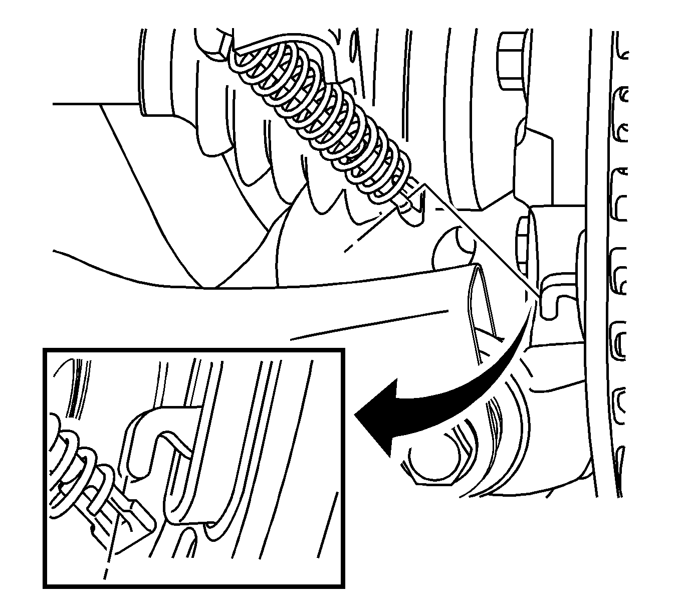
- Remove the parking brake cable from the parking brake lever (3).
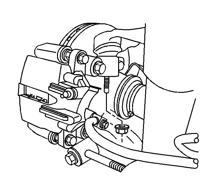
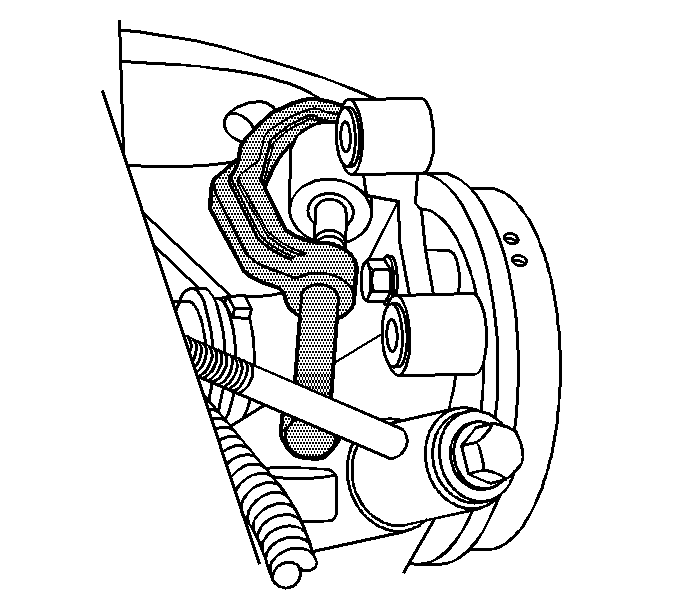
- Remove the upper ball joint mounting nut.
- Using J 43631 separate the ball stud from the knuckle.
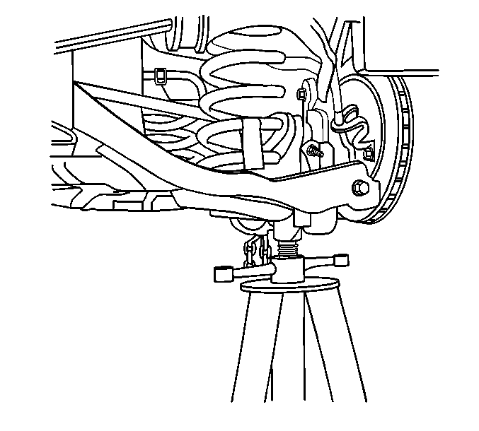
- Support the lower control arm with a suitable jack.
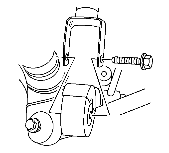
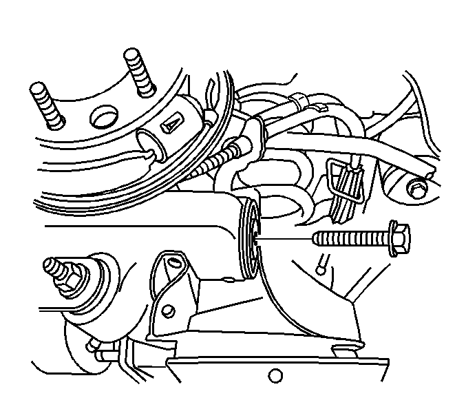
- Remove the lower dampener mounting bolt.
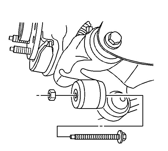
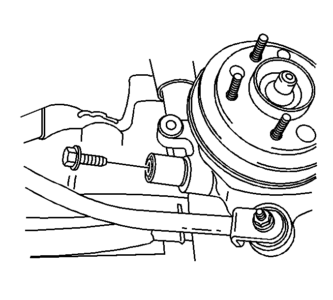
- Remove the trailing arm to knuckle mounting bolt and nut.
- Remove the lower control arm to knuckle mounting bolt.
- Remove the adjustment link to knuckle mounting bolt.
- Install J 45859 or equivalent to the wheel bearing/hub.
- Using the J 45859 or equivalent, disengage the wheel drive shaft from the wheel bearing/hub.
- Remove the knuckle from the vehicle.
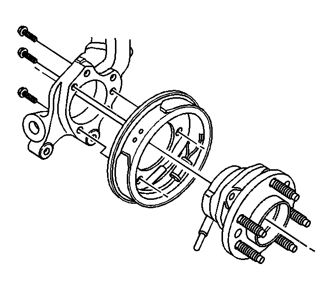
- Remove the wheel bearing/hub bolts.
- Remove the knuckle and backing plate from the wheel bearing/hub.
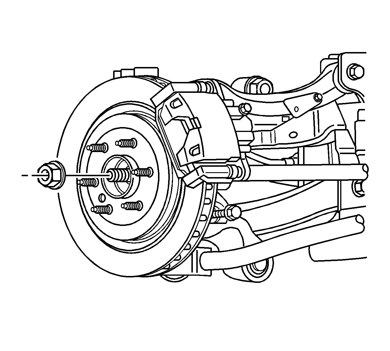
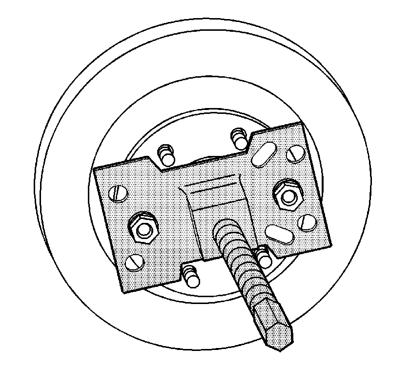
Note: May need to use the wheel hub remover to fully disengage the wheel bearing/hub from the drive axle.
Installation Procedure
- Install the knuckle and backing plate to the wheel bearing/hub.
- Install the wheel bearing/hub mounting bolts.
- Install the knuckle to the vehicle.
- Install the adjustment link to knuckle mounting bolt.
- Install the trailing arm to knuckle mounting bolt and nut.
- Install the lower dampener and mounting bolt.
- Install the lower control arm to knuckle mounting bolt.
- Connect the upper ball joint to the knuckle.
- Install the upper ball joint mounting nut.
- Install the parking brake cable bracket to the knuckle. Refer to Park Brake Cable Mounting Bracket Replacement.
- Remove the jack.
- Connect the ABS sensor electrical connector to the backing plate.
- Connect the ABS sensor electrical connector.
- Install a new wheel drive shaft nut.
- Install the brake rotor. Refer to Rear Brake Rotor Replacement.
- Install the tire and wheel. Refer to Tire and Wheel Removal and Installation.
- Lower the vehicle.

Caution: Refer to Fastener Caution in the Preface section.
Tighten
Tighten the bolts to 116 N·m (85 lb ft).

Note: Loosely install all fasteners before tightening.
Tighten
Tighten the adjustment link to knuckle bolt to 161 N·m (118 lb ft).

Tighten
Tighten the trailing arm to knuckle bolt to 172 N·m (127 lb ft).

Tighten
Tighten the lower shock mounting bolt to 150 N·m (111 lb ft).

Tighten
Tighten the lower control arm to knuckle retaining bolt to 161 N·m (118 lb ft).

Tighten
Tighten the nut to 66 N·m (48 lb ft).


Tighten
Tighten the nut to 160 N·m (118 lb ft).
