For 1990-2009 cars only
Special Tools
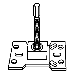
| • | J 45859 Wheel Hub Remover |
| • | J 43631 Ball Joint Remover |
Removal Procedure
- Raise and support the vehicle. Refer to Lifting and Jacking the Vehicle.
- Remove the tire and wheel. Refer to Tire and Wheel Removal and Installation.
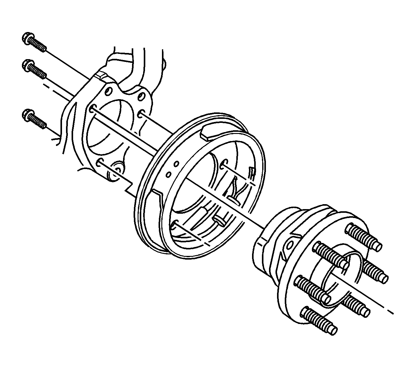
- Remove the rear brake rotor. Refer to Rear Brake Rotor Replacement.
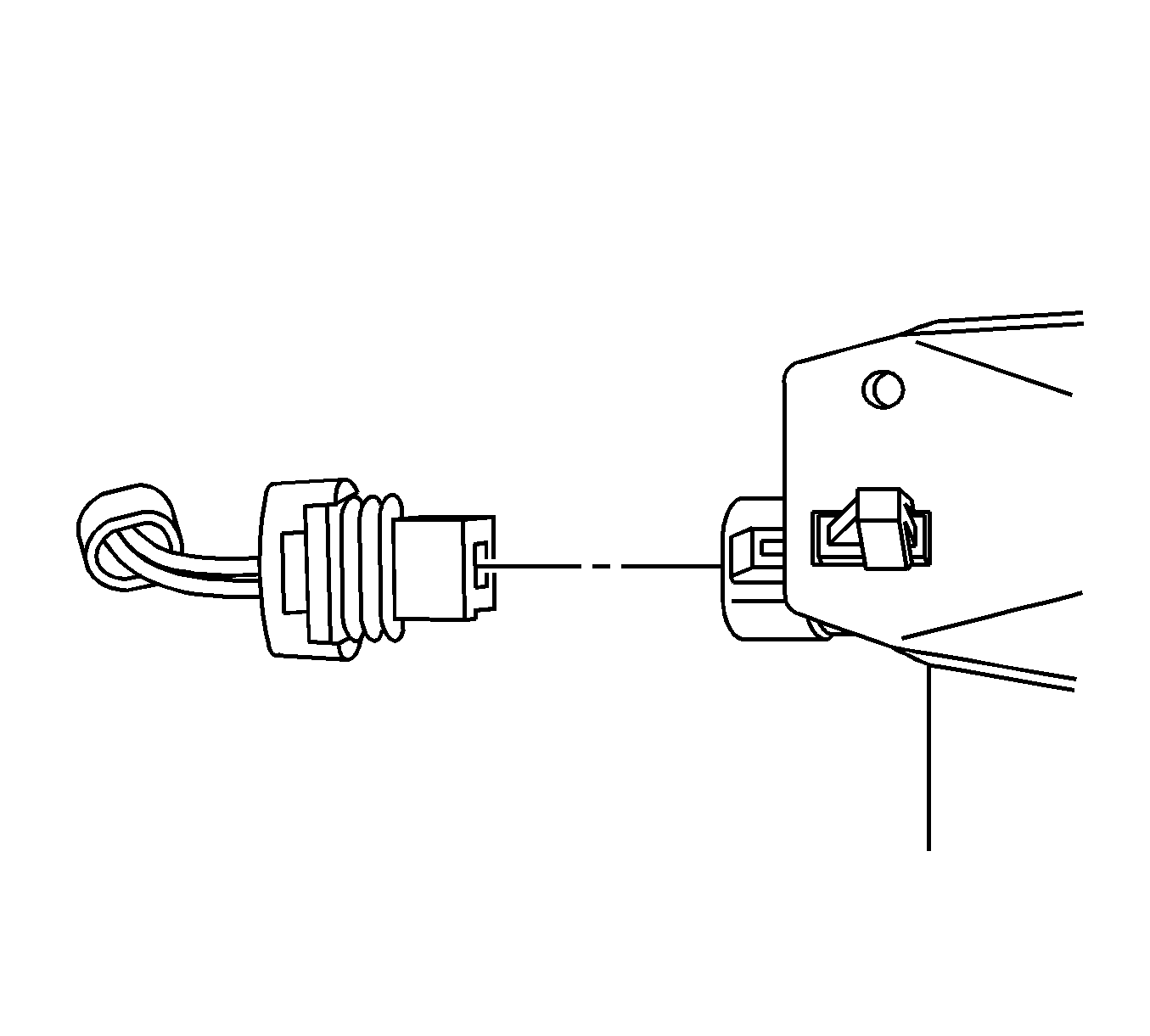
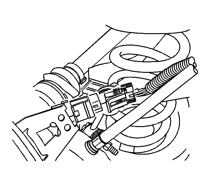
- Disconnect the wheel speed sensor electrical connector.
- Disconnect the wheel speed sensor electrical connector from the backing plate.
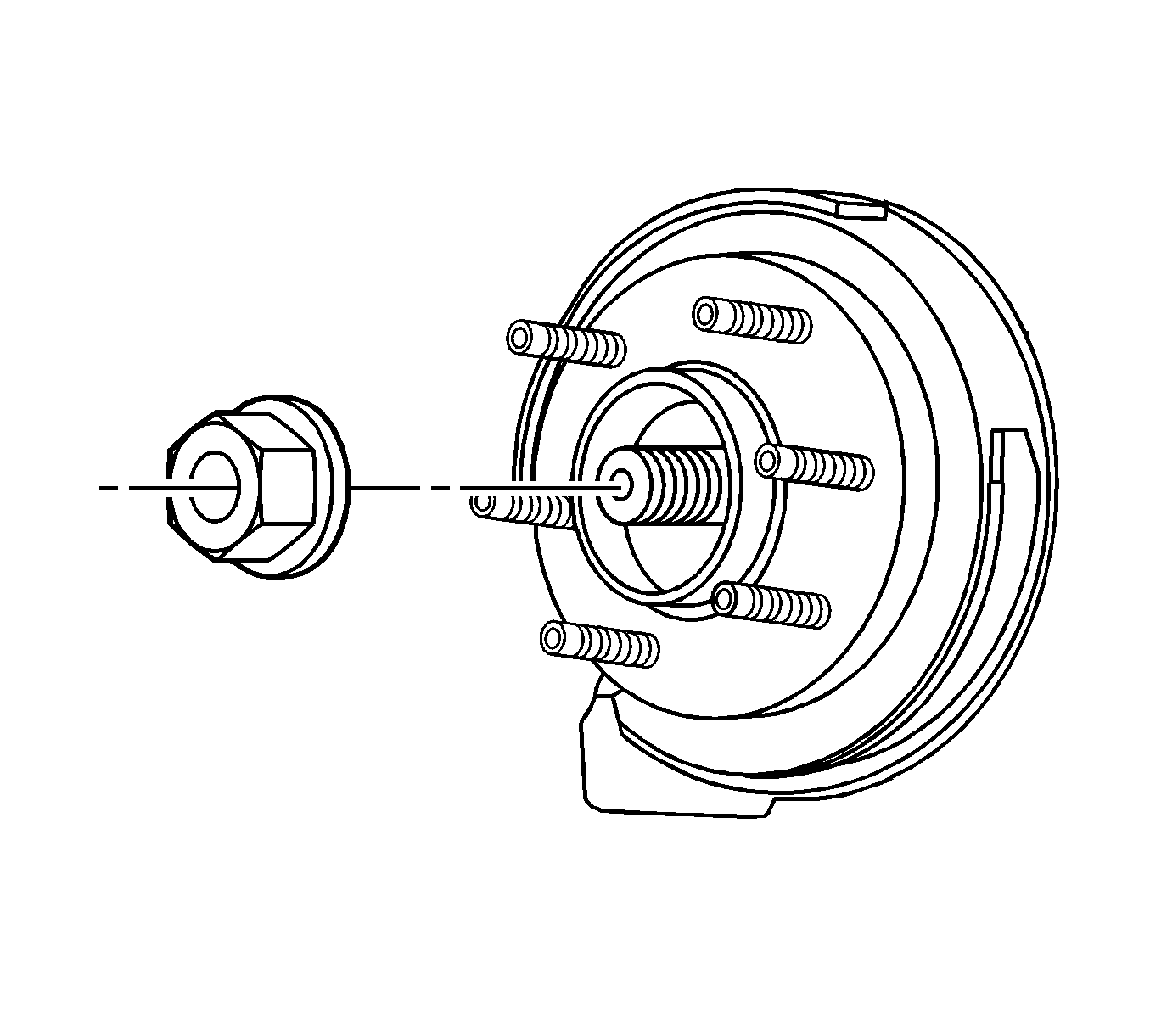
- Remove the wheel drive shaft retaining nut and discard.
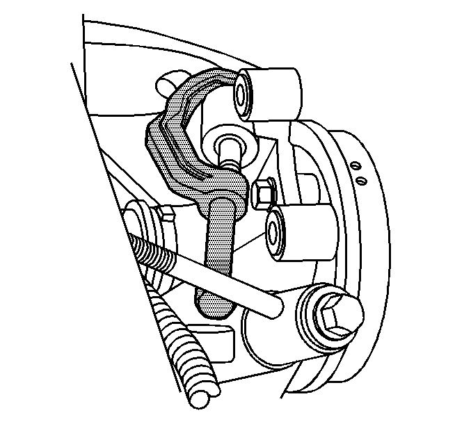
- Carefully remove the upper control arm to knuckle retaining nut.
- Using J 43631 carefully separate the upper control arm from the knuckle.
- Carefully remove the wheel bearing/hub retaining bolts.
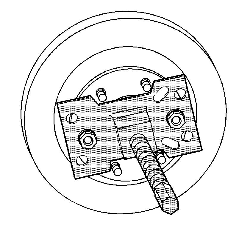
- Install J 45859 to the vehicle.
- Using J 45859 or equivalent to separate the wheel drive shaft from the wheel bearing/hub.
- Remove the wheel bearing/hub from the vehicle.
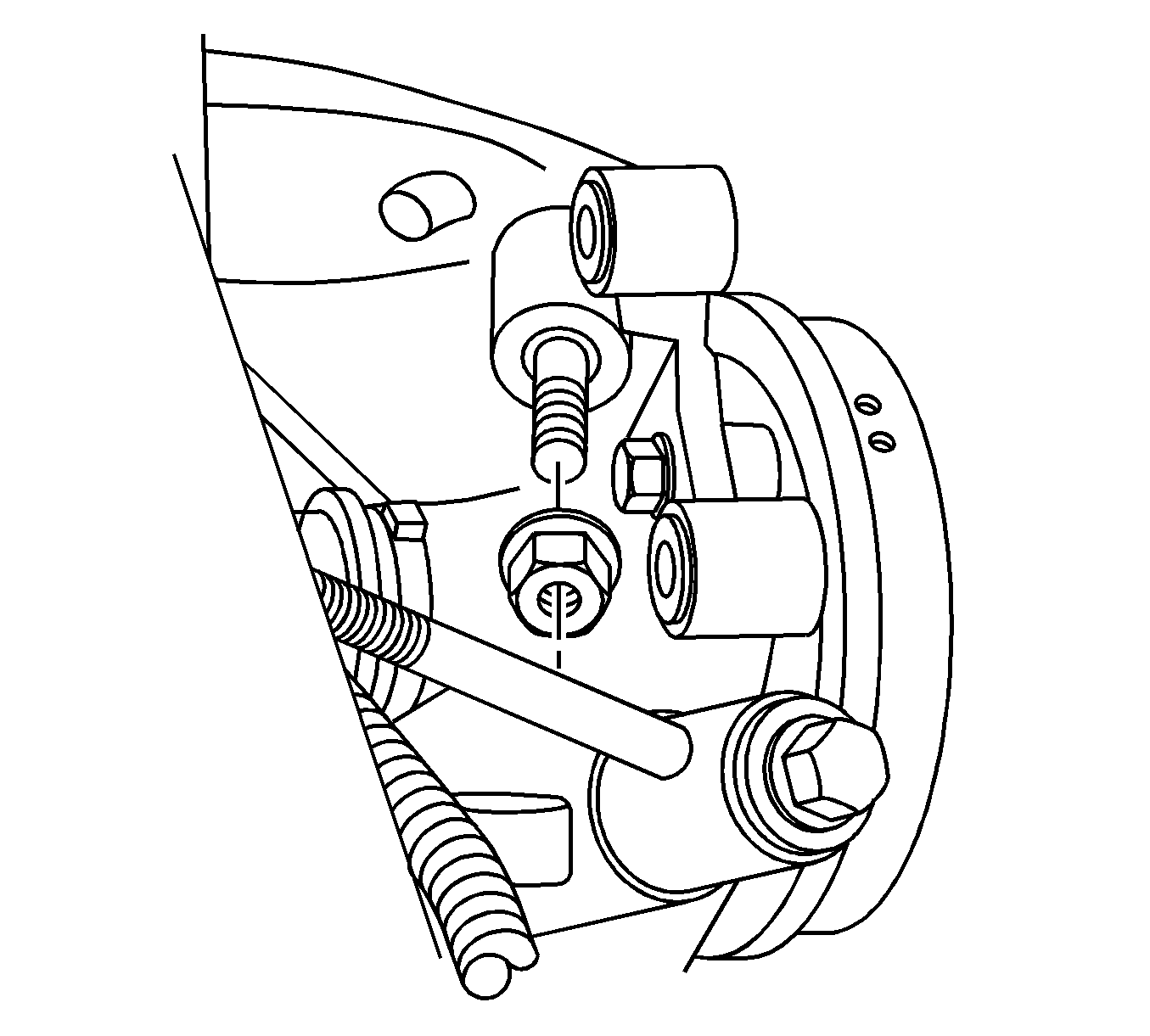
Caution: Avoid tool contact to the outer constant velocity boot when removing the wheel bearing mounting bolts. Failure to observe this caution may result in damage to the CV boot.
Installation Procedure
Caution: Refer to Fastener Caution in the Preface section.
Caution: Avoid tool contact to the outer constant velocity boot when removing the wheel bearing mounting bolts. Failure to observe this caution may result in damage to the CV boot.
- Install the wheel bearing/hub to the vehicle.
- Install the wheel bearing/hub retaining bolts.
- Install the upper control arm to the knuckle.
- Install the upper control arm to knuckle retaining nut.
- Install a new wheel drive shaft retaining nut.
- Install the brake rotor. Refer to Rear Brake Rotor Replacement.
- Connect the wheel speed sensor electrical connector to the backing plate.
- Connect the wheel speed sensor electrical connector.
- Install the tire and wheel. Refer to Tire and Wheel Removal and Installation.
- Lower the vehicle.
Tighten
Tighten the bolts to 125 N·m (92 lb ft).
Tighten
Tighten the upper ball joint nut to 66 N·m (48 lb ft).
Tighten
Tighten the nuts to 160 N·m (118 lb ft).