Battery Negative Cable Disconnection and Connection LHD
Removal Procedure
Caution: Refer to Battery Disconnect Caution in the Preface section.

- Turn OFF all the lamps and accessories.
- Turn the ignition OFF.
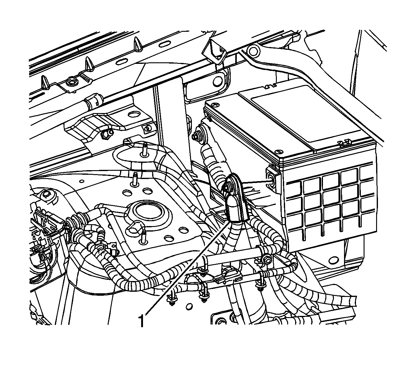
- Remove the negative battery cable cover, if necessary.
- Loosen the negative battery cable bolt.
- Remove the negative battery cable (1) from the battery.
Installation Procedure

Important: Clean any existing corrosion from the battery terminal , the battery cable bolt, and the battery cable.
- Position the negative battery cable (1) to the battery.
Notice: Refer to Fastener Notice in the Preface section.
- Tighten the negative battery cable bolt.
Tighten
Tighten the bolt to 17 N·m (13 lb ft).
- Install the negative battery cable cover, if necessary.
- Perform the power sunroof calibration, if required:
| 4.1. | Turn the ignition switch to the RUN position. |
| 4.2. | Turn the power sunroof switch to the closed position. After the sunroof fully closes and the motor stops, press and hold in the switch for 3 seconds. |
| 4.3. | Turn the power sunroof switch to the tilt position. After the sunroof reaches the tilt position and the motor stops, press and hold in the switch for 3 seconds. |
| 4.4. | Turn the power sunroof switch to the full open position. After the sunroof is fully open and the motor stops, press and hold in the switch for 3 seconds. |
| 4.5. | Turn the power sunroof switch to the closed position. After the sunroof fully closes and the motor stops, press and hold in the switch for 3 seconds. |
- Perform the power windows calibration:
| 5.1. | Repeat these steps for each window. |
| 5.2. | Turn the ignition switch to the RUN position. |
| 5.3. | Press the power window switch to the down position. After the window is in the full down position, press and hold the switch in the down position for 3 seconds. |
| 5.4. | Press the power window switch to the up position. After the window is in the full up position, press and hold the switch in the up position for 3 seconds. |
- Perform the heat and A/C control head calibration:
| 6.1. | Turn the ignition switch to the RUN position. |
| 6.2. | Simultaneously press the AUTO and OFF buttons, located on the heat and A/C control head, for at least 5 seconds. |
| 6.3. | After initiation, the stepper motors will cycle from one stop to the other. You may hear the motors cycling while calibrating. |
- Relearn the tire pressure sensor system, if necessary. Refer to
Tire Pressure Sensor Learn
.
Battery Negative Cable Disconnection and Connection RHD
Removal Procedure
Caution: Refer to Battery Disconnect Caution in the Preface section.

- Turn OFF all the lamps and accessories.
- Turn the ignition OFF.
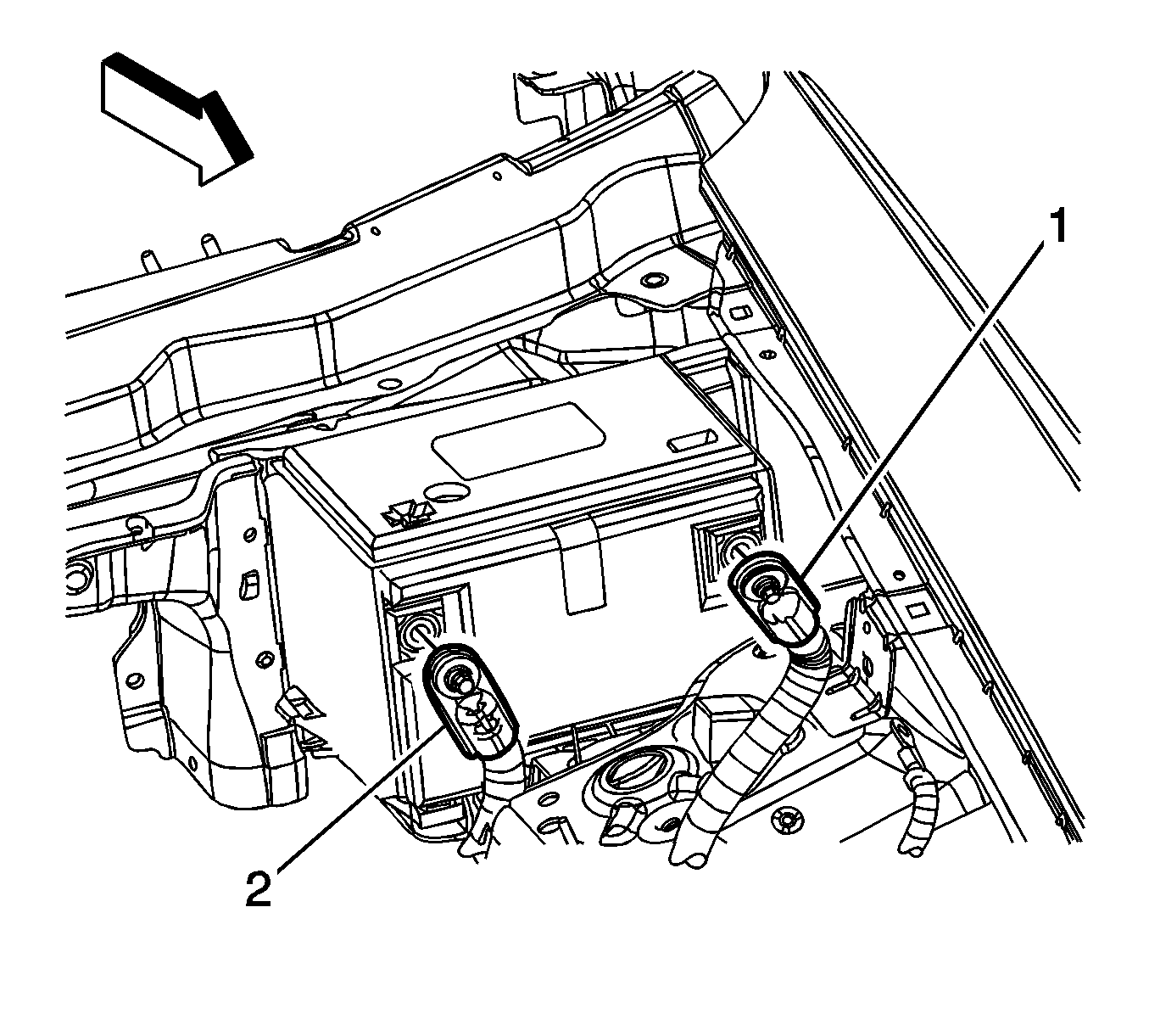
- Remove the negative battery cable cover, if necessary.
- Loosen the negative battery cable bolt.
- Remove the negative battery cable (1) from the battery.
Installation Procedure

Important: Clean any existing corrosion from the battery terminal , the battery cable bolt, and the battery cable.
- Position the negative battery cable (1) to the battery.
Notice: Refer to Fastener Notice in the Preface section.
- Tighten the negative battery cable bolt.
Tighten
Tighten the bolt to 17 N·m (13 lb ft).
- Install the negative battery cable cover, if necessary.
- Perform the power sunroof calibration, if required:
| 4.1. | Turn the ignition switch to the RUN position. |
| 4.2. | Turn the power sunroof switch to the closed position. After the sunroof fully closes and the motor stops, press and hold in the switch for 3 seconds. |
| 4.3. | Turn the power sunroof switch to the tilt position. After the sunroof reaches the tilt position and the motor stops, press and hold in the switch for 3 seconds. |
| 4.4. | Turn the power sunroof switch to the full open position. After the sunroof is fully open and the motor stops, press and hold in the switch for 3 seconds. |
| 4.5. | Turn the power sunroof switch to the closed position. After the sunroof fully closes and the motor stops, press and hold in the switch for 3 seconds. |
- Perform the power windows calibration:
| 5.1. | Repeat these steps for each window. |
| 5.2. | Turn the ignition switch to the RUN position. |
| 5.3. | Press the power window switch to the down position. After the window is in the full down position, press and hold the switch in the down position for 3 seconds. |
| 5.4. | Press the power window switch to the up position. After the window is in the full up position, press and hold the switch in the up position for 3 seconds. |
- Perform the heat and A/C control head calibration:
| 6.1. | Turn the ignition switch to the RUN position. |
| 6.2. | Simultaneously press the AUTO and OFF buttons, located on the heat and A/C control head, for at least 5 seconds. |
| 6.3. | After initiation, the stepper motors will cycle from one stop to the other. You may hear the motors cycling while calibrating. |
- Relearn the tire pressure sensor system, if necessary. Refer to
Tire Pressure Sensor Learn
.
Battery Negative Cable Disconnection and Connection LHD Top Post
Removal Procedure
Caution: When performing service on or near the SIR components or the SIR wiring, the SIR system must be disabled. Refer to SIR Disabling and Enabling .
Failure to observe the correct procedure could cause deployment of the SIR components, personal injury, or unnecessary SIR system repairs.
Caution: Refer to Battery Disconnect Caution in the Preface section.
- Turn OFF all the lamps and accessories.
- Turn the ignition OFF.
- Make sure the ignition switch is in the OFF position.

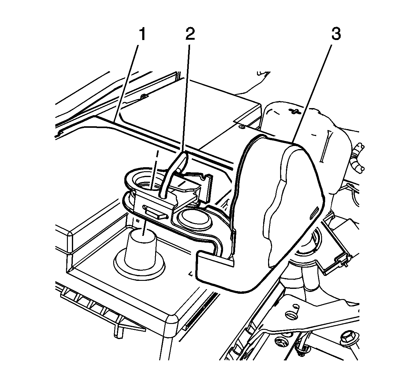
- Rotate the cover (3) in order release the clamp locking lever (2).
- Remove the clamp from the battery (1)
Connect Procedure

- Connect the battery negative cable clamp to the battery (1).
- Rotate the clamp locking lever (2) into the locking position.
- Position the cover (3) over the clamp.
- Power sunroof calibration:
| 4.1. | Turn the ignition switch to the RUN position. |
| 4.2. | Turn the power sunroof switch to the closed position. After the sunroof fully closes and the motor stops, press and hold in the switch for 3 seconds. |
| 4.3. | Turn the power sunroof switch to the tilt position. After the sunroof reaches the tilt position and the motor stops, press and hold in the switch for 3 seconds. |
| 4.4. | Turn the power sunroof switch to the full open position. After the sunroof is fully open and the motor stops, press and hold in the switch for 3 seconds. |
| 4.5. | Turn the power sunroof switch to the closed position. After the sunroof fully closes and the motor stops, press and hold in the switch for 3 seconds. |
- Power windows calibration:
| 5.1. | Repeat these steps for each window. |
| 5.2. | Turn the ignition switch to the RUN position. |
| 5.3. | Press the power window switch to the down position. After the window is in the full down position, press and hold the switch in the down position for 3 seconds. |
| 5.4. | Press the power window switch to the up position. After the window is in the full up position, press and hold the switch in the up position for 3 seconds. |
- Heat and A/C control head calibration:
| 6.1. | Turn the ignition switch to the RUN position. |
| 6.2. | Simultaneously press the AUTO and OFF buttons, located on the heat and A/C control head, for at least 5 seconds. |
| 6.3. | After initiation, the stepper motors will cycle from one stop to the other. You may hear the motors cycling while calibrating. |
- Relearn the tire pressure sensor system, if necessary. Refer to
Tire Pressure Sensor Learn
.


