For 1990-2009 cars only
Tools Required
J 45059 Angle Meter
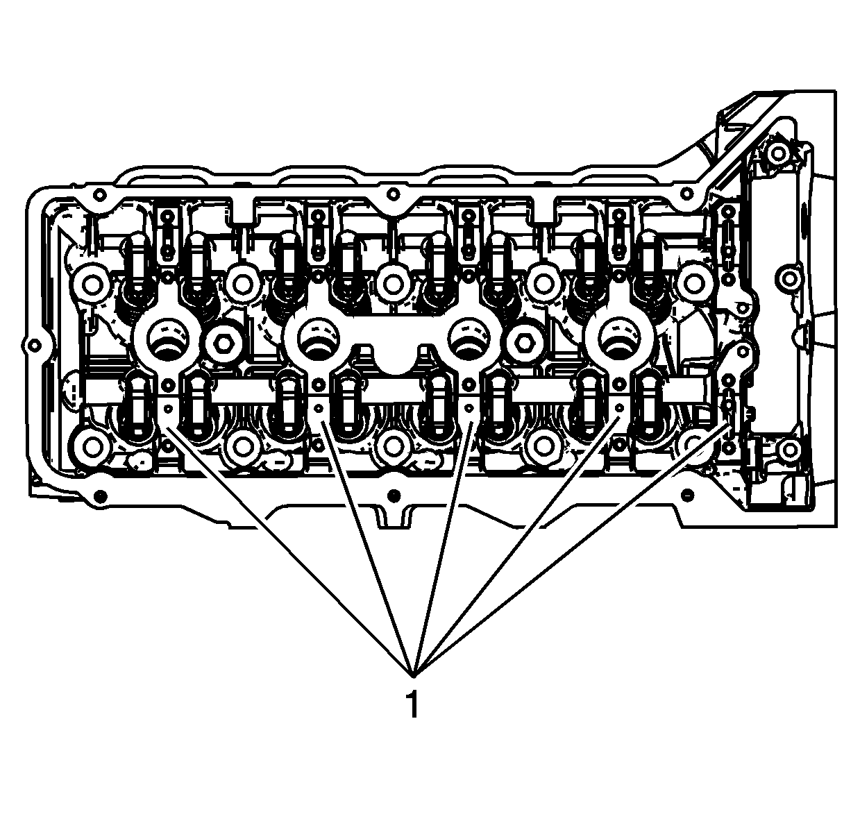
- Clean the camshaft journals, camshaft and the camshaft caps with a clean, lint-free cloth.
- Apply a liberal amount of lubricant GM P/N 12345001 or equivalent to the camshaft bearing journals (1).
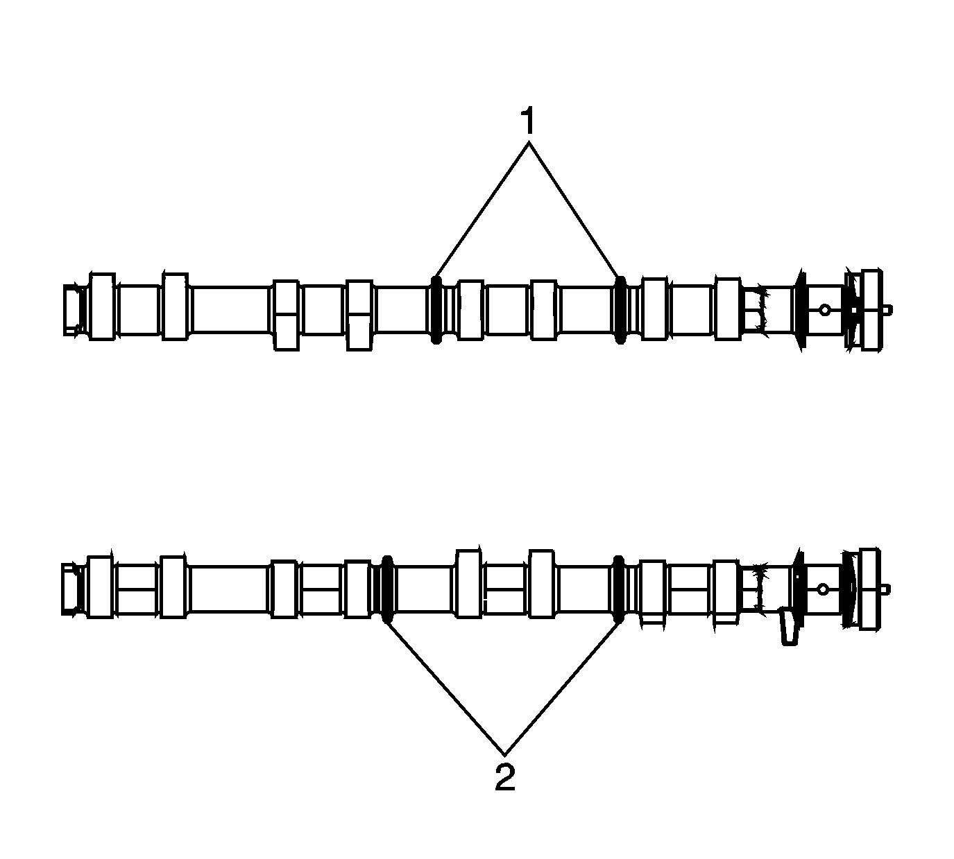
- Select the proper camshaft by the identifying rings cast into the right exhaust camshaft (2).
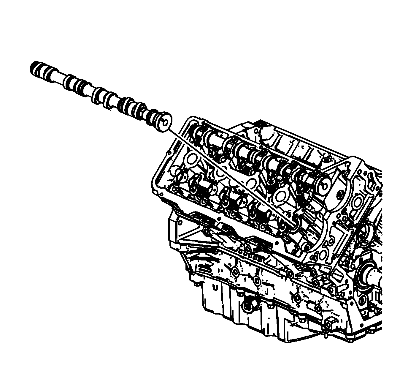
- Apply a liberal amount of lubricant GM P/N 12345001 or equivalent to the camshaft lobes and the camshaft journals.
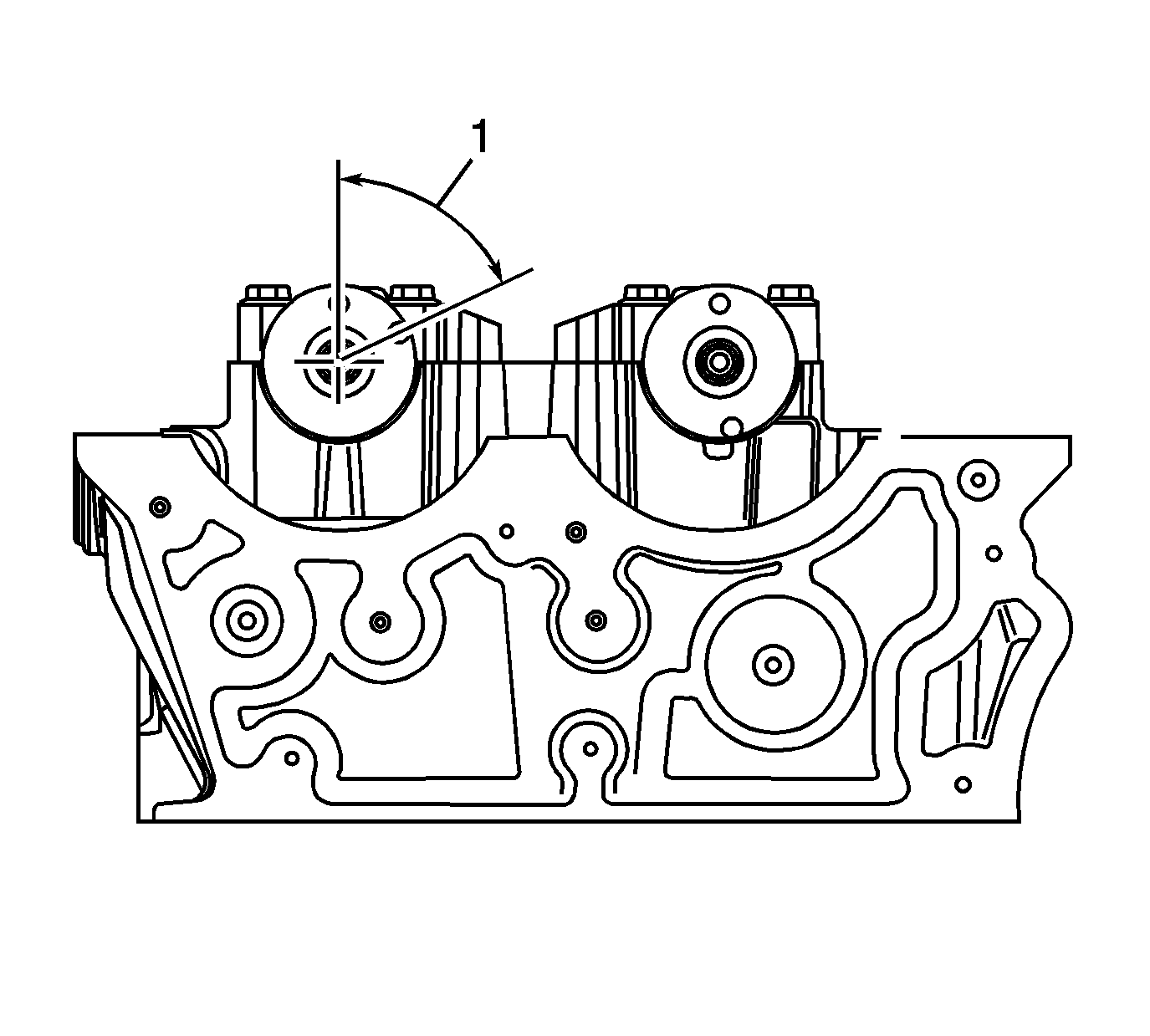
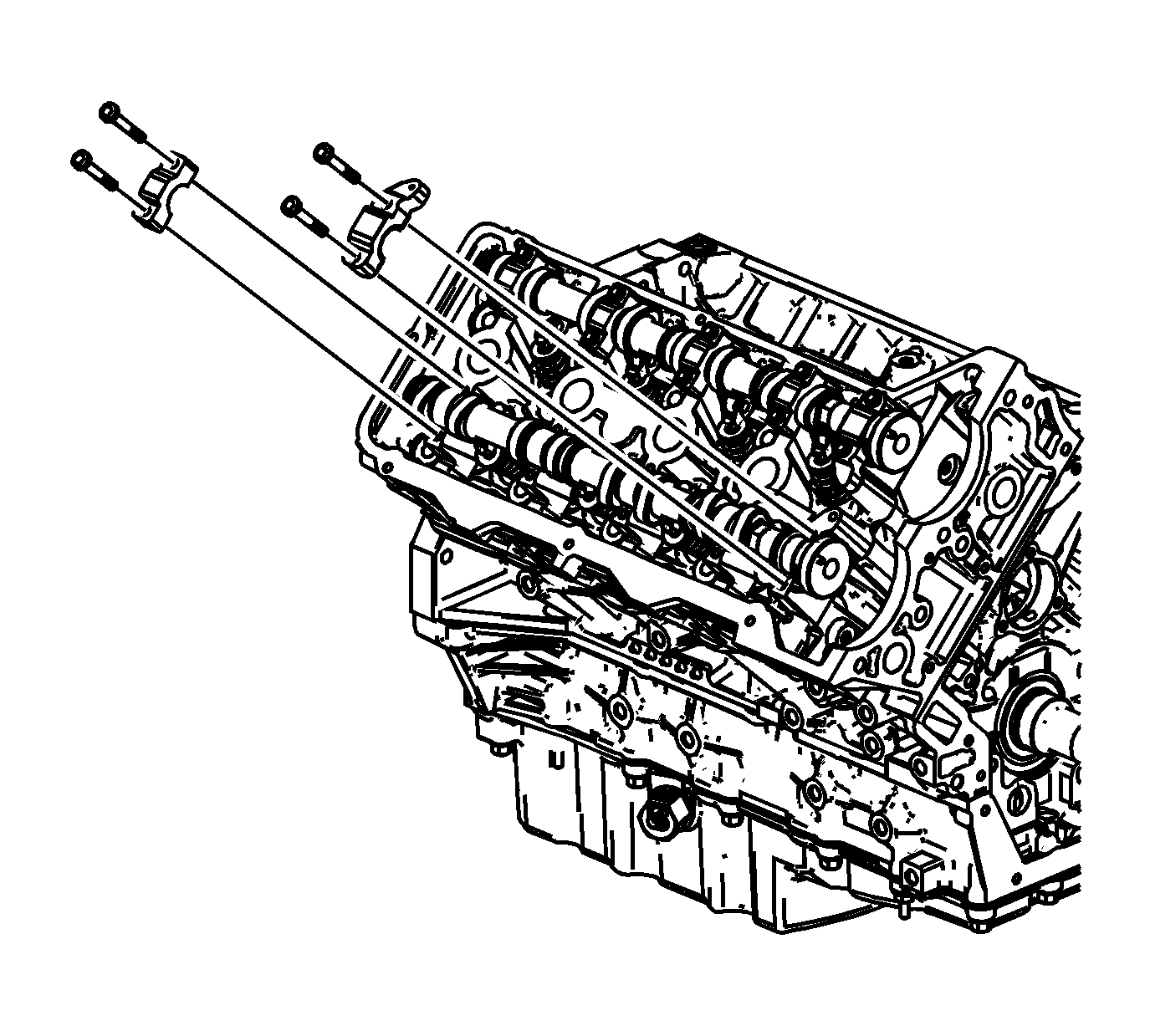
- Place the camshaft in the camshaft journals with the camshaft sprocket drive pins near the 45 to 60 degree location (1), clockwise from the top of their rotation and the camshaft lobes in a neutral position. The camshaft can be identified by a stamping near the rear journal. For example: R-EXH is defined as Right Bank Exhaust.
- Observe the markings on the camshaft bearing caps. Each camshaft bearing cap is marked in order to identify its location. The markings have the following meanings:
- Apply a liberal amount of lubricant GM P/N 12345001 or equivalent to the right exhaust camshaft bearing cap journals.
- Install the right exhaust camshaft bearing caps according to the identifications marks.
- Hand start all the right exhaust camshaft bearing cap bolts.
- Install the right cylinder head exhaust camshaft bearing cap bolts.
Important: Ensure each valve rocker arm is properly aligned to the valve tip, the valve lifter and the camshaft lobe. Inspect the alignment prior to and after the camshaft caps are tightened to specifications.
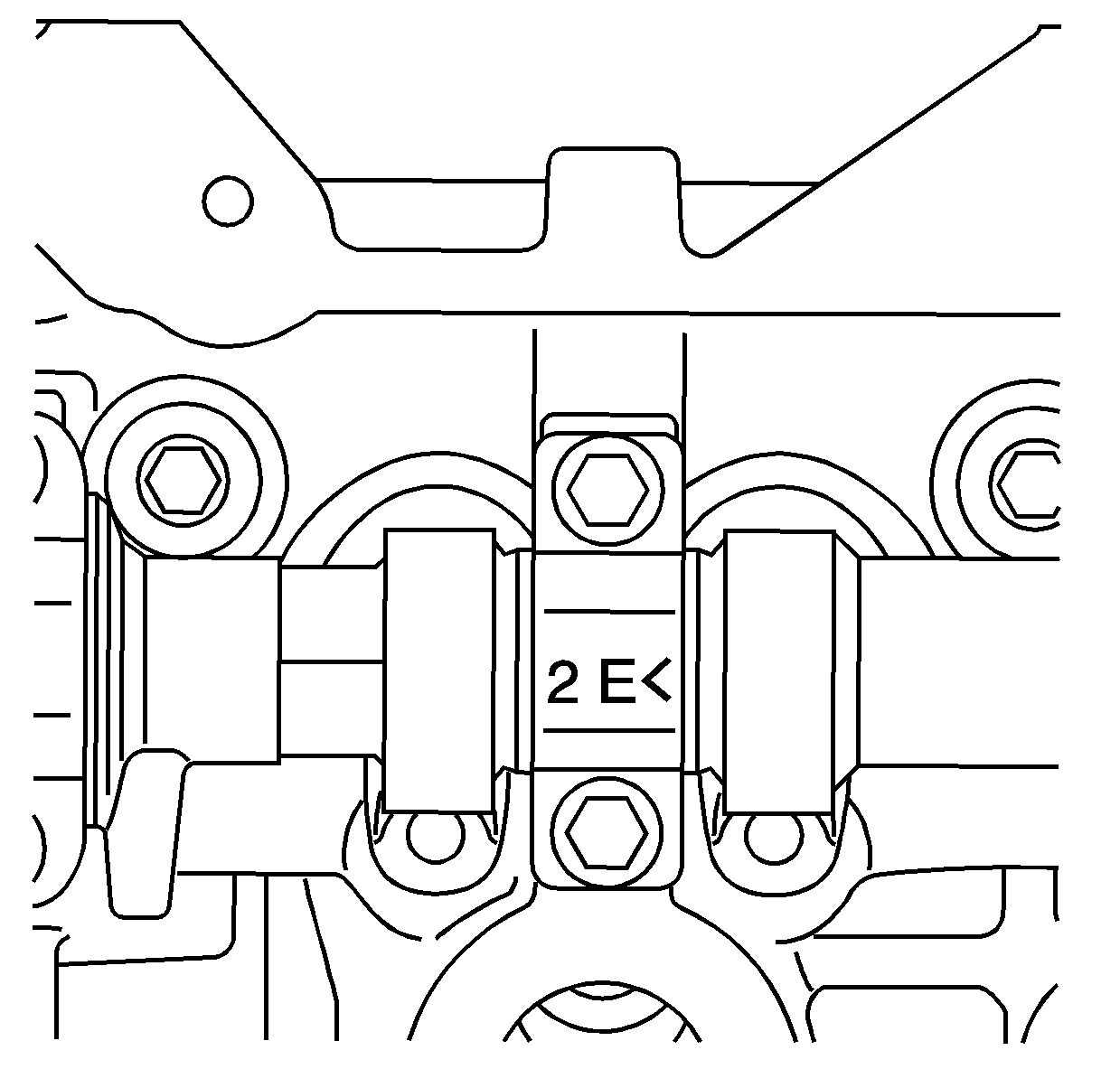
| • | The arrow should point toward the front of the engine. |
| • | The number indicates the position from the front of the engine. |
| • | The "E" indicates the exhaust camshaft. |
Notice: Refer to Fastener Notice in the Preface section.
Important: Ensure each valve rocker arm is properly aligned to the valve tip, the valve lifter and the camshaft lobe. Inspect the alignment prior to and after the camshaft caps are tightened to specifications.
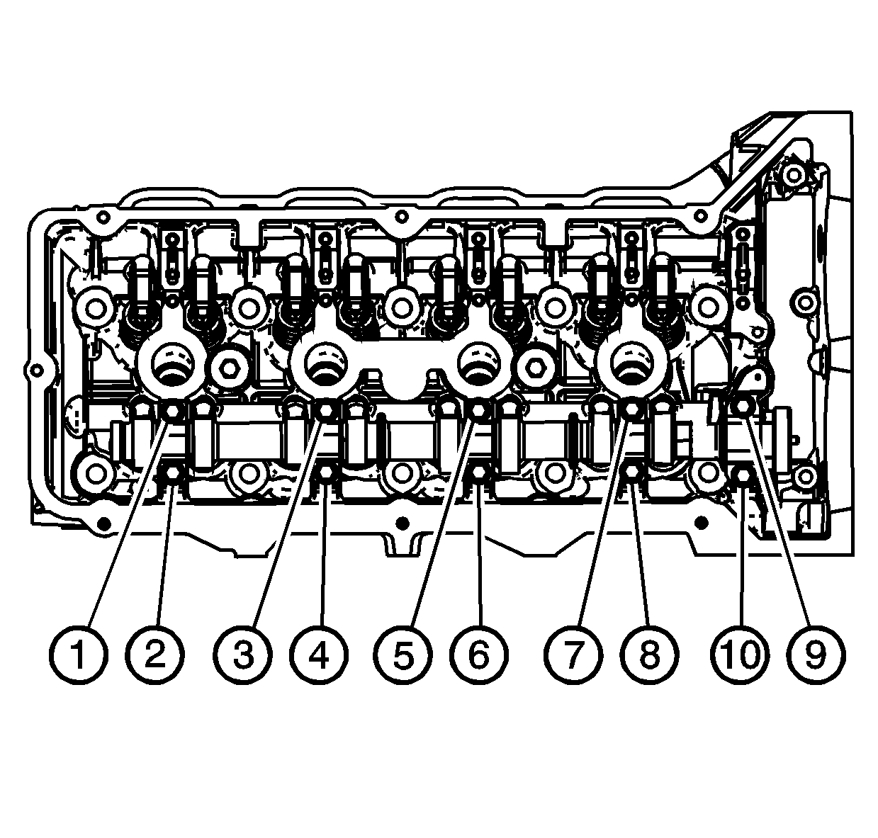
| 10.1. | First Pass |
Tighten
Tighten the camshaft bearing cap bolts to 5 N·m (44 lb in).
| 10.2. | Final Pass |
Tighten
Tighten the camshaft bearing cap bolts an additional 30 degrees using the
J 45059
.
