For 1990-2009 cars only
Removal Procedure
- Disable the SIR system. Refer to SIR Disabling and Enabling .
- Disconnect the adjuster pedal switch connector at the base of the steering column.
- Remove the wire harness straps from the wire harness assembly.
- Remove the adjuster pedal switch lead from the wire harness assembly.
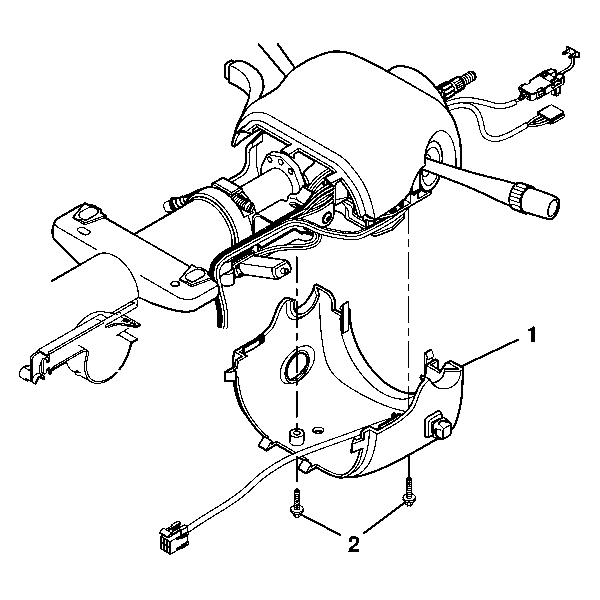
- Remove the 2 pan head tapping screws (2) from the lower trim cover (1).
- Remove the lower trim cover (2).
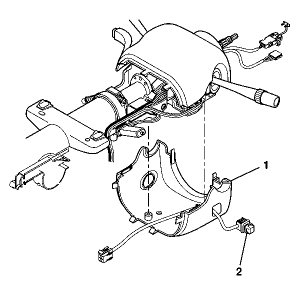
- Remove the adjuster pedal switch assembly (2) from the lower trim cover (1).
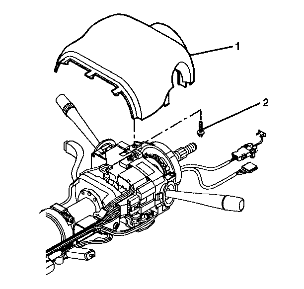
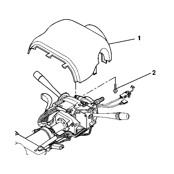
- Remove the TORX® head screw (2) from the upper trim cover (1).
- Remove the upper trim cover (1).
Caution: Refer to SIR Caution in the Preface section.


Installation Procedure
- Install the upper trim cover (1) and secure by using the TORX® head screw (2).
- Install the adjuster pedal switch assembly (2) into the lower trim cover (1).
- Install the lower trim cover (1).
- Install the 2 pan head tapping screws (2) into the lower trim cover (1).
- Route the adjuster pedal switch lead into the wire harness assembly.
- Install the wire harness straps onto the wire harness assembly.
- Connect the adjuster pedal switch connector at the base of the steering column.
- Enable the SIR system. Refer to SIR Disabling and Enabling .
Notice: Refer to Fastener Notice in the Preface section.

Tighten
Tighten the screws to 1.5 N·m (13 lb in).


Tighten
Tighten the screws to 3.5 N·m (31 lb in).
