For 1990-2009 cars only
Tools Required
| • | J 25070 Heat Gun |
| • | J 42168-9 Holding Strap |
| • | J 45013-2 Gage Assembly |
| • | J 45013-3 Gage Cylinder |
| • | J 45013-5 Gage Centering Assembly |
| • | J 45013-7 Adapter Screw |
| • | J 45019 Flange and Pinion Cage Remover |
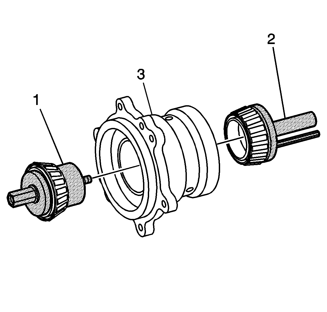
- Install pinion tail bearing then the pinion bearing spacer on the J 45013-5 (1).
- Install the head bearing on J 45013-2 (2).
- Install them into the pinion bearing cage (3) as shown.
- Snug the J 45013-7 . This will apply the proper bearing preload determined by the custom ground spacer that is provided with the bearing kit.
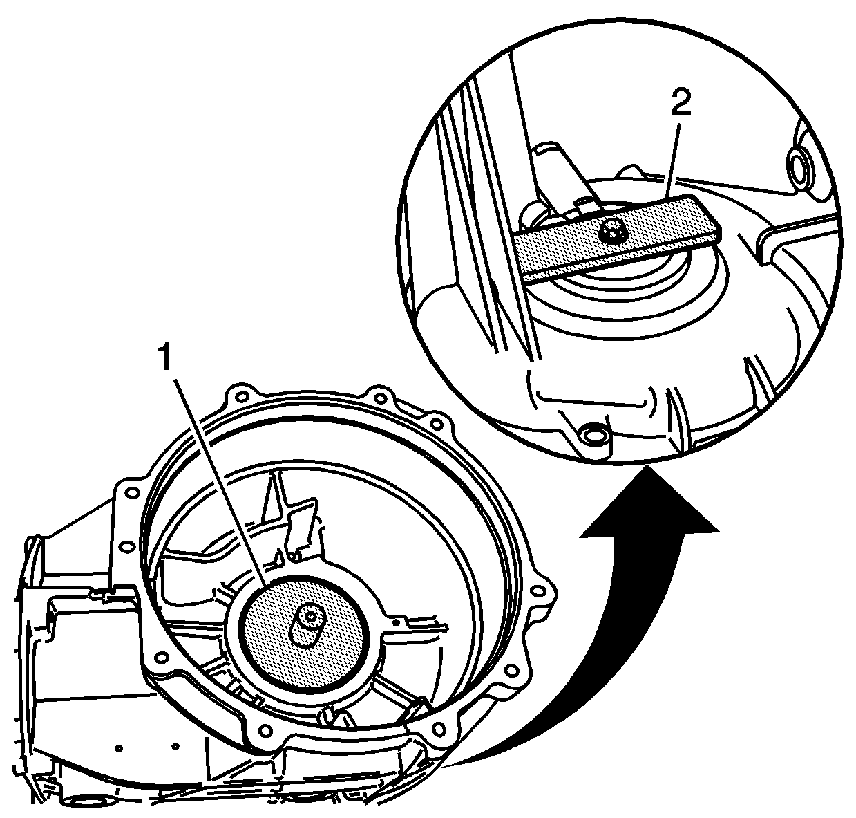
- Install the J 45013-3 (1) into the differential carrier as shown.
- Turn the carrier over and attach the holding strap J 42168-9 and thumb screw (2). Snug the thumb screw.
- Inspect the pinion cage surfaces. Ensure that there are no nicks or burrs on the pinion cage surfaces or in the carrier bore.
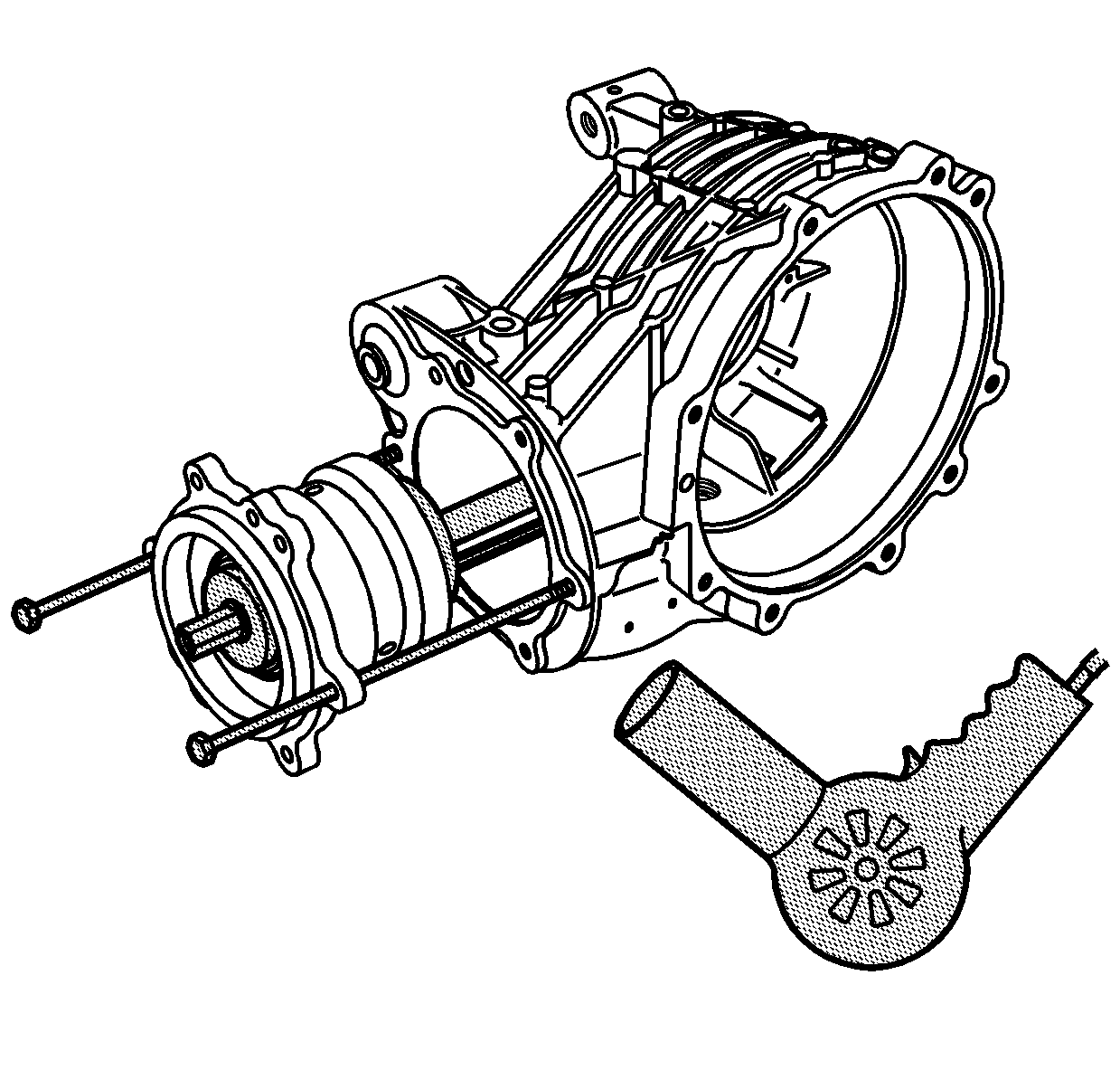
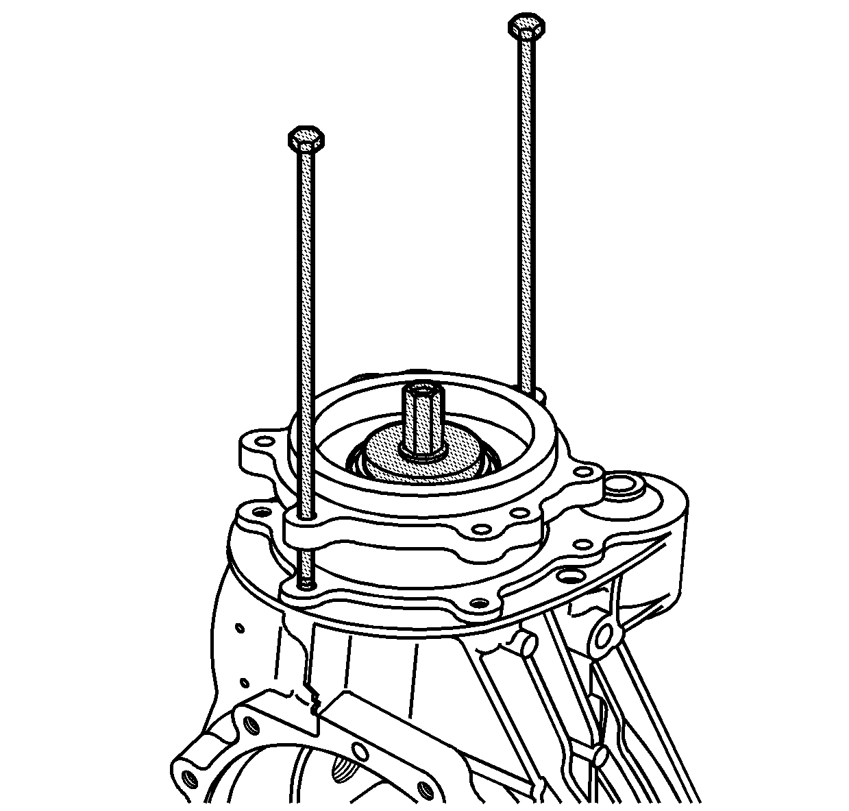
- Using 2 long bolts from J 45019 as guides, align the bolt holes of the pinion cage and the carrier. Snug the bolts.
- Apply a light coat of gear lube to the carrier bore and pinion cage in order to ease assembly.
- Heat the carrier using J 25070 in order to ease pinion cage assembly.
- While aligning the guide bolts and bolt holes, push the pinion cage into the bore of the carrier.
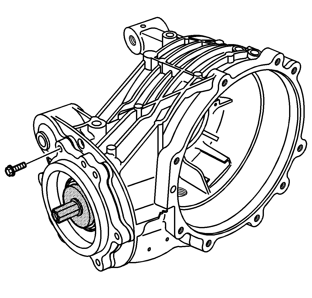
- Install the pinion cage bolts and tighten in a criss-cross pattern.
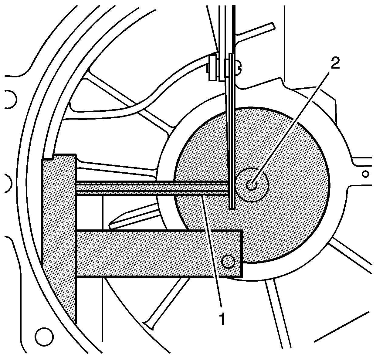
- Measure the distance between the hex rod on the J 45013-2 (1) and the post on the J 45013-3 (2). Record this measurement.
- Subtract this measurement from 5 mm (0.196 in). This is the amount of pinion shim size value B2.
- Remove J 45013-3 from the carrier.
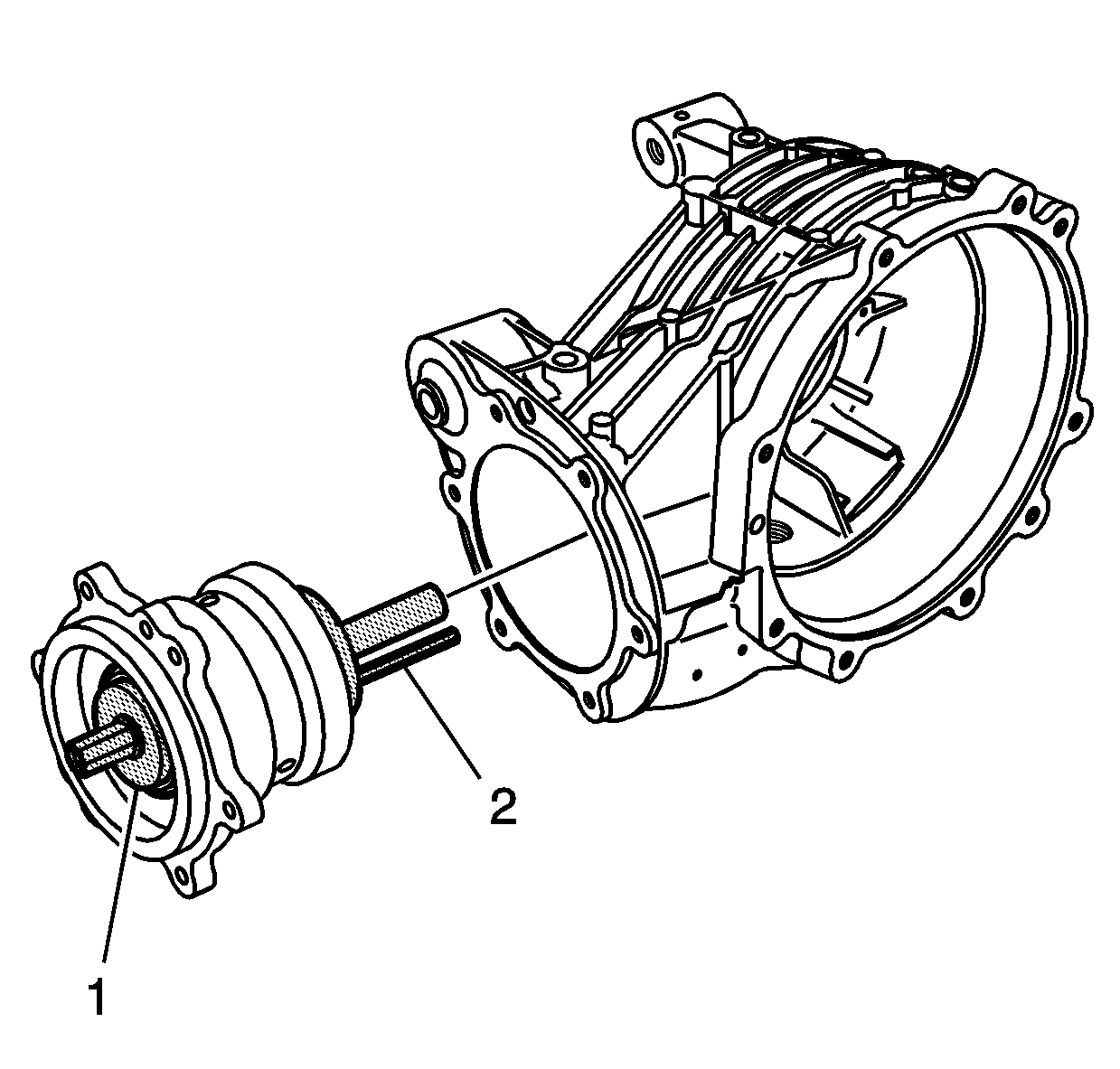
Important: When installing the pinion bearing housing into the carrier, ensure that the gage rod (2) does not hit the ribbing inside the carrier.
Notice: Refer to Fastener Notice in the Preface section.
Tighten
Tighten the pinion cage bolts to 29 N·m (21 lb ft).
