Special Tools
| • |
J 42572
Drive Shaft Seal Clamp Pliers |
Removal Procedure
This procedure is to be performed only after the wheel drive shaft has been removed from the vehicle. Refer to
Rear Wheel Drive Shaft Replacement.
- Remove the bolt and washer assemblies from the wheel drive shaft.
- Wrap a shop towel around the wheel drive shaft.
- Place the wheel drive shaft horizontally in a vise.
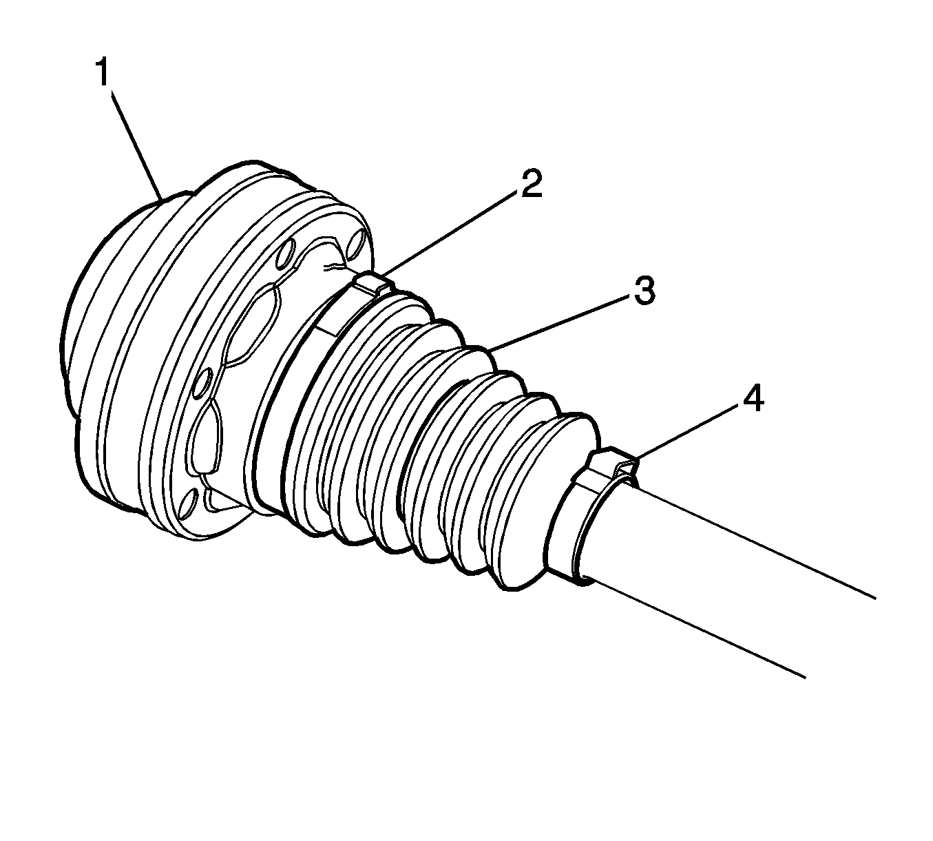
- Using a side cutter or other suitable tool, remove the large boot clamps (2) and (4) from the inner joint boot (3).
- Remove the boot (3) from the joint (1) by moving the boot toward the outer joint.
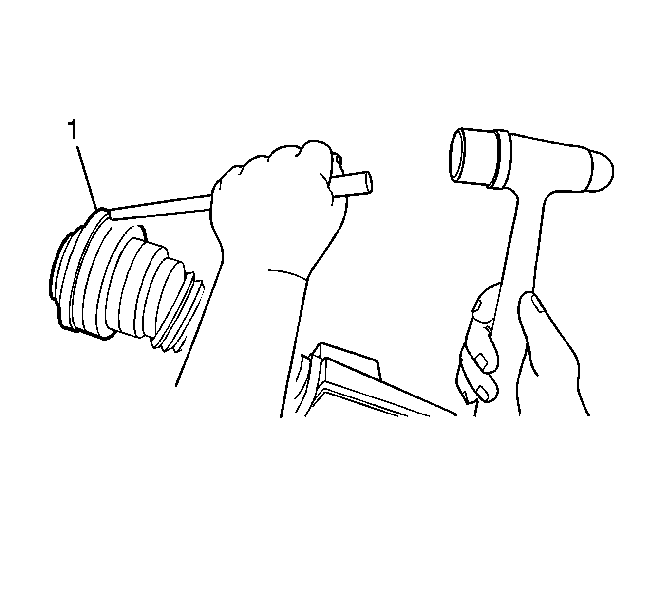
- Using a hammer and a punch, remove and discard the grease cover (1) from the joint.
- Remove the grease from the face of the joint inner race, cage, balls, etc.
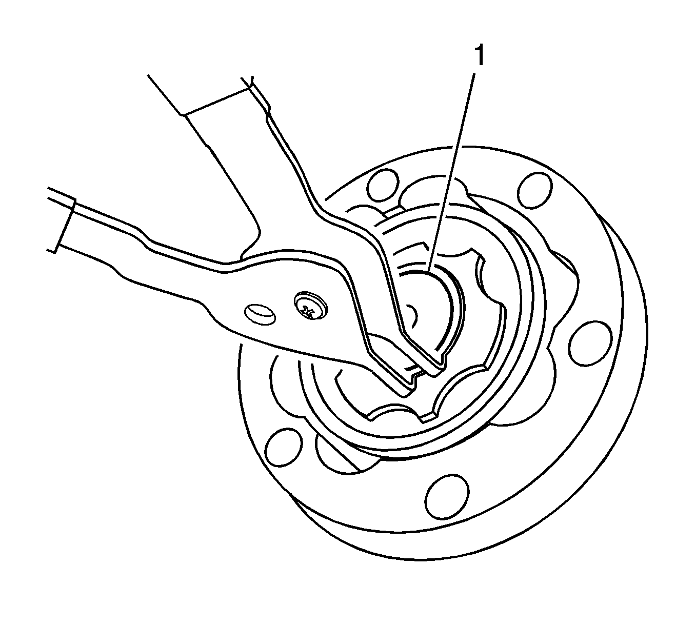
- Using snap ring pliers, remove the joint race retaining ring (1).
- Hold the inner joint horizontally to the wheel drive shaft.
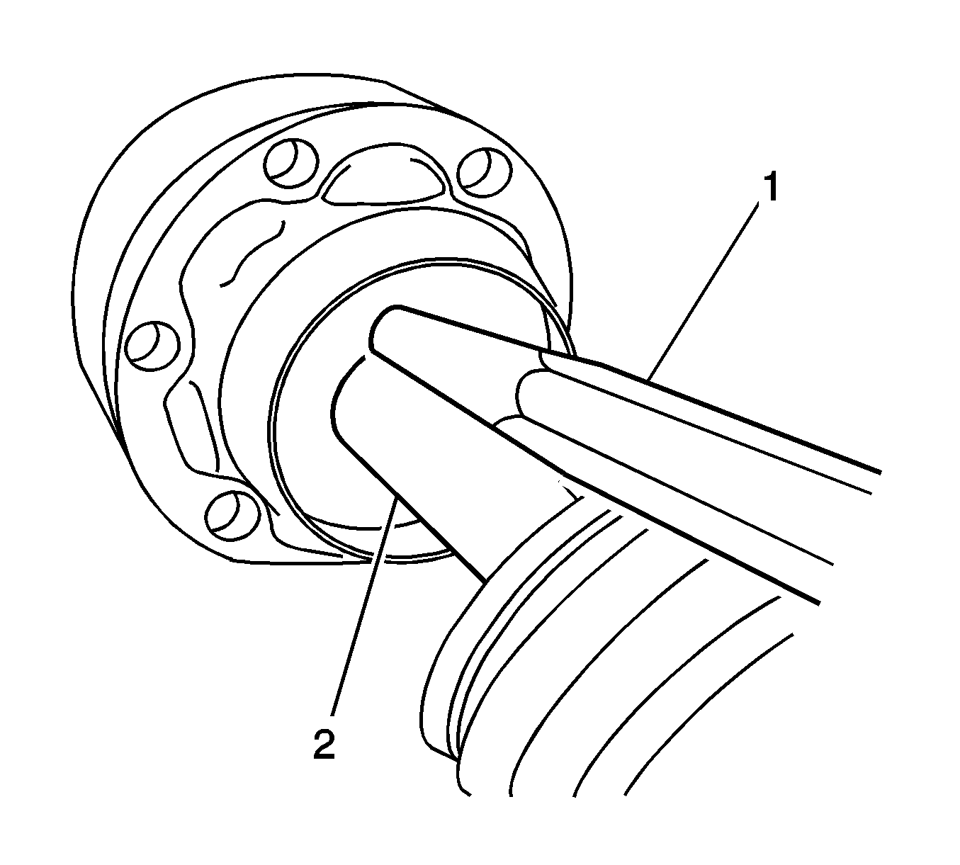
- Position the brass drift (1) on the inner race (2).
- Carefully strike the brass drift (1) with a hammer to remove the inner joint assembly (2) from the wheel drive shaft.
- Remove the boot from the wheel drive shaft.
Important: All traces of the old grease and any contaminates must be removed.
- Clean the following parts thoroughly with clean solvent:
| • | The wheel drive shaft exposed end |
- Thoroughly air dry all of the parts.
- Inspect the following parts for damage and/or wear:
| • | The wheel drive shaft exposed end |
Installation Procedure
- Insert approximately 60 percent of the grease from the service kit into the inner joint.
| 1.1. | Spread 60 percent the grease onto the ball tracks, the balls, the cage, and the inner race. |
| 1.2. | Spread the remainder of the grease into the bottom of the outer race. |
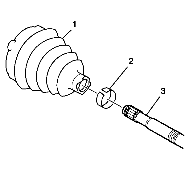
- Slide the boot (1) onto the wheel drive shaft (3).
- Install a new small boot clamp (2) onto the wheel drive shaft (3).
- Using a brass drift and a hammer, install the inner joint assembly onto the wheel drive shaft.

- Using snap ring pliers, install the new wheel drive shaft retaining ring (1).
- Ensure that the retaining ring (1) is properly seated in the groove on the wheel drive shaft.
- Install the boot into the inner joint.
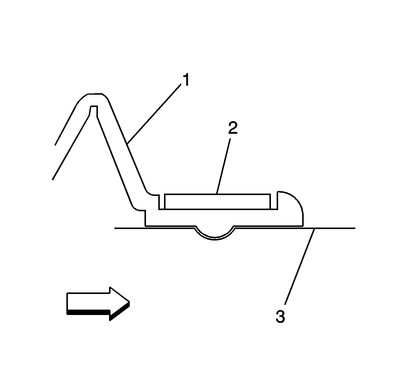
Important: The boot and clamp must be seated in the groove on the wheel drive shaft to ensure that the boot seals properly.
- Position the boot (1) and the clamp (2) on the wheel drive shaft (3) as shown.
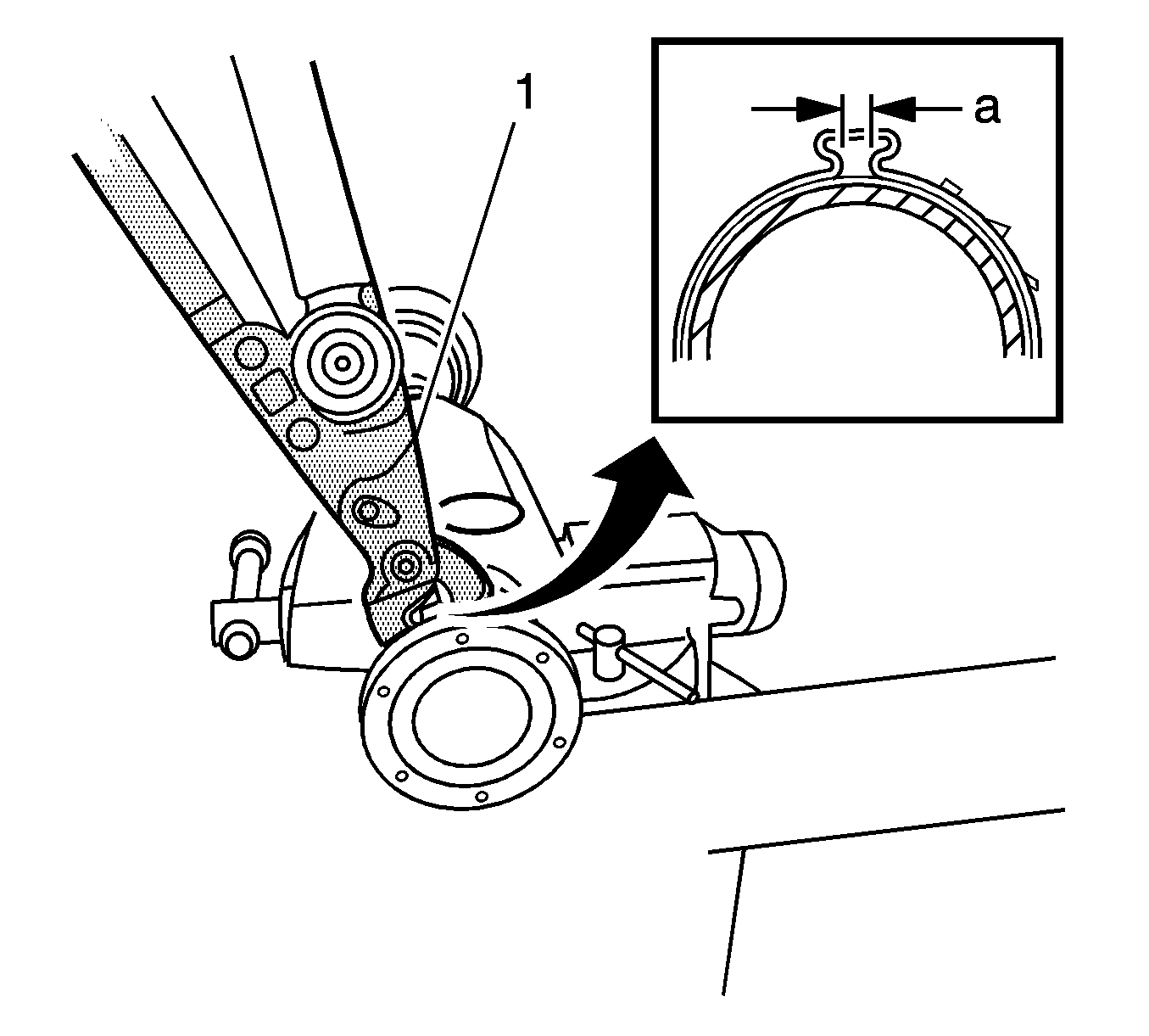
Important: The boot retaining clamp must not be over-tightened or under tightened.
- Using the
J 42572
(1), crimp the small boot clamp.
Tighten
Tighten the small boot clamp until the base of the clamp has a gap of 1 mm (0.039 in).
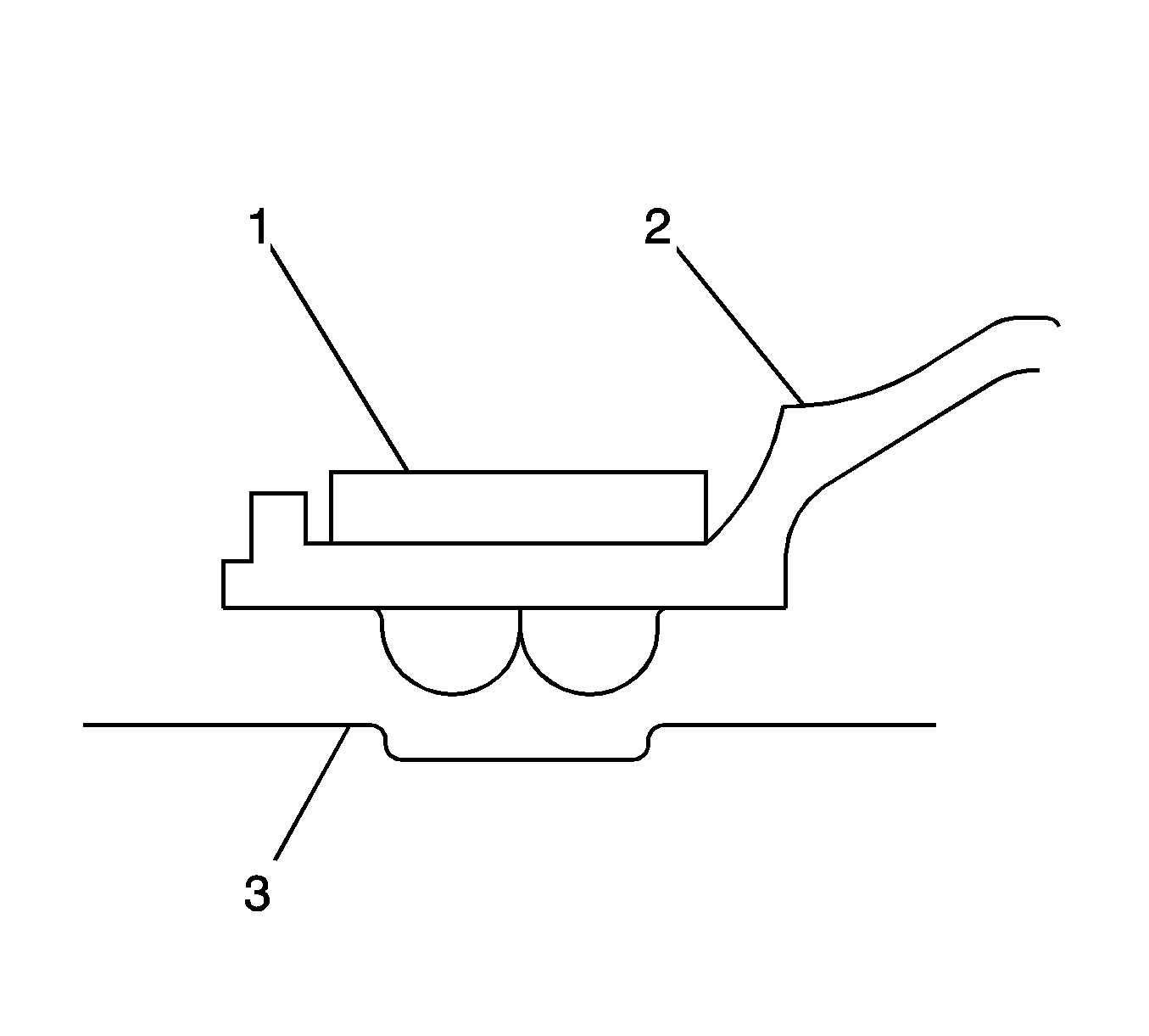
- Position the boot and the large clamp (1) and the boot (2) in the groove (3) in the joint.
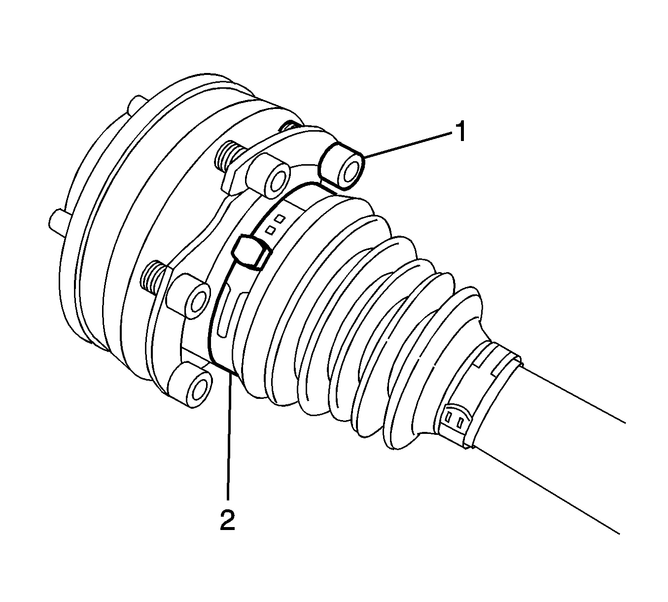
- Before crimping the clamp (2), position the clamp between the bolts and washers (1), as shown, to allow for the bolt installation and removal.
- Inspect the boot for the proper shape. If the boot is not shaped correctly, equalize the pressure in the boot by lifting the boot edge slightly and reshape the boot properly by hand.
- Inspect the boot for damage. If the boot was damaged during assembly, replace the boot.

Important: The boot retaining clamp must not be over-tightened or under tightened.
- Using the
J 42572
(1), crimp the large boot clamp.
Tighten
Tighten the large boot clamp until the base of the clamp has a gap of 1 mm (0.039 in).
- Using an alcohol based solvent, remove any grease or sealant from the cap for the inner joint and allow to air dry.
- Place a 3 mm (0.118 in) bead of sealant, GM P/N 88861422 (Canadian P/N 88861422) or equivalent, on the inside diameter of the joint face assembly.
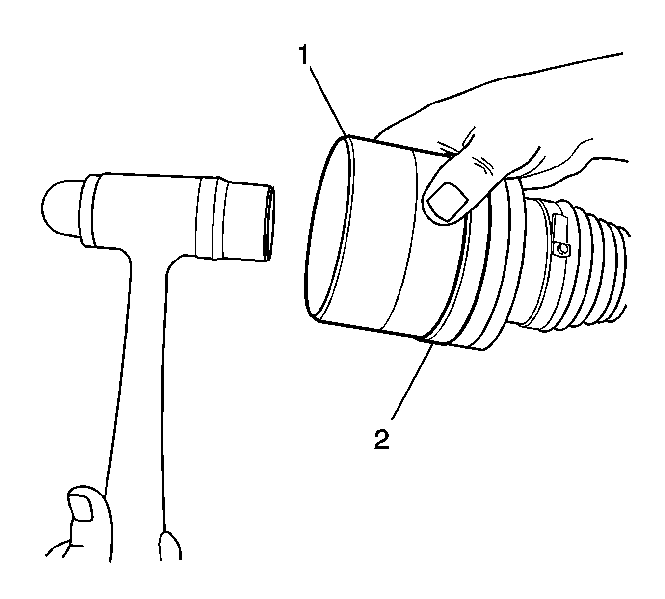
Important: Align the bolt holes in the grease cap with the bolt holes in the joint assembly.
- Using the
J-22928-B
(1), install the grease cap cover (2) to the joint assembly
- Inspect the inner joint for smooth operation. This will also distribute the grease within the joint.
| • | Hold the wheel drive shaft vertically, with the inner joint at the bottom. |
| • | Rotate the wheel drive shaft 4 or 5 times in a circular motion. |
- Install the wheel drive shaft. Refer to
Rear Wheel Drive Shaft Replacement.


