Tools Required
| • | J 45548
Mainshaft Support Bushing/Bearing Remover |
Case
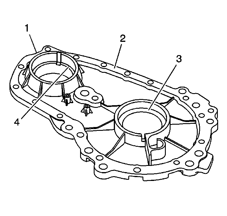
- Clean the front case half in cleaning solvent and air dry.
Notice: Refer to Machined Surface Damage Notice in the Preface section.
- Remove the sealer from the case sealing surfaces (2).
- Inspect the case for being broken or cracked.
- Inspect the front output shaft front bearing bore (4) for the following conditions:
- Inspect the input shaft bearing bore (3) for the following conditions:
- Replace the front case half if any of the above conditions are found.
- Inspect the sealing surfaces (2) for damage.
- Repair small scratches or nicks with a soft stone.
- Inspect the front case to transmission case mounting surface for damage.
- Inspect the front output shaft front bearing and the input shaft bearing for the following conditions:
- Replace the bearings if any of the above conditions are found. Refer to
Transfer Case Disassemble
and
Transfer Case Assemble
.
Cover
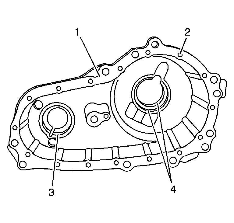
- Clean the cover in cleaning solvent and air dry.
Notice: Refer to Machined Surface Damage Notice in the Preface section.
- Remove the sealer from the case sealing surfaces.
- Inspect the case for being broken or cracked.
- Replace the case if it is broken or cracked.
- Inspect the sealing surfaces (1) for damage.
- Repair small scratches or nicks with a soft stone.
- Inspect the case threaded bolt holes (2) for damage.
- Repair any damaged threads.
- Inspect the front output shaft rear bearing bore (3) for the following conditions:
- Inspect the rear output shaft rear bearing bore (4) for the following conditions:
- Replace the case if the bearing has spun. Refer to
Transfer Case Disassemble
and
Transfer Case Assemble
.
Differential Components
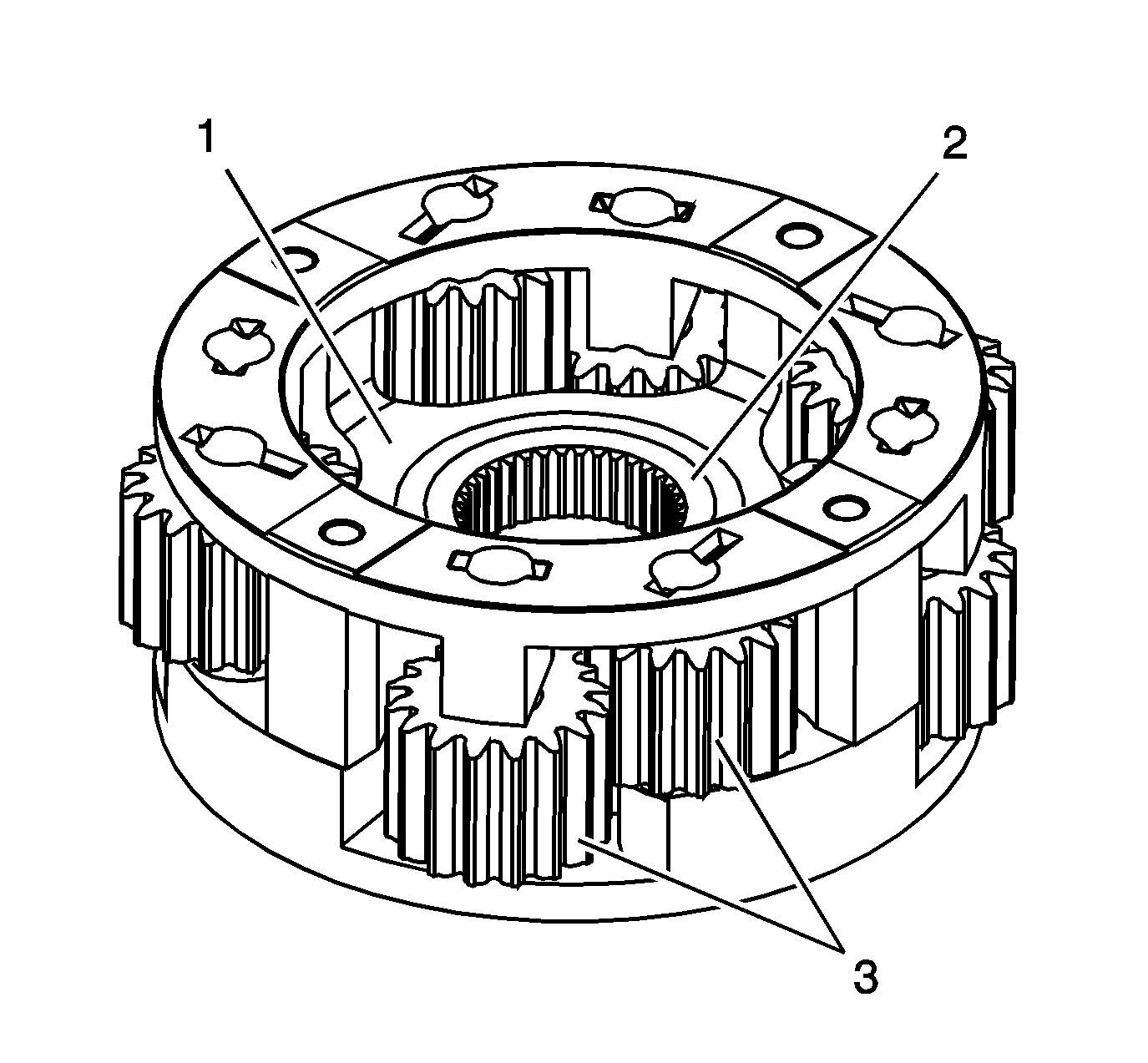
- Clean the planetary differential in cleaning solvent. Do not disassemble
the planetary differential.
- Air dry and ensure all cleaning solvent is removed from the bearings in the pinion gears (3). Do not spin the pinion gears with compressed air.
- Inspect the pinion gears for the following conditions:
| • | Debris embedded in the root of the teeth |
| • | Excessive side movement from worn bushings or shafts |
- Inspect the planetary housing for cracks at the web (1) of the housing.
- Inspect the thrust washer surface (2) for scoring or excessive wear.
- Inspect the planetary housing for distortion.
- Inspect the planetary housing to mainshaft splines for excessive wear.
- Replace the planetary differential if any of the above conditions are found.
- Inspect the planetary thrust washers for excessive wear or scoring.
- Replace the thrust washers if they are faulty.
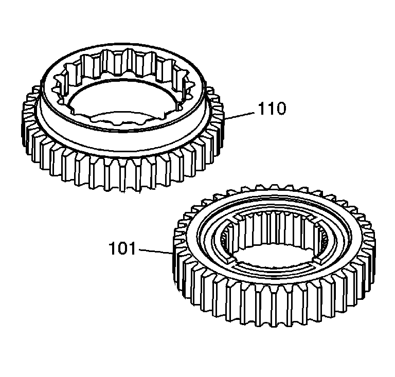
- Clean the front sun gear (110) and the rear sun gear (101) in cleaning solvent and air dry.
- Inspect the teeth on the front sun gear (110) and the rear sun gear (101) for the following conditions:
| • | Excessively worn gear surfaces |
| • | Slight wear marks are normal. |
| • | Debris embedded in the root of the teeth |
- Inspect the thrust washer surfaces for excessive wear or scoring.
- Replace the front sun gear (110) and the rear sun gear (101) if they are faulty.
Drive Chain and Sprockets
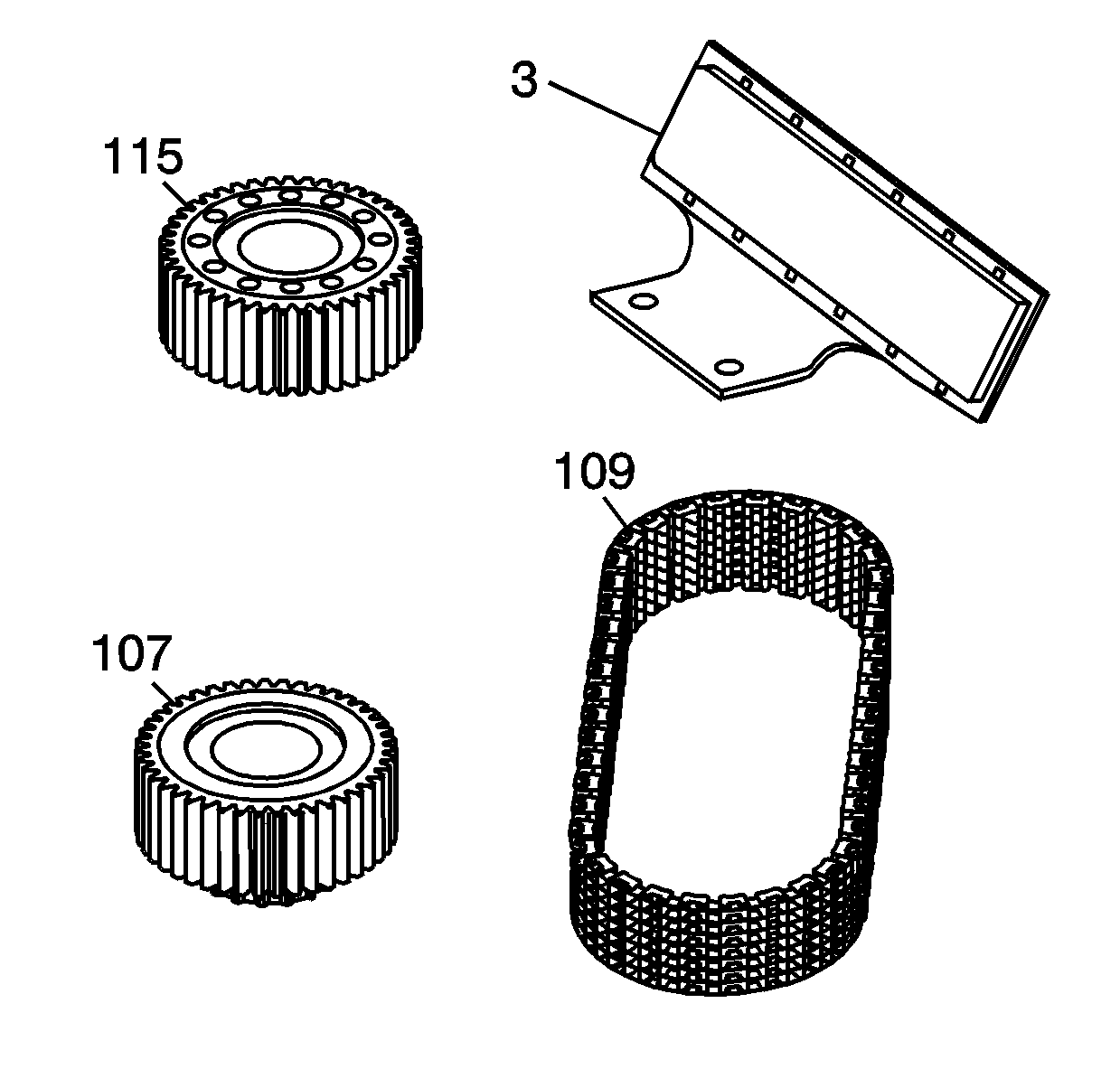
- Clean the drive chain (109), drive sprocket (107), snubber (3), and driven sprocket (115) in cleaning
solvent and air dry.
- Inspect the drive chain (109) for the following conditions:
| • | Debris embedded in the links |
- Replace the chain if any of the above conditions are found.
- Inspect the driven sprocket (115) and the drive sprocket (107) for the following conditions:
| • | Excessively worn gear surfaces |
| • | Slight wear marks are normal. |
| • | Debris embedded in the root of the teeth |
- Inspect the drive sprocket (107) and bushing (105) for the following conditions:
- Replace the sprockets if any of the above conditions are found. The chain and sprockets may be replaced separately.
- Inspect the snubber (3) for an excessively worn or gouged lining.
Slight wear marks are normal.
- Inspect the chain and sprockets for the cause of the wear. Replace as required.
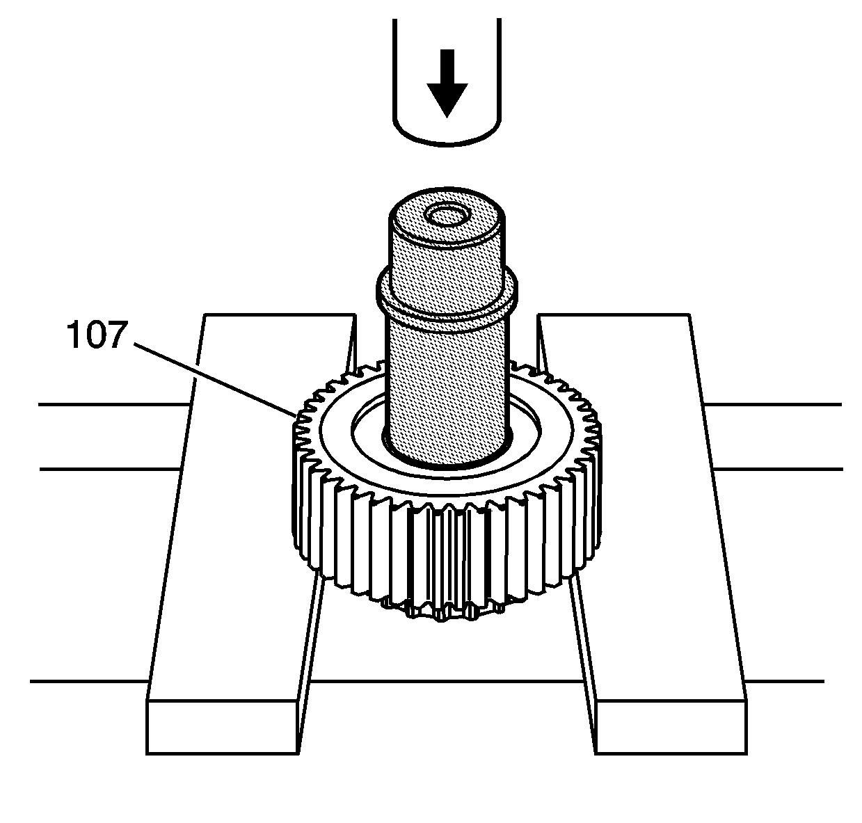
- If the bushing in the sprocket (107) is damaged, it can be replaced using the
J 46266
and a press to remove the bushing.
- Clean the bushing bore with solvent.
- Inspect the bushing bore for nicks or burrs.
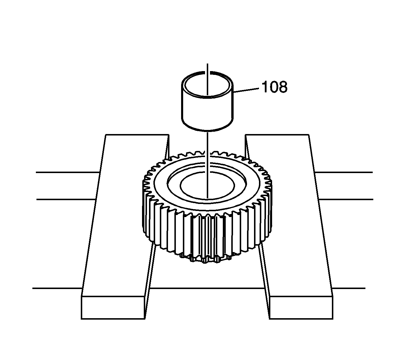
- Place the NEW bushing (108) in the sprocket bore.
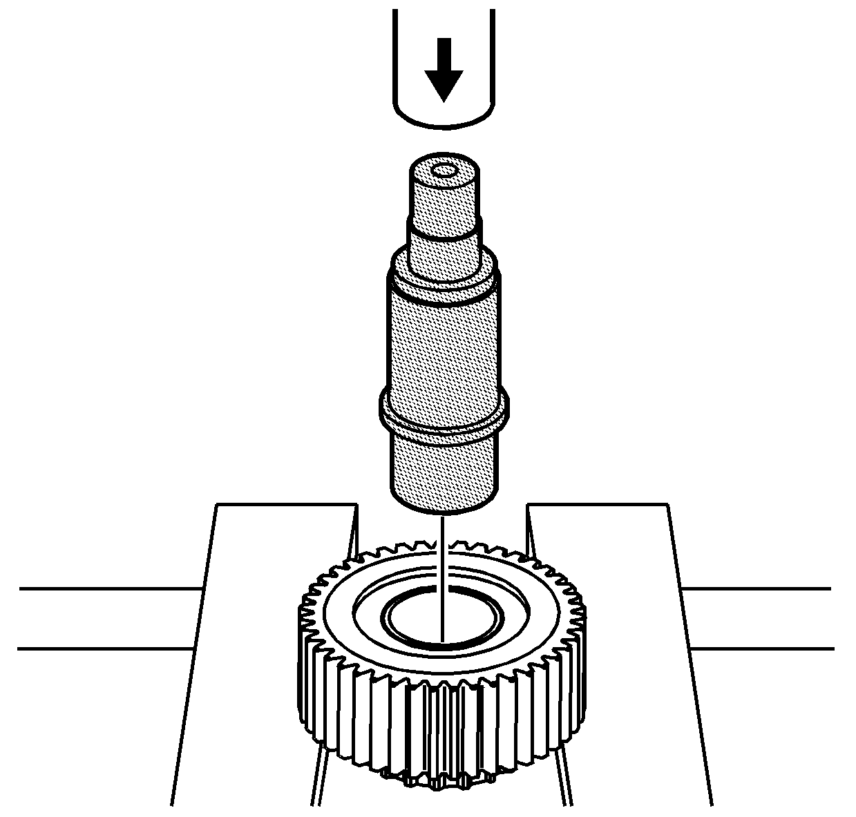
- Use the other side of the
J 46266
and press in the
NEW bushing until the tool meets the sprocket.
Input Shaft
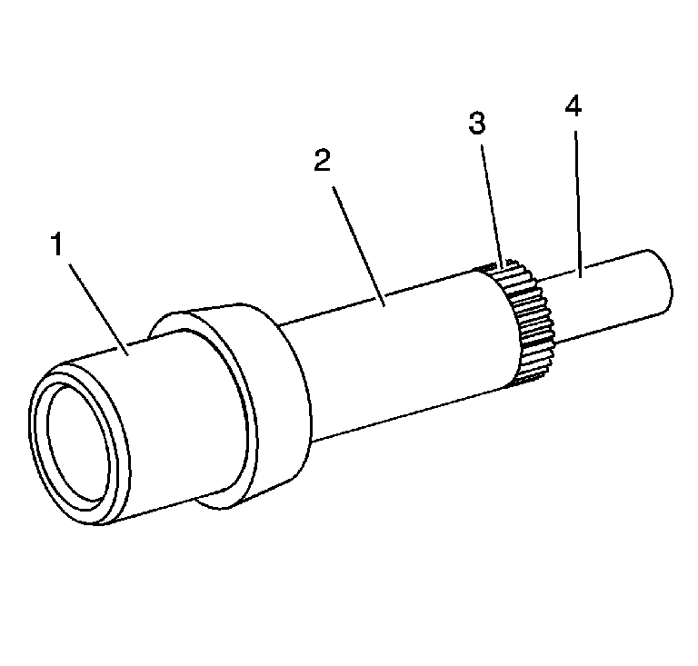
- Clean the input shaft in cleaning solvent.
- Inspect the input seal surface (1) for excessive grooves or damage.
Important: Do not attempt to smooth any roughness in the bearing journals.
- Inspect the bearing journals on the input shaft for the following conditions:
| • | The drive gear bushing (2) |
| • | The rear support bushing end (4) |
- Inspect the input shaft planetary carrier assembly splines (3) for damage or excessive wear. Witness marks at the location of the gear is normal.
- Replace the input shaft if any of the above conditions are found.
Front Output Shaft
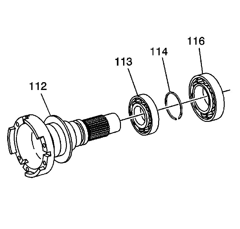
- Clean the front output shaft (112) in cleaning solvent and air dry.
- Inspect for spun bearings at the front output shaft bearing areas.
- Inspect the front output internal splines and driven gear splines for damage or excessive wear.
- Replace the front output shaft if it is damaged.
- Inspect the front output shaft bearings (113 and 116) for the following conditions:
- Replace the front output shaft bearings if they are faulty. Refer to
Transfer Case Disassemble
and
Transfer Case Assemble
.
Rear Output Shaft
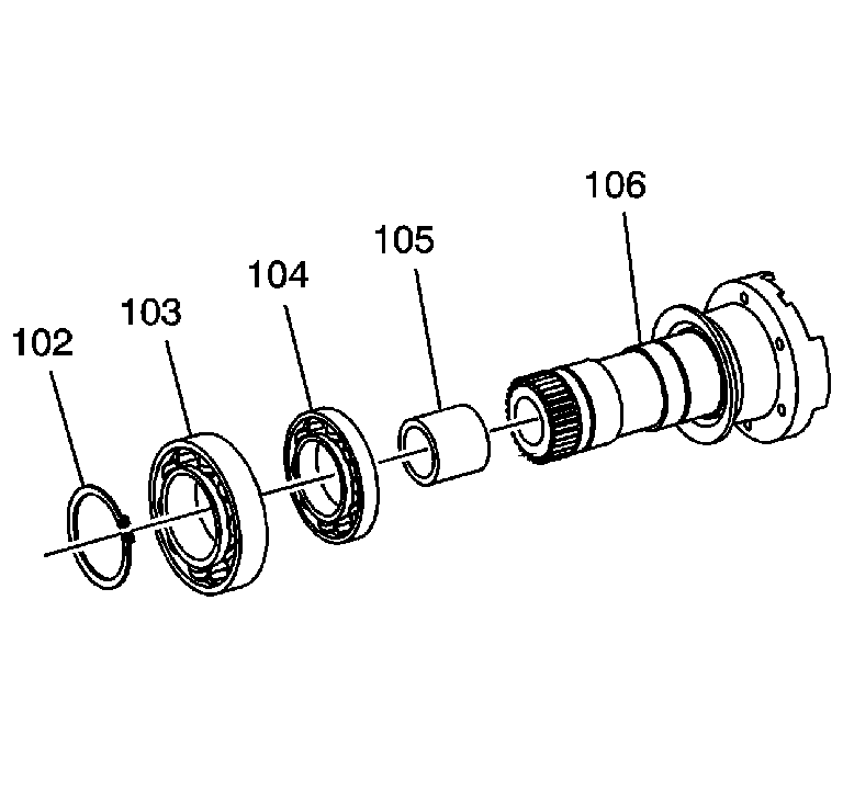
- Clean the rear output shaft (106) and rear output shaft bearings (104)
in cleaning solvent.
- Air dry and ensure all solvent is removed from the bearing.
- Inspect the rear output shaft bearings (103 and 104) for the following conditions:
- Replace the rear output shaft bearings if they are faulty. Refer to
Transfer Case Disassemble
and
Transfer Case Assemble
.
- Inspect the mainshaft rear support bushing (105) for the following conditions:
- Replace the rear output shaft if any of the above conditions are found.
- Inspect the rear output shaft splines for wear or damage.
- Inspect the rear output shaft bearing area for a spun bearing.
- If the bearing area or splines are damaged, replace the rear output shaft.
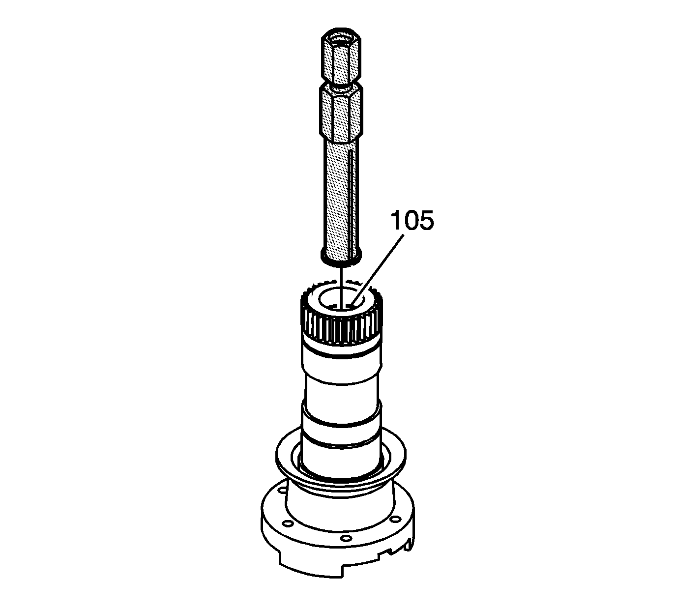
- If the bushing (105) is damaged, it can be replaced. Place the
J 45548
inside the bushing.
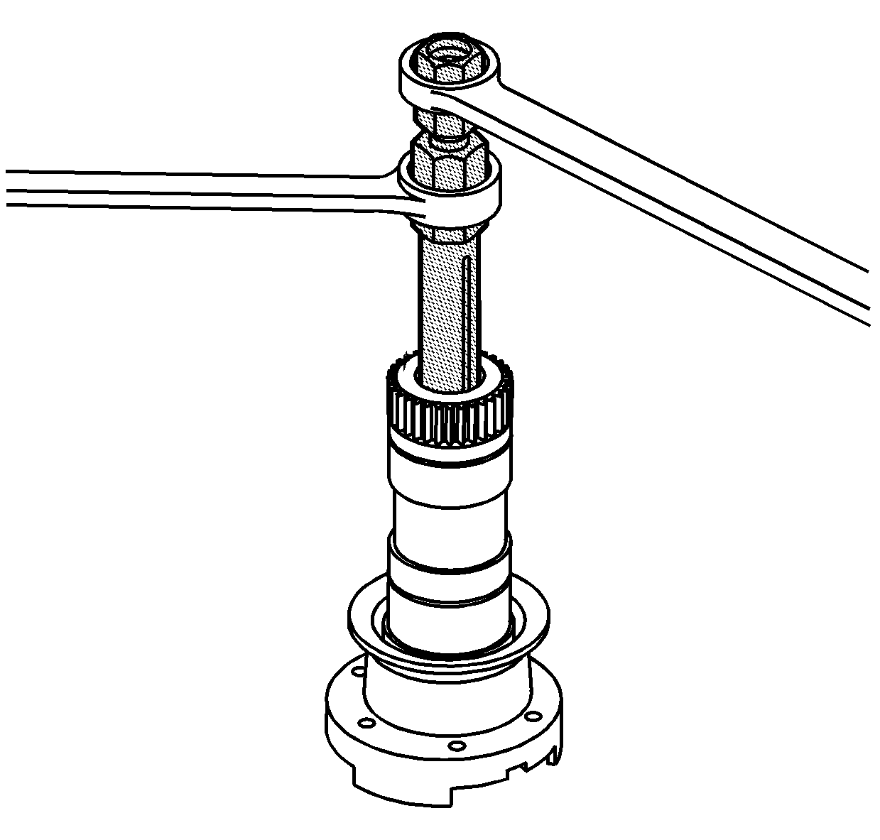
- With the ridge on the
J 45548
, behind the bushing, tighten the center bolt
of the
J 45548
in order to lock it behind the bushing.
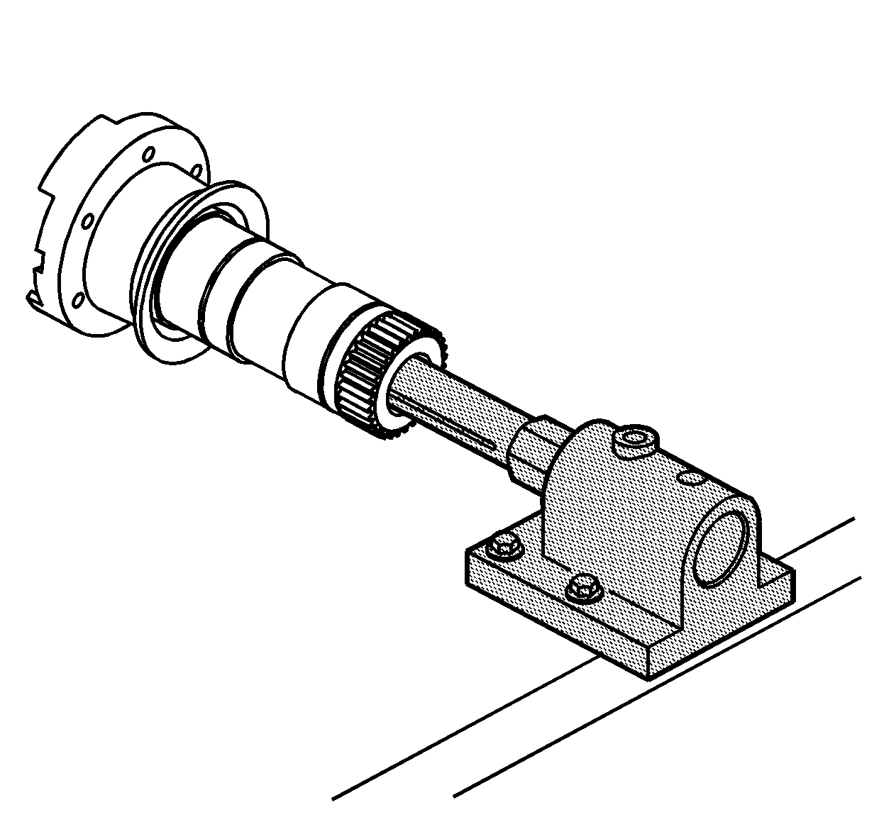
Important: Do not put the output shaft in a vise.
- With position pins removed from the
J 3289-20
, place the output shaft as shown.
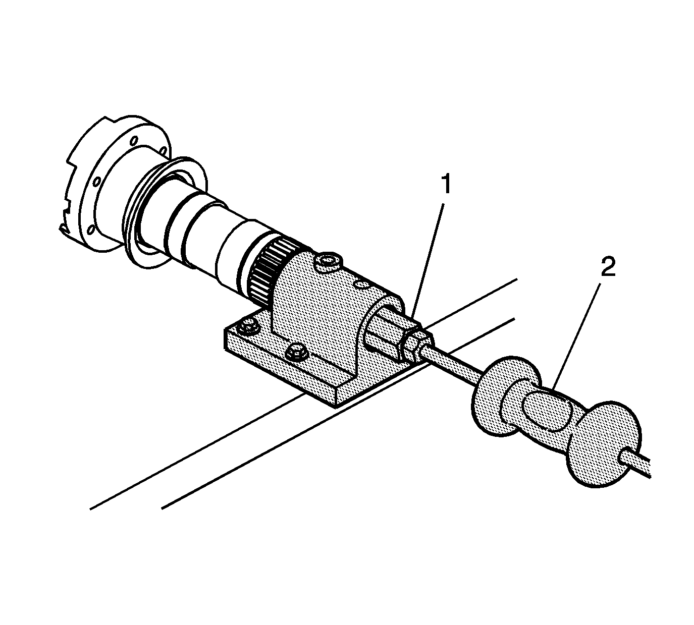
- Insert the
J-2619-A
(2) into the
J 45548
(1) and pull the bushing from the output shaft.
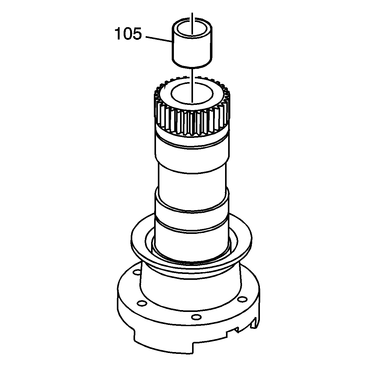
- Clean the bushing bore with solvent. Inspect for nicks and burrs.
- Place a NEW bushing (105) in the bore.
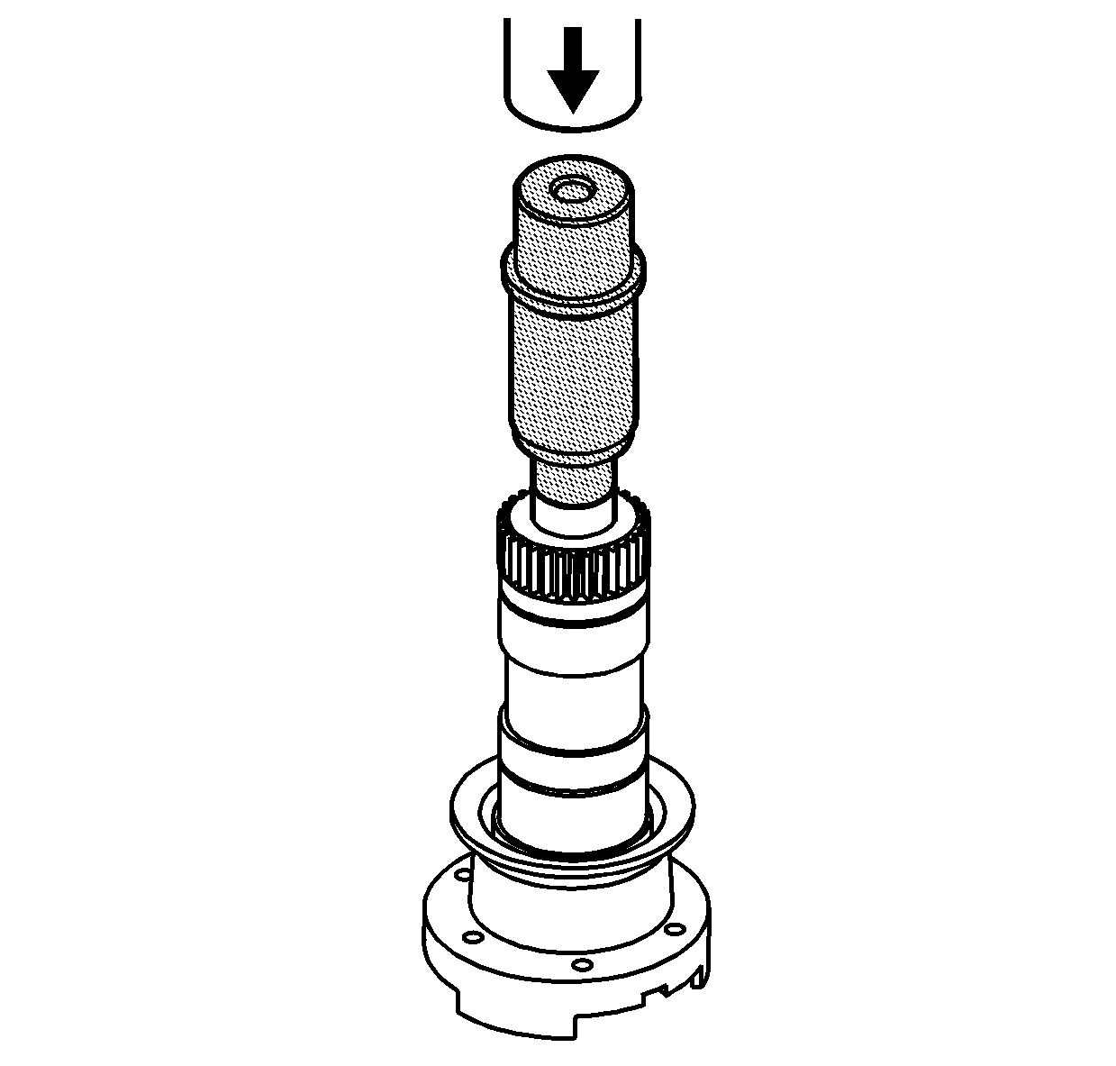
- Place the
J 46266
into the bushing as shown.
- Using a press, push the bushing into the bore until the tool meets the output shaft.


