1
| Head Restraint Guide
Procedure
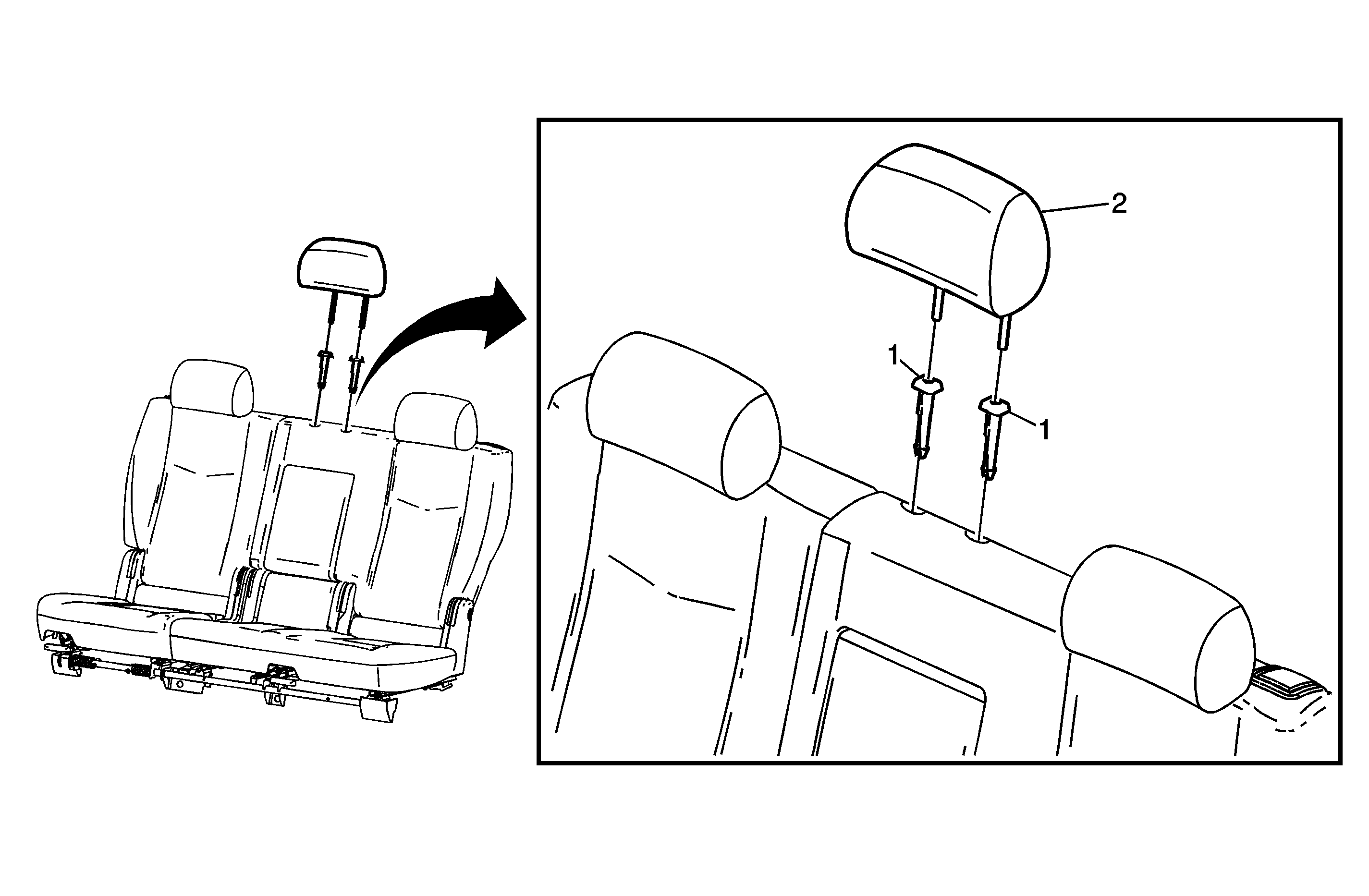
- Locate the 2 holes on the top of the seat back foam.
- Using a sharp cutting tool, cut a 20 mm (¾ in) wide X in the center of the depressions. The center of the X must be exactly 45 mm (1 ¾ in) from the center of the front seam.
- Fully install the left side guide pin. The small indicator hole on the pin should be facing inboard.
- Fully install the right side guide pin. The button should be facing outboard.
|

